Getting Started with SysConfig#
The objective of this lab is to help you gain familiarity with using SysConfig. SysConfig (system configuration) is a graphical user interface (GUI) tool created to help simplify project development in TI’s Code Composer Studio (CCS) working environment. SysConfig can be used for PinMux configuration, peripheral setup, and the generation of C-code using C2000Ware DriverLib application programming interface (API). When using this tool, corresponding C-code is automatically generated and included in the project as you edit the SysConfig GUI settings.
This lab exercise demonstrates how to use the SysConfig GUI tool to toggle LEDs on your C2000 device.
Solution#
All C2000 Academy lab software solutions are located in the directory: [C2000Ware_Install_Path]/training/device/[device_name].
Lab Setup#
For more details on initial setup and navigating CCS, please refer to the Getting Started with CCS Lab.
Hardware Setup#
This lab exercise is intended for LaunchPad and controlCARD C2000 devices. Using the supplied USB cable, connect the USB Micro or Mini Type-B connector into your C2000 board and the USB Standard Type-A connector into your computer’s USB port (please note that controlCARD docking stations may require an additional power supply connection). This connection will power the board and provide a JTAG communication link between your device and CCS.
Software Setup#
The following software and tools are required to run these labs on C2000 microcontrollers:
TI’s Code Composer Studio (CCS) : Integrated Development Environment for development of code for C2000 family of devices
C2000Ware software development kit (SDK) : Low level drivers, highly optimized libraries, examples to get started with C2000 family of devices.
Import an Empty Project#
Import empty SysConfig project from C2000Ware DriverLib examples. Go to CCS menu File → Import…
Click ‘Browse…’ button
Go to
[C2000ware Install_dir]/training/device/[device]/empty_lab.The default install folder in Windows is
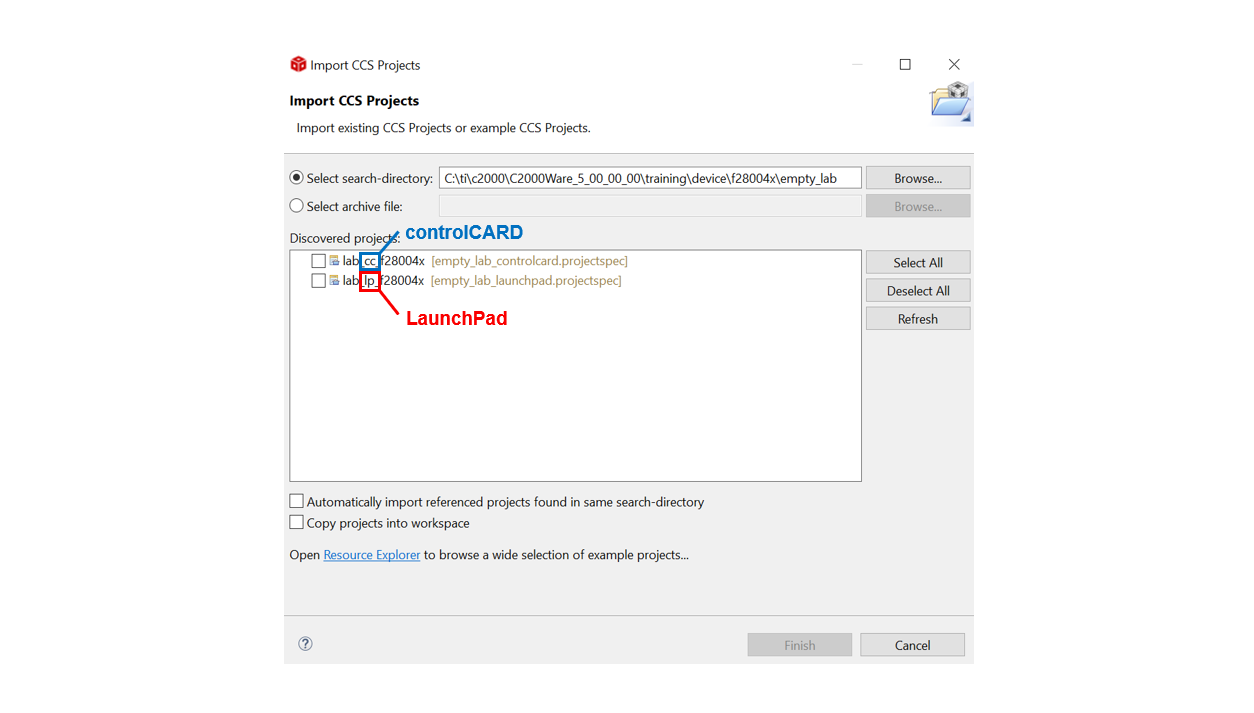
C:/ti/C2000Ware_X_XX_00_00. For current device name, check your board LaunchXL, or controlCARD.Select the project corresponding to the device being used from the list of ‘Discovered Projects’. The recommended project for each device is listed below
Select:
lab_cc_[device]if you have a controlCARDlab_lp_[device]if you have a Launchpad
Configure the LED GPIOs#
Use SysConfig User-Interface to configure the GPIO lines for LEDs. This exercise uses two LEDs on LaunchPad orcontrolCARD board.
Open the empty SysConfig file by double-clicking
lab_;[lab name]_[device].syscfgfile in project explorer window.

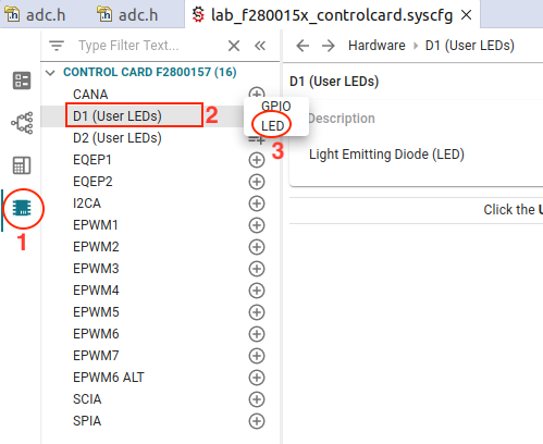
Step 1 : Click on the
Hardwaretab on the left sideStep 2 : Select both of the “User LEDs” (D1/D2 on controlCARD, LED4/LED5 on Launchpad)
Step 3 : Add both as
LEDtype
Once both LEDs are added, open the lab_main.c file and add copy in the initialization code below. The
Device_init()must be called to initialize the platform.
#include "driverlib.h"
#include "device.h"
#include "board.h"
//
// Main
//
void main(void)
{
   // Device Initialization
   Device_init();
   //
   // Initializes Peripheral Interrupt Expansion module (PIE) and clears PIE registers. Disables CPU interrupts.
   //
   Interrupt_initModule();
   //
   // Initializes the PIE vector table with pointers to the shell Interrupt
   // Service Routines (ISR).
   //
   Interrupt_initVectorTable();
   Board_init();
   //
   // Enable Global Interrupt (INTM) and realtime interrupt (DBGM)
   //
   EINT;
   ERTM;
   while(1)
   {
   }
}
Configure the CPU Timer#
Open the sysconfig GUI again (‘Software’ tab)
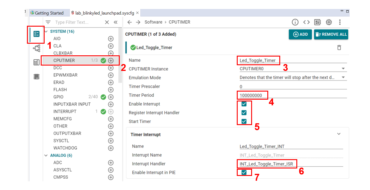
Step 1: Open the
Softwaretab on the left-sideStep 2: Add a CPU timer by pressing the ‘+’ next to
CPUTIMERStep 3: Add the timer name as : Led_Toggle_Timer
Step 4: Set the Timer Period as 100000000
Step 5: Check the boxes next to
Enable interrupt,Register Interrupt Handler, andStart TimerStep 6: Add an Interrupt Service Routine (ISR) and check the default interrupt handler name matches
INT_Led_Toggle_Timer_ISRas seen belowStep 7: Check the box next to
Enable Interrupt in PIE
Add timer handler code to your the main.c source file below your ‘Main’. Make sure that the interrupt handler function name is same as provided in the sysconfig parameter in picture above.
__interrupt void INT_Led_Toggle_Timer_ISR(void)
{
    GPIO_togglePin(myBoardLED0_GPIO);
    GPIO_togglePin(myBoardLED1_GPIO);
    Interrupt_clearACKGroup(INT_Led_Toggle_Timer_INTERRUPT_ACK_GROUP);
}
Build and Run the Project#
Ensure that the USB cable from your LaunchPad or controlCARD is connected to your computer.
Under the Build button, be sure the CPU1_RAM build configuration is highlighted. Use the ‘Build’ button to build your program. Fix any compilation errors.
Now we will start the debug session by clicking the ‘Debug’ button. You should now see the debugging session open up and the debugger should pause when it has reached
main().Click the green Resume button to run the program.
Look at your board, you should see an LED toggling on and off.
Terminate the Debug Session and Close Project#
The ‘Terminate’ button will terminate the active debug session, close the debugger, and return Code Composer Studio (CCS) to the ‘CCS Edit’ perspective view again. Click: Run → Terminate or use the red, square terminate icon.
Next, close the project by right-clicking on project in the ‘Project Explorer’ panel and select
Close Project.
Full Solution#
The full solution to this lab exercise is included as part of the C2000Ware
SDK. You can import this solution project from the directory:
<c2000ware_install_path>/training/device/<device_name>/getting_started/lab_binkyled_sysconfig.
Feedback
Please provide any feedback you may have about the content within this Academy to: c2000_academy_feedback@list.ti.com