Use MCUBoot to Upgrade a TrustZone Enabled Image#
Introduction#
ARM TrustZone allows for hardware-enforced isolation by defining memory partitions. In this lab we will look at how we can use MCUBoot to upgrade an application that is TrustZone enabled by using the Dual Slot feature of MCUBoot.
Task 0: Program the secure image and a non-secure application image using Uniflash.
Task 1: Program MCUBoot, the secure image, and two versions of the non-secure image.
Prerequisites#
Hardware#
You will need one LaunchPad and one debugger to run this SimpleLink Academy lab.
Devices with TrustZone functionality are:
Debugger boards:
Software#
Code Composer Studio. Make sure your version of CCS is supported by the SimpleLink SDK you are using. You can find supported CCS versions in the SimpleLink™ cc13xx_cc26xx SDK Release Notes.
Further reading#
If you want to know more about MCUBoot, check out the online MCUBoot documentation.
If you want to learn more about TrustZone and the secure image, the User’s Guides have a chapter called “Security Features of CC13x4 and CC26x4 Devices”. You can also see the ARM Cortex-M33 documentation.
For any questions you may have, please consult the relevant E2E forum, TI Sub-1 GHz E2E Forum.
Secure and Non-Secure Memory#
Primary and Secondary Image Slots#
The bootloader distinguishes between Primary and Secondary image slots.
Primary image slots contain the currently running image(s). Primary image slots must be located on-chip (internal flash).
Secondary image slots are used for storing incoming OAD image(s). When MCUBoot wakes up, it determines whether any image in the secondary slots should be copied to a primary slot. Secondary image slots can be located on chip (internal flash) or off-chip (external flash).
When using MCUBoot in combination with a TrustZone enabled example, we want to keep the secure image in a dedicated image slot. This means that we need two Primary image slots:
Primary slot 1 contains the secure image
Primary slot 2 contains the non-secure image, i.e. the application image. In this case the tfm_empty image.
In MCUBoot, the situation where we have two primary slots is called DUAL_SLOT.
In DUAL_SLOT mode, we will also have two secondary slots:
Secondary slot 1 can be used to upgrade the Primary slot 1. Thus it would only make sense to use this slot if we need to upgrade the secure image.
Secondary slot 2 can be used to upgrade the Primary slot 2. We will use this slot for upgrading the non-secure image, i.e. the application image.
Flash Memory Map#
In MCUBoot, the flash memory map is determined by the flash_map_backend.h file.
In this file we can define the address and size of each of the image slots
(Primary 1, Primary 2, Secondary 1, Secondary 2).
For CC13x4 and CC2674 devices, the following suggestion is given for the
DUAL_SLOT, internal flash use case:
        #define BOOTLOADER_BASE_ADDRESS         0x00000800
        #define BOOT_BOOTLOADER_SIZE            0x00006000

        #define BOOT_PRIMARY_1_BASE_ADDRESS     0x0000d000
        #define BOOT_PRIMARY_1_SIZE             0x0002b000

        #define BOOT_PRIMARY_2_BASE_ADDRESS     0x00038000
        #define BOOT_PRIMARY_2_SIZE             0x0004e800

        #define BOOT_SECONDARY_1_BASE_ADDRESS   0x00086800
        #define BOOT_SECONDARY_1_SIZE           0x0002b000

        #define BOOT_SECONDARY_2_BASE_ADDRESS   0x000b1800
        #define BOOT_SECONDARY_2_SIZE           0x0004e800
The bootloader and Primary slot sizes are determined based on the code size of MCUBoot and the secure image. The Secondary slot size is just the remaining memory.
MCUBoot Image Upgrade Decisions#
In the MCUBoot example readme, a table is given with all the permutations of
images stored in each slot, and what the corresponding MCUBoot image upgrade
decision is. Since we are using DUAL_SLOT mode we have to look at the
corresponding table. An excerpt is included below, but you can find the full
table and documentation in the MCUBoot example readme.
We will aim to get to situation 133: Primary slot 1 is programmed with image A (secure image), Primary slot 2 is programmed with image C (tfm_empty 1.0.0), Secondary slot 1 is empty, secondary slot 2 is programmed with image D (the newer tfm_empty image 1.0.1).
# |
Slot 0 (Prim) before |
Slot 1 (Prim) before |
Slot 2 (Sec) before |
Slot 3 (Sec) before |
Boot status |
Slot 0 (Prim) after |
Slot 1 (Prim) after |
Slot 2 (Sec) after |
Slot 3 (Sec) after |
|---|---|---|---|---|---|---|---|---|---|
133 |
A |
C |
Empty |
D |
[0, 2] [1, 3] UP BOOT |
A |
D |
Empty |
Empty |
From the Boot status column we can see that slot index 0 (Primary slot 1) will
be compared with index 2 (Secondary slot 1). Slot index 1 (Primary 2) will be
compared to index 4 (Secondary 2). UP refers to the fact that an image slot
will be updated. BOOT indicates that the primary image will successfully be booted.
When MCUBoot has finished running, we will be left with image A (secure image) in Primary slot 1 and image D (newer tfm_empty image 1.0.1) in Primary slot 2.
Hint
In MCUBOOT_OVERWRITE_ONLY mode, MCUBoot will only move an image from a Secondary
slot to a Primary slot if it has a higher version number than the image
currently residing in the Primary image slot.
It’s also worth noting that Primary slot 1 can only be upgraded with an image from Secondary slot 1, and Primary slot 2 can only be upgraded with an image from Secondary slot 2.
Task 0: Run the TrustZone Enabled example on your LaunchPad#
If you already have the TrustZone enabled example (tfm_empty) running on your device, you can skip this task.
In this step we will run the TrustZone enabled example on our device (without MCUBoot). This example has two components:
Secure image (tfm_s)
Application image (tfm_empty)
You can find instructions for debugging the project in CCS in the tfm_empty example readme. However we will rather just program the device with Uniflash.
Start by importing the application to CCS. The following instruction covers the ´tfm_empty´ example, but you can apply them to any ´tfm_´ example. You can choose any RTOS and compiler version.
Add the following post-build step to the tfm_aescbc example (Properties -> Build -> Post-build steps). This will generate a hex file when the project is built.
${CG_TOOL_HEX} -order MS --memwidth=8 --romwidth=8 --intel -o ${ProjName}.hex ${ProjName}
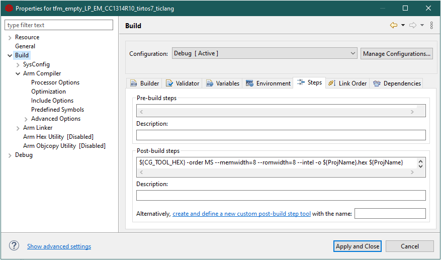
Properties -> Build -> Post-build steps#
Build the project and verify that the Debug folder contains a hex file.
Open Uniflash and connect to your LaunchPad. It’s always a good idea to erase the flash of the device before we start. You can open Settings and Utilities and press the Erase Entire Flash button.
We now have to restart the Uniflash session and reconnect with the LaunchPad.
Browse to your CCS workspace and add the hex file (e.g.
workspace\tfm_empty_LP_EM_CC1314R10_tirtos7_ticlang\Debug\tfm_empty_LP_EM_CC1314R10_tirtos7_ticlang.hex).Add the secure image,
<SDK_INSTALL_DIR>/tfm_s/build/cc26x4/production_full/Release/outputs/CC26X4/tfm_s.hex
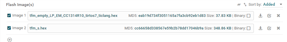
Program the hex files.#
Press the Load Images button. When uniflash is finished, press the reset button on the device. If the example runs correctly the red LED will blink with 1 s interval.
Task 1: Adding MCUBoot to the Mix#
If we want to use over the air download (OAD) to upgrade the firmware on our device, we need to add a bootloader to keep track of the different images. For CC13x4 and CC2674 devices, we use the open source MCUBoot bootloader.
You can read more about OAD in the User’s Guide for each stack (Bluetooth Low Energy, TI Wi-SUN FAN Stack, Proprietary RF etc). All of the User’s Guides are linked on the Documentation Overview.
You can read more about MCUBoot in the online MCUBoot documentation.
In this task we will adapt the memory map outlined in the Secure and Non-Secure Memory section. We will use internal flash for storing the secondary image slots. Thus we will end up with the following memory map:
Slot |
1 |
Address |
2 |
Address |
|---|---|---|---|---|
Bootloader |
MCUBoot |
0x00800 |
- |
- |
Primary |
Secure image (tfm_s) |
0x0D000 |
tfm_empty 1.0.0 |
0x38000 |
Secondary |
None |
0x86800 |
tfm_empty 1.0.1 |
0xB1800 |
Prepare MCUBoot#
Import the mcuboot example to CCS
Since we are planning to use TrustZone, right-click the project, select Build Configuration -> Set Active and select TZ_Enabled
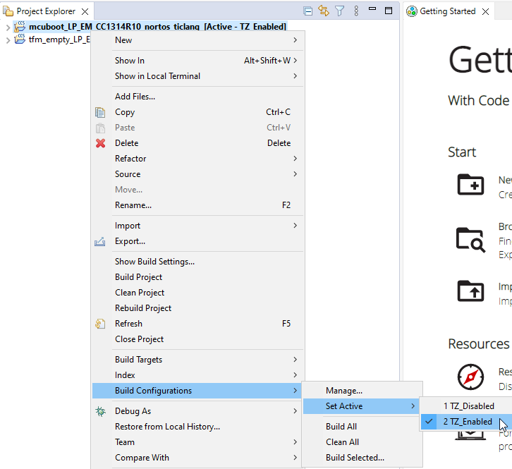
Set Build Configuration to TZ_Enabled#
Open Sysconfig -> Device Configuration and set the Address of Flash Vector Table to 0x00000800. This tells the program that the MCUBoot vector table starts at 0x800. (Usually the vector table starts at 0x00000000.)
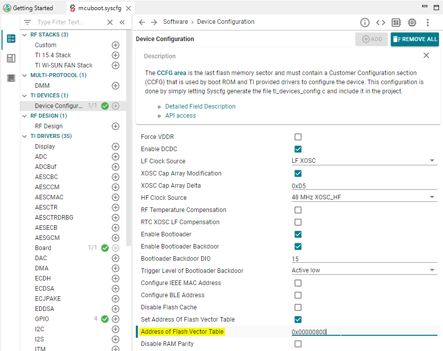
Set the Address of Flash Vector Table to 0x00000800#
Open mcuboot_config/mcuboot_config.h. This file lets us configure a bunch of settings for MCUBoot.
When only using internal flash, make sure the
TI_BOOT_USE_EXTERNAL_FLASHdefine is commented out.
/*
 * Support for off-chip memory (external flash)
 *
 * If the desired configuration is for MCUBoot to search for valid images
 * in external flash, TI_BOOT_USE_EXTERNAL_FLASH must be defined.
 *
 * Note that if external flash is used, then also uncomment
 * MCUBOOT_OVERWRITE_ONLY and comment out MCUBOOT_DIRECT_XIP.
 * MCUBOOT_DIRECT_XIP is not supported when external flash configuration
 * is enabled.
 *
 * */
/* Uncomment to enable external flash configuration */
//#define TI_BOOT_USE_EXTERNAL_FLASH
For dual image, only the
MCUBOOT_OVERWRITE_ONLYupgrade mode is supported. Thus we need to make sure the selected upgrade mode isMCUBOOT_OVERWRITE_ONLY. Check that this one is not commented, but all other upgrade modes are commented.
/*
 * Upgrade mode
 *
 * The default is to support A/B image swapping with rollback.  Other modes
 * with simpler code path, which only supports overwriting the existing image
 * with the update image or running the newest image directly from its flash
 * partition, are also available.
 *
 * You can enable only one mode at a time from the list below to override
 * the default upgrade mode.
 */

 /* Uncomment to enable the overwrite-only code path. */
#define MCUBOOT_OVERWRITE_ONLY

/* Uncomment to enable the direct-xip code path. */
//#define MCUBOOT_DIRECT_XIP

#if defined(TI_BOOT_USE_EXTERNAL_FLASH) &&  \
	(!defined(MCUBOOT_OVERWRITE_ONLY) || defined(MCUBOOT_DIRECT_XIP))
    	#error "If external flash is configured, only MCUBOOT_OVERWRITE_ONLY is supported"
#endif

/* Uncomment to enable the revert mechanism in direct-xip mode. */
/* #define MCUBOOT_DIRECT_XIP_REVERT */

/* Uncomment to enable the ram-load code path. */
/* #define MCUBOOT_RAM_LOAD */

/* Uncomment to use image version for rollback protection. */
//#define MCUBOOT_HW_ROLLBACK_PROT
Build the mcuboot example so we have the hex file ready.
Prepare the tfm_empty Project#
When running the tfm_empty project along the MCUBoot project we need to make a couple of changes:
MCUBoot verifies every image on the device. Thus we need to add an OAD Image Header to the images that we want to program on the device. This goes for both the secure image (tfm_s) and the non-secure image (tfm_empty).
MCUBoot also authenticates each image. Thus we need to sign the images.
The device only has one CCFG section. This section is controlled by MCUBoot. We will thus remove this part of the tfm_empty image.
We can make all these changes with the imgtool provided by MCUboot. You can find more information about imgtool in the MCUBoot imgtool documentation.
You can download python and use it to run imgtool. However here we will instead instruct CCS to run imgtool as a post-build step when building the tfm_empty project.
Open the Project -> Properties -> Build. We will add our post build step here.
The instruction will have the following format:
Run the tiarmobjcopy tool to transform the
.outfile to a.binfile, and remove the ccfg section.Run the imgtool to add an oad image header to the
.binfile. Add a signature with the example certificate. Set the image version to 1.0.0.Then repeat both steps for the secure image.
${CG_TOOL_ROOT}/bin/tiarmobjcopy -O binary ${ProjName}.out ${ProjName}-noheader.bin  --remove-section=.ccfg
${COM_TI_SIMPLELINK_CC13XX_CC26XX_SDK_INSTALL_DIR}/tools/common/mcuboot/imgtool sign --header-size 0x100 --align 4 --slot-size 0x4e800 --version 1.0.0 --pad-header --pad --key ${COM_TI_SIMPLELINK_CC13XX_CC26XX_SDK_INSTALL_DIR}/source/third_party/mcuboot/root-ec-p256.pem ${ProjName}-noheader.bin ${ProjName}.p2_ns.bin
${CG_TOOL_ROOT}/bin/tiarmobjcopy -O binary ${COM_TI_SIMPLELINK_CC13XX_CC26XX_SDK_INSTALL_DIR}/tfm_s/build/cc26x4/production_full/Release/outputs/CC26X4/tfm_s.axf ${PROJECT_ROOT}/tfm_s.bin  --remove-section=.ccfg
${COM_TI_SIMPLELINK_CC13XX_CC26XX_SDK_INSTALL_DIR}/tools/common/mcuboot/imgtool sign --header-size 0x100 --align 4 --slot-size 0x2b000 --version 1.0.0 --pad-header --pad --key ${COM_TI_SIMPLELINK_CC13XX_CC26XX_SDK_INSTALL_DIR}/source/third_party/mcuboot/root-ec-p256.pem ${PROJECT_ROOT}/tfm_s.bin tfm_s.mb.bin
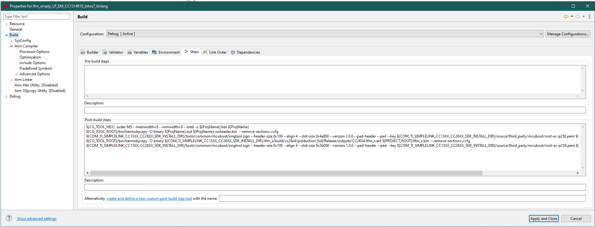
Project -> Properties -> Build#
After hitting “Apply and Close” and rebuilding the tfm_empty project, you should see the following
.binfiles in your output folder (Debug).
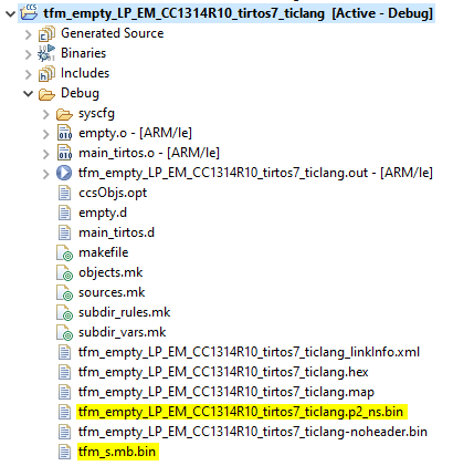
You should see the following .bin files in your output folder (Debug).#
Program the MCUBoot and Primary Slots#
We are now going to program our device. Let’s start by programming only MCUBoot and the two Primary slots to double-check that the images we have built so far work.
Connect your LaunchPad to your laptop with the LP_XDS110ET and open uniflash. Detect your launchpad and start the uniflash session.
Again, let’s erase the flash of the device before we start. You can open Settings and Utilities and press the Erase Entire Flash button. We now have to restart the Uniflash session and reconnect with the LaunchPad.
Let’s program MCUboot, primary slot 1 and primary slot 2 according to the memory map at the beginning of this task.
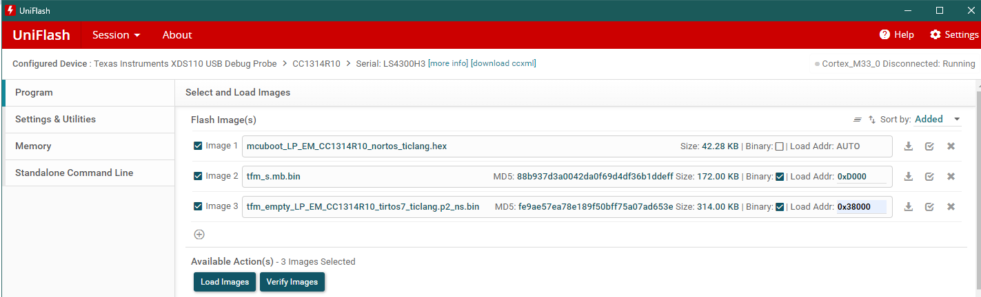
Program MCUboot, primary slot 1 and primary slot 2.#
After Uniflash has finished programming the device, press the reset button on the board. You should see the following happening:
When MCUBoot starts running, the red LED is lit. The green LED will blink three times to indicate boot was successful.
When MCUBoot has finished running it will boot into the secure image.
When the secure image has finished the initializing code, it will pass control to the tfm_empty application. At this point the red LED will start blinking with 1 s interval.
Prepare the New Application Image#
We will now compile a “new” application image, version 1.0.1. Let’s add a small code change so that we can determine which image is running on the device. You can make any change you want, here we’ll go through how to change the interval of the LED blink.
Open
empty.cfrom the tfm_empty project folder.Find the
timevariable in themainThreadand change it to 5. This will give us a 5 second blink interval.
    /* 5 second delay */
    uint32_t time = 5;
When we build the project, we will overwrite the version 1.0.0 bin file. If you want to keep it, copy it to a different folder than the Debug folder.
Now, let’s change our post-build step. Open the Project -> Properties -> Build. We need to increment the
--versionof our tfm_empty step (to 1.0.1):
${CG_TOOL_ROOT}/bin/tiarmobjcopy -O binary ${ProjName}.out ${ProjName}-noheader.bin  --remove-section=.ccfg
${COM_TI_SIMPLELINK_CC13XX_CC26XX_SDK_INSTALL_DIR}/tools/common/mcuboot/imgtool sign --header-size 0x100 --align 4 --slot-size 0x4e800 --version 1.0.1 --pad-header --pad --key ${COM_TI_SIMPLELINK_CC13XX_CC26XX_SDK_INSTALL_DIR}/source/third_party/mcuboot/root-ec-p256.pem ${ProjName}-noheader.bin ${ProjName}.p2_ns.bin
Build he project and verify that we now have a 1.0.1 image in the output folder (Debug folder).
Programming All the Images#
This time, there are four different images we have to keep track of:
MCUBoot (including CCFG)
Primary 1: Secure image
Primary 2: tfm_empty application 1.0.0
Secondary 2: tfm_empty application 1.0.1
When we restart the device, we want MCUBoot to find the tfm_application image 1.0.1 and move it from secondary 2 to primary 2. Then it should boot into the secure image, and then the tfm_empty image 1.0.1.
Since we already have MCUBoot, secure image and tfm_empty v.1.0.0 on the device, we will just add the tfm_empty image version 1.0.1.
In the flash_map_backend.h file, BOOT_SECONDARY_2_BASE_ADDRESS is given as
0x000b1800. We will instruct Uniflash to program the image to this address.
Open Uniflash, browse to your tfm_empty bin file 1.0.1 and add the correct address.
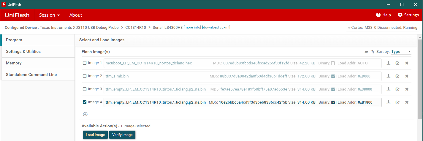
Program secondary slot 2.#
After Uniflash has finished programming the device, press the reset button on the board. You should see the following happening:
When MCUBoot starts running, the red LED is lit. The green LED will blink three times to indicate boot was successful.
When MCUBoot has finished running it will boot into the secure image.
When the secure image has finished the initializing code, it will pass control to the tfm_empty application. At this point the red LED will start blinking with 5 s interval, which should be easy to distinguish from the 1 s interval of the tfm_empty 1.0.0 image.
We have used MCUBoot to move an non-secure image from Secondary slot 2 to Primary slot 2 and run it.