Over the Air Download#
Texas Instruments
2 hours read
This module covers the basics of the TI Proprietary RF OAD (Over the Air Download) and leads you through an example. It is assumed that the reader is familiar with the SimpleLink™ TI Proprietary RF Basic RX and TX and has a basic knowledge of general C programming concepts. This lab is intended as a starting point for users who want to get familiar with OAD concepts and performing a firmware update.
Introduction#
OAD refers to the ability for an application to download a new executable image, over the air. A number of software components are involved in this process and TI uses OAD to refer to all of them as a software system.
This lab will cover an overview of a TI Proprietary RF image and examine the
high-level anatomy of an OAD image. The first task will be to setup the
environment to enable OAD. The next task will be performing the OAD firmware
update.
First you need to decide what type of OAD you want to use. You have the choice between off-chip OAD and on-chip OAD. Off-chip OAD allocates a buffer on off-chip flash memory to store the incoming image. On-chip OAD allocates the same buffer on spare on-chip memory. Make sure that your hardware supports the chosen type of OAD.
Additionally, you also need to decide which Bootloader you want to use. In this example you can choose to either use Boot Image Manager (BIM) (BIM documentation) or MCUBoot (MCUBoot documentation). The BIM bootloader is a proprietary bootloader created by TI and it was implemented for all the devices shown in the chapter Hardware. MCUBoot on the other hand side is an open source implementation of a bootloader and if you have the choice it is also the preferred solution to use. Note, that the MCUBoot example shown in this lab currently supports on-chip OAD only.
During the lab you’ll often find the following switch options. This is because the lab covers both on-chip and off-chip OAD. Please make sure you always select the option you need. The default selection is the MCUBoot based on-chip OAD and the selected case is always highlighted in red.
This content will be related to MCUBoot based on-chip OAD applications.
This content will be related to BIM based on-chip OAD applications.
This content will be related to BIM based off-chip OAD applications.
Warning
Do not mix MCUBoot and BIM based images as well as on-chip images with an off-chip setup and vice versa as this will lead to a failing boot up.
Prerequisites#
For this lab you need the specified hardware and software.
Hardware#
You need two LaunchPad boards with support for ProprietaryRF. Supported devices are:
These devices are interchangeable in the lab.
Software for desktop development#
Python v.3.6.8 or later (including pip)
Code Composer Studio (CCS) installed with support for CC13xx/CC26xx devices
Recommended reading#
Hint
The SimpleLink™ Proprietary RF OAD User’s Guide has dedicated sections about the BIM and MCUBoot based OAD. In here you will find more details about the OAD.
Anatomy of OAD#
This section explains the components involved in the OAD update process. We start by introducing the terms OAD Target (OAD Client) and OAD Distributor (OAD Server).
The OAD Target (OAD Client) is the device that receives the incoming image over the air. It is responsible for implementing the functionality for receiving OAD image data. In this lab a TI LaunchPad is used as the OAD Client.
The OAD Distributor (OAD Server) is responsible for fragmenting the new firmware image into protocol stack specific packets and sending them over the air. Below it is illustrated how you will use it in this lab. A TI LaunchPad serves as OAD Sever.
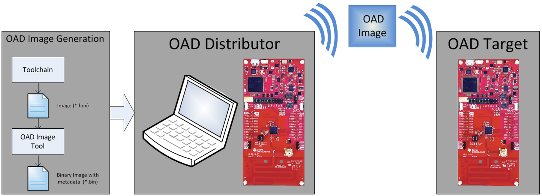
OAD Distributor (Host computer + LaunchPad) and OAD Target (LaunchPad)#
Default Non OAD Image#
We will begin with the template for a standard TI image that does not have OAD enabled.

Image without OAD#
There are three main components of this image:
The CCFG, which contains chip configuration parameters, see the Technical Reference Manual
The instructions/constants that implement the compiled form of the program (application code)
The reset vectors in the ARM Cortex M format (which are always found at the beginning of the flash): ARM Cortex M4F Vector Table
These three components are required for any image that is to run on the CC13xx or CC26xx. The goal of OAD is to get an executable image of this form on the device via an over the air update, no JTAG or wires required.
However, in order to achieve the goal of making the image pictured above upgradeable over the air, a few software components must be set in place.
Bootloader and OAD Image Header#
A running image cannot update itself. This means that the incoming OAD image must be stored in a secondary location while it is being received. MCUBoot on-chip OAD allocates spare on-chip flash memory as a buffer to store the incoming image, while BIM off-chip OAD allocates this same buffer on off-chip flash memory. BIM on-chip OAD uses a slightly different approach based on two images. The first image is containing the user application, while the second image contains a persistant application used for the OAD process. During an OAD, the persistant image will handle the OAD packet transfer and overwrite the user application image.
After the download is complete, a reboot is required. During the reboot some code must determine if the new image is valid. On MCUBoot and BIM off-chip it will also be checked if the current image should be overwritten. Finally, it has to execute the new image.
Therefore, a Bootloader is used, which in this lab is either MCUBoot or BIM.
The bootloader is intended to permanently remain on the device, meaning it persists through many OADs and cannot be updated.
The bootloader will run every time the device boots and determine if a new image should be loaded and run (based on the image header).
The bootloader and the CCFG structure are tied together, because both are required for a successful device boot.
On reset, the software in the ROM of the CC13xx or CC26xx will execute basic
startup routines, and then jump to the location of the interrupt vector table.
This location is defined in the CCFG’s IMAGE_VALID_CONF field and is part of
the bootloader image.
From there MCUBoot or BIM will determine and load the optimal image based on the OAD image header containing the version number of the image.
The bootloader code will require more reserved space in the system. See below for the memory map after the bootloader has been added to the last image.

Image with Header and MCUBoot#
Note
The bootloader project and the application project are responsible for linking and defining the CCFG structure, instead of the application as in the non OAD case. This ensures that the device will always execute the bootloader after boot.
Any modifications of the CCFG must be made in the MCUBoot or BIM project.
OAD Memory Layout#
The final memory structure depends on the type of OAD in use. On-chip OAD allocates spare on-chip flash memory as a buffer to store the incoming image firmware upgrade. Off-chip OAD allocates this same buffer on off-chip flash memory.
This section will describe the method for placing images in internal flash when using on-chip OAD together with the MCUBoot bootloader.
Warning
The MCUBoot is supported on limited devices only. Checkout the “Prerequisites” section above to see which devices are supported.
Requirements and Constraints for On-Chip OAD
In order to perform an on-chip OAD the target system must have:
The user application must be sufficiently small to fit into the flash layout system described below.
Internal Flash Memory Layout
The internal flash of the device contains the MCUBoot application as well the
active user application. Additionally, it also has a slot for a second image,
which will be used to store the new image received over the OAD. The active
image in the first slot is called primary image, while the second image is
called secondary image. The MCUBoot image header is used to determine the
image version, as explained above and the MCUBoot Trailer contains metadata
needed for the image swap process.
Once OAD is initiated by the distributor, the new image is written into the
secondary slot. When the system reboots, the MCUBoot application decides based
on the version number of the secondary image whether to boot into the new image.
If the secondary image has a higher version number than the primary image, the
secondary image is copied into the primary slot and the device boots into this
image. The right column of the image below refers to the memory address used
later on in the section Setup the Bootloader.
Warning
The addresses differ between CC13x4 or CC26x4 devices and CC13x2x7 or CC26x2x7 devices. Make sure to use the correct values later on in the section Setup the Bootloader.
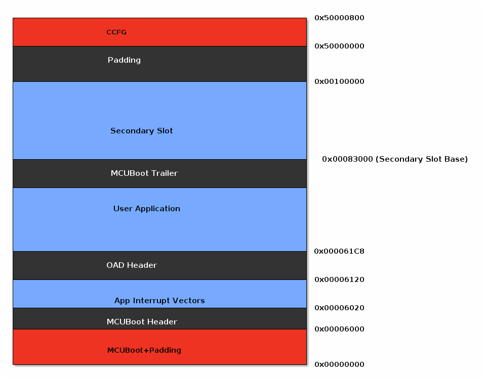
On-chip OAD flash layout of CC13x4 and CC26x4 devices#
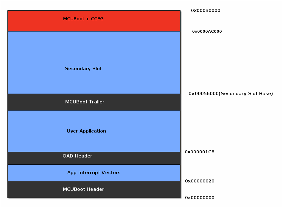
On-chip OAD flash layout of CC13x2x7 and CC26x2x7 devices#
This section will describe the method for placing images in internal flash when using on-chip OAD together with the BIM bootloader.
Warning
The BIM bootloader is supported on limited devices only. Checkout the “Prerequisites” section above to see which devices are supported.
Requirements and Constraints for On-Chip OAD
In order to perform an on-chip OAD the target system must have:
The user application must be sufficiently small to fit into the flash layout system described below.
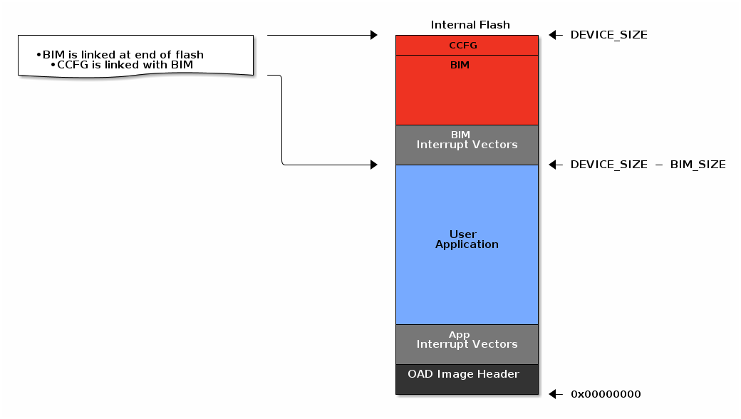
Internal Flash Memory Layout
The internal flash of the device contains the BIM bootloader, the
user application (UApp) and the persistent application (PApp). The UApp
is the application which is meant to run the code created by the end user,
while the PApp is used for the OAD process. When performing an OAD,
only the UApp is being updated while both BIM and PApp remain unchanged on the
OAD target. The image header of the UApp is used to determine the image
version, similar as explained above for MCUBoot. Once OAD is initiated by the
OAD server, the target system switches over to the PApp. From here, the data
transmission is started and the PApp is overwriting the old UApp with the new
one while it is being received. After the OAD is done, the target reboots and
BIM will validate the received UApp image and execute the UApp.
Warning
The addresses differ between CC13x1, CC13x2, CC26x1 or CC26x2 devices and CC13x2x7 or CC26x2x7 devices. Make sure to use the correct values later on in the section Setting up the OAD Client
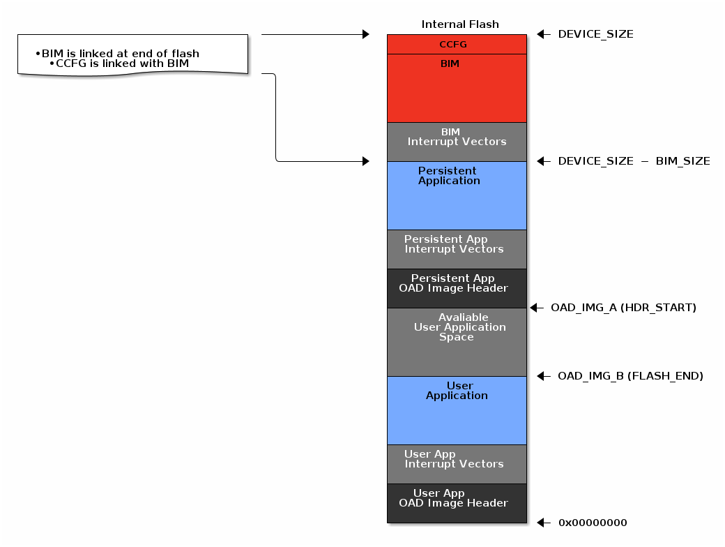
On-chip OAD flash layout using BIM#
This section will describe the method for placing images in external flash when using off-chip OAD together with the BIM bootloader.
Warning
The BIM bootloader is supported on limited devices only. Checkout the “Prerequisites” section above to see which devices are supported.
Requirements and Constraints for Off-Chip OAD
Internal flash refers to the flash memory inside the CC13xx or CC26xx and
external flash refers to an external flash memory connected to the CC13xx or
CC26xx via SPI.
In order to perform an off-chip OAD the target system must have:
An off-chip flash storage as large as the application size + one external flash page to store the external flash image header.
A serial connection (SPI) is used to communicate with the off-chip flash component.
Free GPIO pins to interface to the external memory (i.e. 4 wires for SPI)
Enough free code space to reserve the entire contents of the last 1-2 flash page(s) for BIM
Internal Flash Memory Layout
The internal flash of the device contains the active user application and the
BIM application. Off-chip OAD maximizes the available flash space to the
user application because of its ability to store the incoming image in external
flash during the download process.
Off-chip OAD Image Internal#
The user application pictured above is responsible for the following:
Implementing the software specific implementation of the OAD transport.
Finding a suitable location in external flash for the image and storing its image header in the table.
External Flash Memory Layout
The off-chip flash memory on the CC13xx or CC26xx LaunchPad contains the image
header vector table and the user applications. The memory map layout of the
external flash part is defined in ext_flash_layout.h. The amount of space
reserved for each application is sized by the user application’s implementation
of the OAD protocol. The size of the image in external flash can
be determined once the image header vector is sent over the air.
When the system reboots, BIM decides based on the version number of the
external image, whether or not to copy it into the internal flash. After that,
it will boot the image placed on the internal flash.
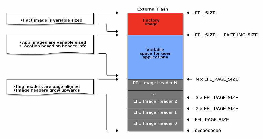
Off-chip OAD Image External#
Getting started – Desktop#
In the next step, you import the software projects used in the lab. Then, you will adjust the settings and afterward you’re ready to compile the projects.
Import Software Projects#
MCUBoot project: The project will use the
mcubootproject that supports OAD. It is found in themcubootexamples folder:
<SDK_INSTALL_DIR>\examples\nortos\<BOARD_NAME>\mcuboot\mcubootOAD Server: The example will use the
rfODADServerproject to create the server for the OAD update. It is found in theprop_rfexamples folder:
<SDK_INSTALL_DIR>\examples\rtos\<BOARD_NAME>\prop_rf\rfOADServer\tirtos7OAD Client On-Chip: The
rfODADClientproject will be used to create two versions of the firmware for the client, which will be updated via OAD. It is found in theprop_rfexamples folder:
<SDK_INSTALL_DIR>\examples\rtos\<BOARD_NAME>\prop_rf\rfOADClient\tirtos7
BIM On-Chip project: The project will use the
bim_onchipproject that supports OAD. It is found in thebimexamples folder:
<SDK_INSTALL_DIR>\examples\nortos\<BOARD_NAME>\bim\bim_onchipOAD Server: The example will use the
rfODADServerproject to create the server for the OAD update. It is found in theprop_rfexamples folder:
<SDK_INSTALL_DIR>\examples\rtos\<BOARD_NAME>\prop_rf\rfOADServer\tirtos7OAD Client PApp: The
rfOADClientIntFlashPAppproject will create the “Persistent App” firmware for the client, which will not be updated with the OAD update. It is found in theprop_rfexamples folder:
<SDK_INSTALL_DIR>\examples\rtos\<BOARD_NAME>\prop_rf\rfOADClientIntFlashPApp\tirtos7OAD Client UApp: The
rfOADClientIntFlashUAppproject will be used to create two versions of the “User App” firmware for the client, which will be updated via OAD. It is found in theprop_rfexamples folder:
<SDK_INSTALL_DIR>\examples\rtos\<BOARD_NAME>\prop_rf\rfOADClientIntFlashUApp\tirtos7
BIM Off-Chip project: The project will use the
bim_offchipproject that supports OAD. It is found in thebimexamples folder:
<SDK_INSTALL_DIR>\examples\nortos\<BOARD_NAME>\bim\bim_offchipOAD Server: The example will use the
rfODADServerproject to create the server for the OAD update. It is found in theprop_rfexamples folder:
<SDK_INSTALL_DIR>\examples\rtos\<BOARD_NAME>\prop_rf\rfOADServer\tirtos7OAD Client Off-Chip: The
rfOADClientExtFlashproject will be used to create two versions of the firmware for the client, which will be updated via OAD. It is found in theprop_rfexamples folder:
<SDK_INSTALL_DIR>\examples\rtos\<BOARD_NAME>\prop_rf\rfOADClientExtFlash\tirtos7
Hint
The directories and commands in this lab contain placeholders such as
<SDK_INSTALL_DIR> or <BOARD_NAME> which need to be replaced with you
individual setup.
Setup the Bootloader#
The first step is to define the size of the primary and secondary slot within the MCUBoot Project.
Open the file
<mcuboot_project>/flash_map_backend/flash_map_backend.hChange the values of
BOOT_PRIMARY_1_SIZEandBOOT_SECONDARY_1_SIZEto the shown values:#define BOOT_PRIMARY_1_SIZE 0x0000D000 #define BOOT_SECONDARY_1_SIZE 0x0000D000
Hint
Code Composer Studio will gray out the variables used for other platforms than the one you are using. Hence, you only need to add these values for your device only.
The base addresses of the slots are depending of the device family you are using.
If you are using a CC13x2x7 or CC26x2x7 device, use the following values:
#define BOOT_PRIMARY_1_BASE_ADDRESS         0x00000000
#define BOOT_SECONDARY_1_BASE_ADDRESS       0x00056000
If you are using a CC13x4 or CC26x4 device, use the following values:
#define BOOT_PRIMARY_1_BASE_ADDRESS         0x00006000
#define BOOT_SECONDARY_1_BASE_ADDRESS       0x00083000
Then you need to set the upgrade mode of MCUBoot to
overwrite only. For this step open the file<mcuboot_project>/mcuboot_config/mcuboot_config.hand uncommentMCUBOOT_OVERWRITE_ONLYand commentMCUBOOT_DIRECT_XIPout:#define MCUBOOT_OVERWRITE_ONLY // #define MCUBOOT_DIRECT_XIP
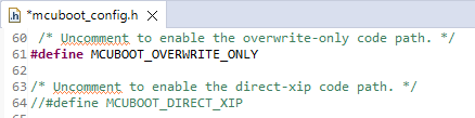
Code after setting the MCUBoot upgrade mode to overwrite only within the file mcuboot_config.h#
Hint
There are two defines for #define MCUBOOT_OVERWRITE_ONLY within that file. But only the one with the comment above it, as shown in the picture above, is being used in this lab. The second define can be left as it is, as it is used only when a project utilizes more than one MCUBoot image, which is not the case in this lab.
For more information about MCUBoot you can have a look at the following chapter Bootloader and OAD image header or at the MCUBoot documentation.
Hint
If you have difficulties to find the
#defineyou can use the file search in CCS which you can access by the shortcutctrl + f.
The first step is to select the correct Build Configuration. To do so, go
to the Project Explorer and click onto the folder of the bim_onchip project
with a right click. Then go to Build Configurations -> Set Active and
select Debug_unsecure.
The first step is to select the correct Build Configuration. To do so, go
to the Project Explorer and click onto the folder of the bim_onchip project
with a right click. Then go to Build Configurations -> Set Active and
select Debug_unsecure.
Build Software Projects#
To build a project, first select the desired project in the Project Explorer of Code Composer Studio. This will highlight the project and print Active as well as the selected Build Configuration next to the name as shown in the picture below. Then click on the hammer icon to compile the selected project.
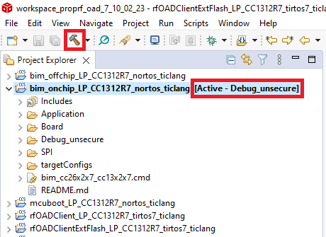
Build the project by clicking on the hammer icon#
Hint
The picture above is just an example. Make sure to select the correct project when building it.
Task 1 – Setting up the OAD Environment#
This task will lead you through the setup steps that are required to perform an OAD using the example.
Creating the Firmware Images for the Client#
To create the firmware images for the OAD client, switch to the project
rfODADClientwhich was imported earlier. At first, set the correct MCUBoot slot size in this file:<rfOADClient>/oad/native_oad/oad_config.h. Note, that this value must match the value defined in themcubootproject earlier.#define MCUBOOT_SLOT_SIZE 0x0000D000Now the image can be built by clicking on the hammer icon again. Ensure, that the
rfODADClientproject is active in order to build the correct image.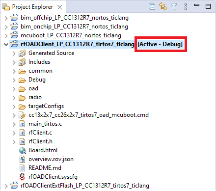
Select the active project in the Project Explorer#
The next step is to create two signed images with the version 1.0.0 and version 2.0.0 based on the image just created by the
rfODADClientproject. To do so, open the Command Prompt of your PC and navigate to this directory:<SDK_INSTALL_DIR>/tools/common/mcubootHint
On Windows you can navigate to the directory using the File Explorer and open that directory within the Command Prompt by clicking into the file path, write
cmdin here and hit the enter key.From this directory you can run the imgtool with the following arguments to create the two images.
Create signed image version 1.0.0
imgtool.exe sign --header-size 0x20 --align 4 --slot-size 0xD000 --pad --version 1.0.0 --pad-header --key <SDK_INSTALL_DIR>/source/third_party/mcuboot/root-ec-p256.pem <CCS_WORKSPACE>\rfOADClient_<PLATFORM>_tirtos7_ticlang\Debug\rfOADClient_<PLATFORM>_tirtos7_ticlang.hex <CCS_WORKSPACE>\rfOADClient_<PLATFORM>_tirtos7_ticlang\Debug\rfOADClient_<PLATFORM>_tirtos7_ticlang_signed_v1.hex
Create signed image version 2.0.0
imgtool.exe sign --header-size 0x20 --align 4 --slot-size 0xD000 --pad --version 2.0.0 --pad-header --key <SDK_INSTALL_DIR>/source/third_party/mcuboot/root-ec-p256.pem <CCS_WORKSPACE>\rfOADClient_<PLATFORM>_tirtos7_ticlang\Debug\rfOADClient_<PLATFORM>_tirtos7_ticlang.hex <CCS_WORKSPACE>\rfOADClient_<PLATFORM>_tirtos7_ticlang\Debug\rfOADClient_<PLATFORM>_tirtos7_ticlang_signed_v2.hex
Example:
imgtool.exe sign --header-size 0x20 --align 4 --slot-size 0xD000 --pad --version 1.0.0 --pad-header --key C:\ti\simplelink_cc13xx_cc26xx_sdk_7_10_02_23/source/third_party/mcuboot/root-ec-p256.pem C:\Users\username\workspace\rfOADClient_LP_CC1312R7_tirtos7_ticlang\Debug\rfOADClient_LP_CC1312R7_tirtos7_ticlang.hex C:\Users\username\workspace\rfOADClient_LP_CC1312R7_tirtos7_ticlang\Debug\rfOADClient_LP_CC1312R7_tirtos7_ticlang_signed_v1.hex
After running the scripts, you can Refresh the Project Explorer by right clicking in the Project Explorer and clicking on Refresh or by hitting the F5 key on the keyboard. Now you should see the two signed images in this directory:
<rfOADClient>/Debug
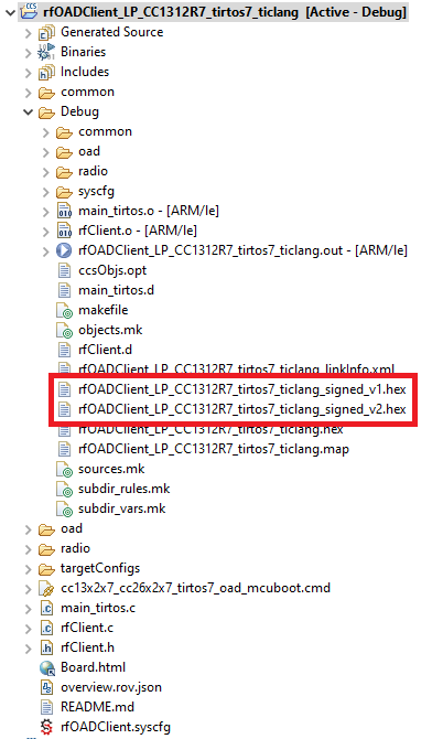
The signed images created by the imgtool#
At this point you have the three images needed for the OAD:
MCUBoot image
Client image version 1.0.0
Client image version 2.0.0
As mentioned in the chapter OAD Memory Layout, you need the user application (UApp) as well as the persistent application (PApp). In this chapter you create a version 1.0.0 and version 2.0.0 of the UApp as well as the image for the PApp. But let’s start with the UApp first:
Creating Images for the UApp:
To create the firmware images for the UApp, switch to the project
rfOADClientIntFlashUAppwhich was imported earlier. After selecting it, you can build it by clicking on the hammer icon again.The next step is to create two signed images with the version 1.0.0 and version 2.0.0 based on the image just created by the
rfOADClientIntFlashUAppproject. To do so, open the Command Prompt of your PC and navigate to this directory:<SDK_INSTALL_DIR>/tools/common/oadHint
On Windows you can navigate to the directory using the File Explorer and open that directory within the Command Prompt by clicking into the file path, write
cmdin here and hit the enter key.From this directory you can run the oad_image_tool with the following arguments to create the image version 1.0.0:
oad_image_tool.exe -hex1 <CCS_WORKSPACE>\rfOADClientIntFlashUApp_<PLATFORM>_tirtos7_ticlang\Debug\rfOADClientIntFlashUApp_<PLATFORM>_tirtos7_ticlang.hex -o <CCS_WORKSPACE>\rfOADClientIntFlashUApp_<PLATFORM>_tirtos7_ticlang\Debug\rfOADClientIntFlashUApp_<PLATFORM>_tirtos7_ticlang_signed_v1 -k private.pem ccs output_directory 7
Example:
oad_image_tool.exe -hex1 C:\Users\username\workspace\rfOADClientIntFlashUApp_LP_CC1312R7_tirtos7_ticlang\Debug\rfOADClientIntFlashUApp_LP_CC1312R7_tirtos7_ticlang.hex -o C:\Users\username\workspace\rfOADClientIntFlashUApp_LP_CC1312R7_tirtos7_ticlang\Debug\rfOADClientIntFlashUApp_LP_CC1312R7_tirtos7_ticlang_signed_v1 -k private.pem ccs output_directory 7
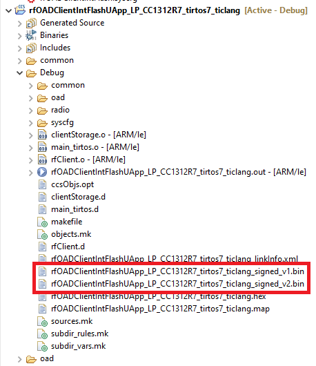
After running the scripts, you can Refresh the Project Explorer by right clicking in the Project Explorer and clicking on Refresh or by hitting the F5 key on the keyboard. Now you should see the signed images v1 in this directory:
<rfOADClientIntFlashUApp>/Debug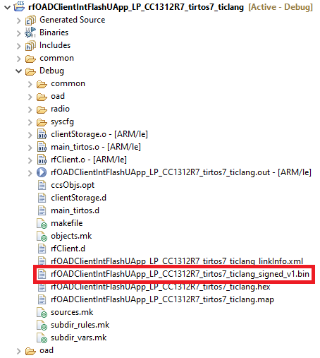
Select the active project in the Project Explorer#
To change the version for the second image you need to open this file:
<rfOADClientIntFlashUApp>/oad/native_oad/oad_image_header_app.c. Then go to #define SOFTWARE_VER and change it to version 2.#define SOFTWARE_VER {'0', '0', '0', '2'}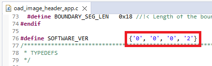
The version number for the image v2 defined in the file oad_image_header_app.c#
Hint
If you have difficulties to find the
#defineyou can use the file search in CCS which you can access by the shortcutctrl + f.Now click on the hammer icon again, to build the image version 2.0.0.
Once building is done, you need to switch back to the Command Prompt of you PC to run the oad_image_tool from step 2 again to create a signed image. But notice, that the command is slightly different to the one from step 3, as this time the output file will end with the name “*_v2”.
oad_image_tool.exe -hex1 <CCS_WORKSPACE>\rfOADClientIntFlashUApp_<PLATFORM>_tirtos7_ticlang\Debug\rfOADClientIntFlashUApp_<PLATFORM>_tirtos7_ticlang.hex -o <CCS_WORKSPACE>\rfOADClientIntFlashUApp_<PLATFORM>_tirtos7_ticlang\Debug\rfOADClientIntFlashUApp_<PLATFORM>_tirtos7_ticlang_signed_v2 -k private.pem ccs output_directory 7
Refresh the Project Explorer as shown at step 4 and check if you have both images as shown below:
Select the active project in the Project Explorer#
Creating Images for the PApp:
To create the firmware images for the PApp, switch to the project
rfOADClientIntFlashPAppwhich was imported earlier. After selecting it, you can build it by clicking on the hammer icon again.Similar to the UApp also the PApp needs to be signed with the help of the oad_image_tool from Creating Images for the UApp step 2. For this switch to the Command Prompt and run the following command. Note, that the arguments are different than on step 3 and 7.
oad_image_tool.exe -hex1 <CCS_WORKSPACE>\rfOADClientIntFlashPApp_<PLATFORM>_tirtos7_ticlang\Debug\rfOADClientIntFlashPApp_<PLATFORM>_tirtos7_ticlang.hex -o <CCS_WORKSPACE>\rfOADClientIntFlashPApp_<PLATFORM>_tirtos7_ticlang\Debug\rfOADClientIntFlashPApp_<PLATFORM>_tirtos7_ticlang_signed -k private.pem ccs output_directory 0
At this point you have the four images needed for the OAD:
BIM image
Client UApp image version 1.0.0
Client UApp image version 2.0.0
Client PApp image
To create the firmware images for the OAD client, switch to the project
rfOADClientExtFlashwhich was imported earlier. After selecting it, you can build it by clicking on the hammer icon again.The next step is to create two signed images with the version 1.0.0 and version 2.0.0 based on the image just created by the
rfOADClientExtFlashproject. To do so, open the Command Prompt of your PC and navigate to this directory:<SDK_INSTALL_DIR>/tools/common/oadHint
On Windows you can navigate to the directory using the File Explorer and open that directory within the Command Prompt by clicking into the file path, write
cmdin here and hit the enter key.From this directory you can run the oad_image_tool with the following arguments to create the image version 1.0.0:
oad_image_tool.exe -hex1 <CCS_WORKSPACE>\rfOADClientExtFlash_<PLATFORM>_tirtos7_ticlang\Debug\rfOADClientExtFlash_<PLATFORM>_tirtos7_ticlang.hex -o <CCS_WORKSPACE>\rfOADClientExtFlash_<PLATFORM>_tirtos7_ticlang\Debug\rfOADClientExtFlash_<PLATFORM>_tirtos7_ticlang_signed_v1 -k private.pem ccs output_directory 7
Example:
oad_image_tool.exe -hex1 C:\Users\username\workspace\rfOADClientExtFlash_LP_CC1312R7_tirtos7_ticlang\Debug\rfOADClientExtFlash_LP_CC1312R7_tirtos7_ticlang.hex -o C:\Users\username\workspace\rfOADClientExtFlash_LP_CC1312R7_tirtos7_ticlang\Debug\rfOADClientExtFlash_LP_CC1312R7_tirtos7_ticlang_signed_v1 -k private.pem ccs output_directory 7
After running the scripts, you can Refresh the Project Explorer by right clicking in the Project Explorer and clicking on Refresh or by hitting the F5 key on the keyboard. Now you should see the signed images v1 in this directory:
<rfOADClientExtFlash>/Debug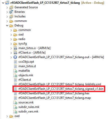
Select the active project in the Project Explorer#
To change the version for the second image you need to open this file:
<rfOADClientExtFlash>/oad/native_oad/oad_image_header_app.c. Then go to #define SOFTWARE_VER and change it to version 2.#define SOFTWARE_VER {'0', '0', '0', '2'}
The version number for the image v2 defined in the file oad_image_header_app.c#
Hint
If you have difficulties to find the
#defineyou can use the file search in CCS which you can access by the shortcutctrl + f.Now click on the hammer icon again, to build the image version 2.0.0.
Once building is done, you need to switch back to the Command Prompt of you PC to run the oad_image_tool from step 2 again to create a signed image. But notice, that the command is slightly different to the one from step 3, as this time the output file will end with the name “*_v2”.
oad_image_tool.exe -hex1 <CCS_WORKSPACE>\rfOADClientExtFlash_<PLATFORM>_tirtos7_ticlang\Debug\rfOADClientExtFlash_<PLATFORM>_tirtos7_ticlang.hex -o <CCS_WORKSPACE>\rfOADClientExtFlash_<PLATFORM>_tirtos7_ticlang\Debug\rfOADClientExtFlash_<PLATFORM>_tirtos7_ticlang_signed_v2 -k private.pem ccs output_directory 7
Refresh the Project Explorer as shown at step 4 and check if you have both images as shown below:
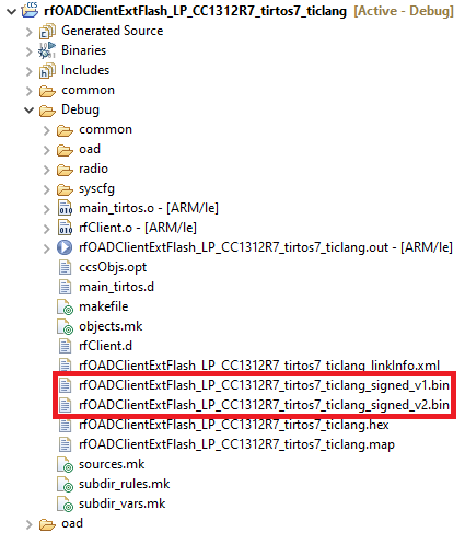
Select the active project in the Project Explorer#
At this point you have the three images needed for the OAD:
BIM image
Client image version 1.0.0
Client image version 2.0.0
Setting up the OAD Client#
To flash the images onto the OAD Client, open the program UNIFLASH. At this point you have to decide which of your two LaunchPads will be used as the OAD Server and the OAD Client. In order to distinguish both bards from each other, it is recommended to take a sticky note on which you write down the role you assigned to the LaunchPad as well as its serial number. To find out the serial number of each board, connect only one of your boards to your PC. If you now open UniFlash, you can see the serial number listed below your device. Do this with both boards, as you will need the serial number for the OAD Server later on.
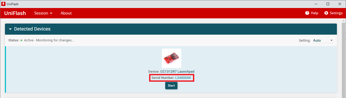
Uniflash showing the serial number of the LaunchPad#
Now that you have defined which LaunchPad is used as the OAD Client and OAD Server, you can connect both LaunchPads to your PC. Next, go to UniFlash and click on the Start button under the LaunchPad you defined as your OAD Client. The OAD Client will need the image of MCUBoot as well as the Client image version 1.0.0. To load them, click on the Browse button and navigate to the directories shown below. After loading the MCUBoot image, click on the plus symbol under the first image to select the second image.
MCUBoot:
<CCS_WORKSPACE>\mcuboot_<PLATFORM>_nortos_ticlang\Debug\mcuboot_LP_CC1312R7_nortos_ticlang.hexClient image version 1.0.0:
<CCS_WORKSPACE>\rfOADClient_<PLATFORM>_tirtos7_ticlang\Debug\rfOADClient_<PLATFORM>_tirtos7_ticlang_signed_v1.hex
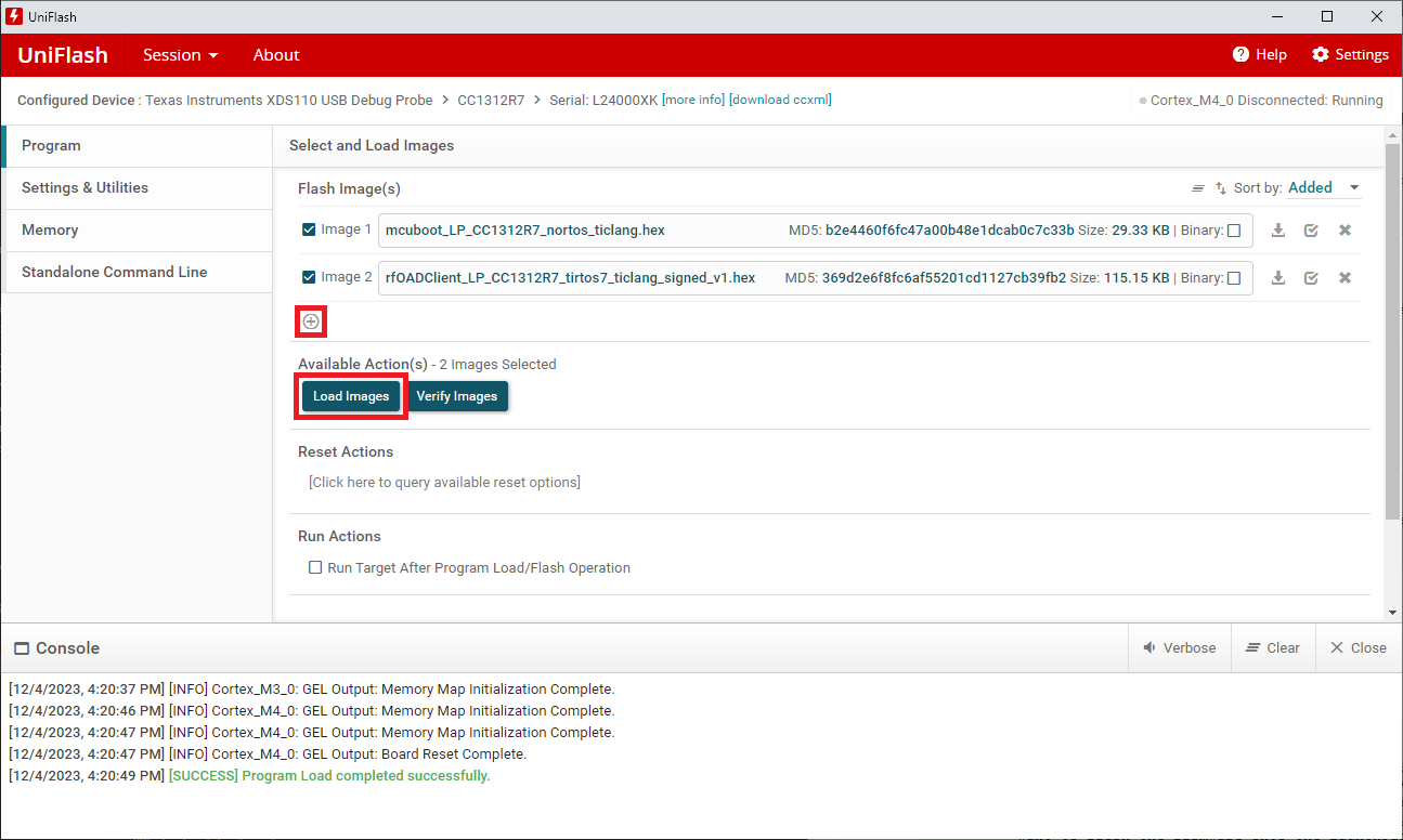
Uniflash with both images ready to be flashed onto the LaunchPad#
Once both images are selected click on Load Images to flash both of them onto the LaunchPad. After the programming is done, you need to manually reset the LaunchPad by pushing the RESET button. The OAD Client is now set up completely.
Warning
Make sure to reset the LaunchPad after the programming with Uniflash to ensure the firmware is running.
Now that you have defined which LaunchPad is used as the OAD Client and OAD Server, you can connect both LaunchPads to your PC. Next, go to UniFlash and click on the Start button under the LaunchPad you defined as your OAD Client. The OAD Client will need the image of BIM, UApp version 1.0.0 as well as the PApp. To load them, click on the Browse button and navigate to the directories shown below. After loading the BIM image, click on the plus symbol under the first image to select the second image.
BIM On-Chip:
<CCS_WORKSPACE>\bim_onchip_<PLATFORM>_nortos_ticlang\Debug_unsecure\bim_onchip_<PLATFORM>_nortos_ticlang.hexClient UApp image version 1.0.0:
<CCS_WORKSPACE>\rfOADClientIntFlashUApp_<PLATFORM>_tirtos7_ticlang\Debug\rfOADClientIntFlashUApp_<PLATFORM>_tirtos7_ticlang_signed_v1.binClient PApp image:
<CCS_WORKSPACE>\rfOADClientIntFlashPApp_<PLATFORM>_tirtos7_ticlang\Debug\rfOADClientIntFlashPApp_<PLATFORM>_tirtos7_ticlang_signed.bin
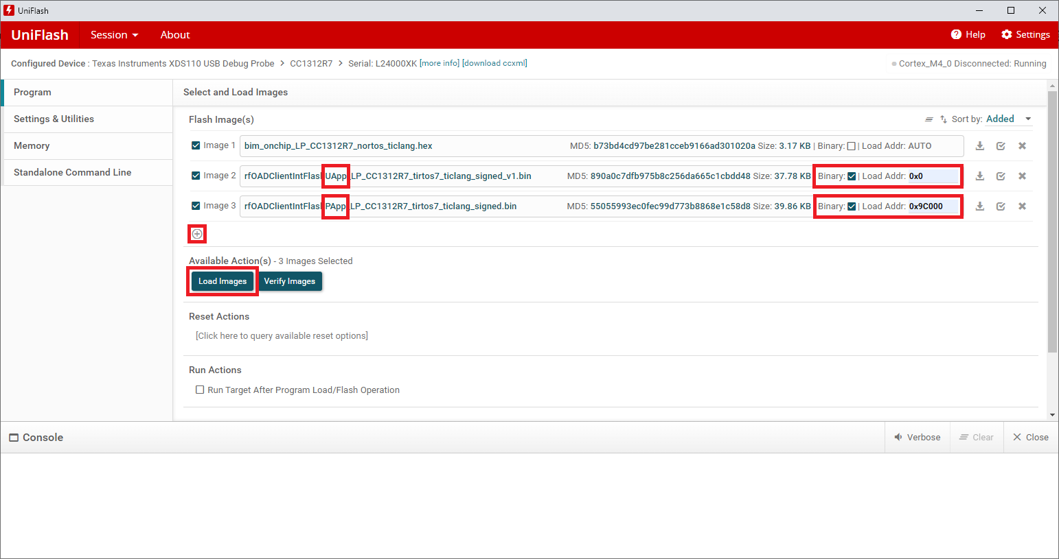
Uniflash with all three images ready to be flashed onto the LaunchPad#
After selecting all three images in UniFlash, you need to set the Load Address for the UApp and PApp. This will define at which address the image will be written to. As mentioned in chapter OAD Memory Layout, these addresses vary between devices. Therefore, make sure you are using the correct values for the Load Address:
Load Address for the UApp image:
0x0Load Address for the PApp image on CC13x1, CC13x2, CC26x1 and CC26x2 devices:
0x44000Load Address for the PApp image on CC13x2x7 and CC26x2x7 devices:
0x9C000
Next, click on Load Images to flash all three images onto the LaunchPad. After the programming is done, you need to manually reset the LaunchPad by pushing the RESET button. The OAD Client is now set up completely.
Warning
Make sure to reset the LaunchPad after the programming with Uniflash to ensure the firmware is running.
Now that you have defined which LaunchPad is used as the OAD Client and OAD Server, you can connect both LaunchPads to your PC. Next, go to UniFlash and click on the Start button under the LaunchPad you defined as your OAD Client. The OAD Client will need the image of BIM as well as the Client image version 1.0.0. To load them, click on the Browse button and navigate to the directories shown below. After loading the BIM image, click on the plus symbol under the first image to select the second image.
BIM Off-Chip:
<CCS_WORKSPACE>\bim_offchip_<PLATFORM>_nortos_ticlang\Debug_unsecure\bim_offchip_<PLATFORM>_nortos_ticlang.hexClient image version 1.0.0:
<CCS_WORKSPACE>\rfOADClientExtFlash_<PLATFORM>_tirtos7_ticlang\Debug\rfOADClientExtFlash_<PLATFORM>_tirtos7_ticlang_signed_v1.hex
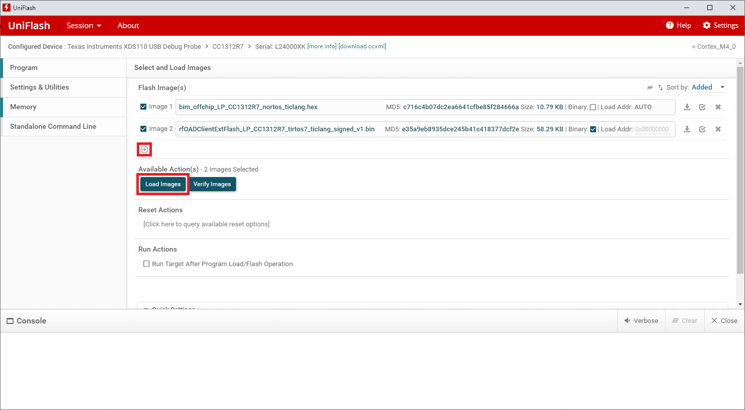
Uniflash with both images ready to be flashed onto the LaunchPad#
Once both images are selected click on Load Images to flash both of them onto the LaunchPad. After the programming is done, you need to manually reset the LaunchPad by pushing the RESET button. The OAD Client is now set up completely.
Warning
Make sure to reset the LaunchPad after the programming with Uniflash to ensure the firmware is running.
Setting up the Server#
To setup the OAD Server, open the rfODADServer project and click with a right
click onto the project folder. Then move to
Build Configurations -> Set Active and depending on which bootloader
you are using select either Debug_BIM or Debug_MCUBoot. Now click on the
hammer symbol to build the project. At this point, if you want to flash the
firmware onto the LaunchPad, Code Composer Studio does not know which board to
use and therefore it will randomly select one of them. To ensure that the
firmware will be flashed onto the LaunchPad defined as the OAD Server you can
either unplug the other LaunchPad before flashing the firmware or alternatively
assign a dedicated board to the project based on its serial number.
Hint
Make sure to select the correct Build Configuration before building and flashing the OAD Server image onto the LaunchPad. When using the worng Build Configuration the OAD may fail.
Assign project to specific LaunchPad (optional)#
Like mentioned earlier in the chapter Setting up the OAD Client LaunchPads have an individual serial number which can be read out. However, this serial number is actually from the XDS-Debugger and not to the actual CC13xx or CC26xx device itself. In Code Composer Studio you can use this serial number to decide which debugger should be used when flashing an new image. This setting needs to be selected for each project and therefore, each project has an directory called targetConfigs in which you can find an *.ccxml file. To assign an debugger to one project follow the following steps:
Open the Configuration file:
<rfOADServer>/targetConfigs/<PLATFORM>.ccxml
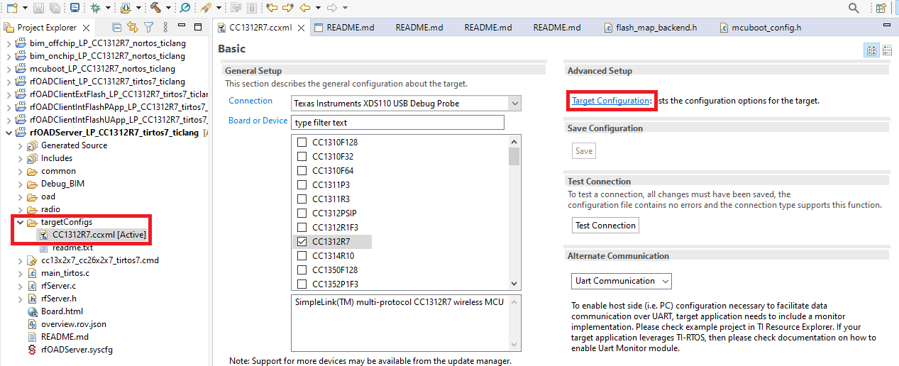
Open the configurations file#
Go to Target Configuration.
Select the debugger in the All Connections area (the root node of the list).
Go to Connection Properties and set Debug Probe Selection to Select by serial number.
Enter the serial number of your XDS debugger (If the serial number is unknown, connect your LaunchPad to your PC and open UNIFLASH. It will display the serial number below the LaunchPad).
Go to All Connections, click on Save and close the Configuration file.
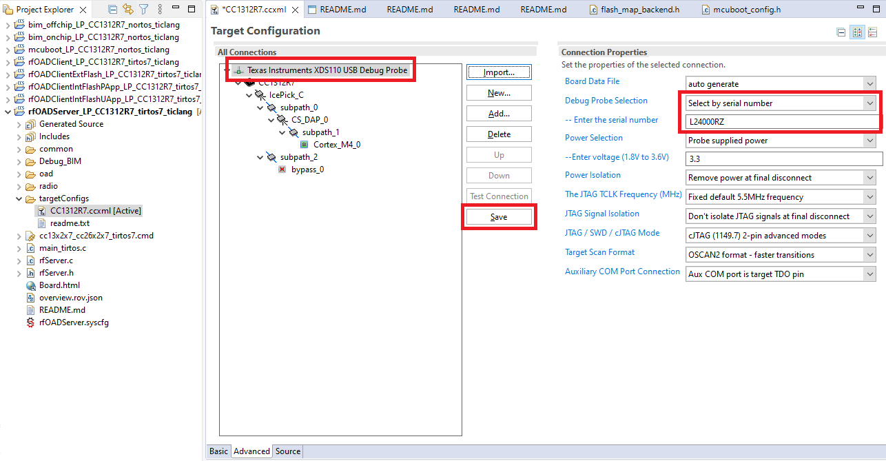
Changing the serial number under Target Configurations#
Now every time you click on the flash icon, Code Composer Studio will use this specific debugger only.
Flash the firmware onto the Server#
After the Server project has been built, it can be flashed onto the LaunchPad by clicking on the flash icon.
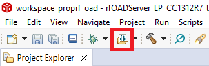
Flashing the firmware onto the device#
Upload the new Client Image to the OAD Server#
Before the OAD Server is able to perform an OAD update it needs to have the new image (version 2.0.0) for the OAD Client. The OAD Server will then store the client image on its external flash. To upload the firmware, you first need to connect to the OAD Server via UART.
Open a serial terminal or your desire (e.g. PuTTY, TeraTerm) or use the serial terminal built into Code Composer Studio. When using the terminal of Code Composer Studio, select Serial Terminal and choose the COM Port of your LaunchPad.
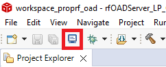
Open a serial terminal by clicking on the monitor icon#
Start the serial terminal with the following settings:
Baud-rate:      115200
Data bits:           8
Stop bits:           1
Parity:           None
Flow Control:     None
You should now see some Text from the from your LauchPad. Use the button BTN2 on your LaunchPad to cycle through the menu of the OAD Server. Navigate to Update Available FW and use the button BTN1 to activate the update process of the OAD Server.
Now disconnect your current serial terminal. On Code Composer Studio you can do this by clicking on the following icon:
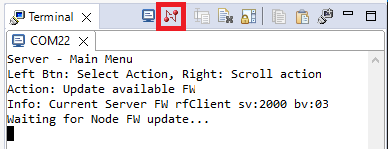
Close the serial session by clicking on the following icon#
Warning
Make sure you’ve disconnected the serial session, because otherwise the next step won’t work.
Open the Command Prompt on Windows and navigate to that directory:
<SDK_INSTALL_DIR>/tools/prop_rf/oad
Now you can upload the new OAD Client image version 2.0.0 to the OAD Server with the help of the oad_write_bin.py script. For this, replace
with the number of your COM Port e.g. COM22 and run the following command in the console: python oad_write_bin.py <COMPORT> <CCS_WORKSPACE>\rfOADClient_<PLATFORM>_tirtos7_ticlang\Debug\rfOADClient_<PLATFORM>_tirtos7_ticlang_signed_v2.hex
Example:
python oad_write_bin.py COM22 C:\Users\username\workspace\rfOADClient_LP_CC1312R7_tirtos7_ticlang\Debug\rfOADClient_LP_CC1312R7_tirtos7_ticlang_signed_v2.hex
Now you can upload the new OAD Client image version 2.0.0 to the OAD Server with the help of the oad_write_bin.py script. For this, replace
with the number of your COM Port and run the following command in the console: python oad_write_bin.py <COMPORT> <CCS_WORKSPACE>\rfOADClientIntFlashUApp_<PLATFORM>_tirtos7_ticlang\Debug\rfOADClientIntFlashUApp_<PLATFORM>_tirtos7_ticlang_signed_v2.bin
Example:
python oad_write_bin.py COM22 C:\Users\username\workspace\rfOADClientIntFlashUApp_LP_CC1312R7_tirtos7_ticlang\Debug\rfOADClientIntFlashUApp_LP_CC1312R7_tirtos7_ticlang_signed_v2.bin
Now you can upload the new OAD Client image version 2.0.0 to the OAD Server with the help of the oad_write_bin.py script. For this, replace
with the number of your COM Port and run the following command in the console: python oad_write_bin.py <COMPORT> <CCS_WORKSPACE>\rfOADClientExtFlash_<PLATFORM>_tirtos7_ticlang\Debug\rfOADClientExtFlash_<PLATFORM>_tirtos7_ticlang_signed_v2.bin
Example:
python oad_write_bin.py COM22 C:\Users\username\workspace\rfOADClientExtFlash_LP_CC1312R7_tirtos7_ticlang\Debug\rfOADClientExtFlash_LP_CC1312R7_tirtos7_ticlang_signed_v2.bin
Once the script is done, it will prompt All blocks sent which indicates that the upload was successful.
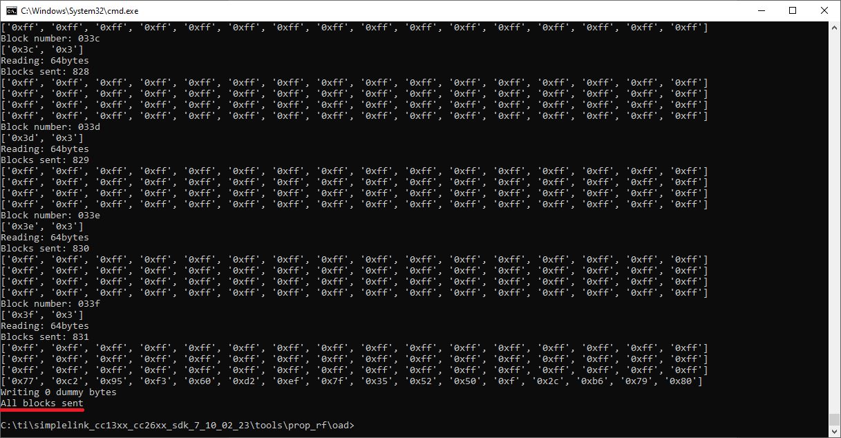
The display after a successful upload of a new image to the OAD Server#
Task 2 – Performing an OAD#
After the OAD Client image version 2.0.0 was uploaded to the OAD Server, the OAD Server can be reconnected to the serial terminal. It should now display the version of the Client image as shown in the picture below:
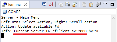
version 2.0.0#
The menu of the OAD server after the upload of the OAD client image version 2.0.0
The OAD Server has three main actions:
Update available FW is used to upload a new OAD Client image to the OAD Server
Send FW Ver Req reads out the current firmware version of the OAD Client
Update client FW initiates the OAD process
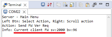
Use the button BTN2 of your LaunchPad to navigate to the action Send FW Ver Req. If you now push the BTN1 you can see, that the OAD Client is currently running the firmware version 1.0.0.
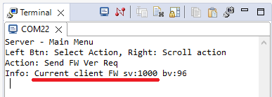
Read out the version of the image from the client#
sv: means software version, bv: stands for boot manager version.
Next, navigate to Update client FW and start the OAD process by pushing the button BTN1. You can now see the progress of the OAD process.
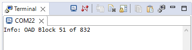
The serial console of the OAD Server during the OAD process#
When the OAD is complete, go back to the menu by pressing either BTN1 or BTN2. You can now verify that the OAD was successful by navigating to Send FW Ver Req and requesting to read back the version of the image running on the OAD Client. If you now push the BTN1 the version of the OAD Client should jump to version 2.0.0.
After the OAD the client is running the version 2.0.0#
Hint
Congratulations, you’ve done an OAD!
If you want to redo the OAD process you only need to flash the image version 1.0.0 to the OAD Client like shown in the chapter Setting up the OAD Client again. If you have UniFlash still open, all you need to do is click on the Load Images and reset the LaunchPad after the upload.