Zigbee Over-the-Air (OTA) Upgrades#
Introduction#
This module covers the basics of the Over-the-Air (OTA) upgrade feature of the TI Z-Stack. The estimated time to complete this lab is 3 hours. It is assumed that the reader has a basic knowledge of embedded C tool chains and general C programming concepts. This lab is intended as a starting point for users who want to get familiar with OTA concepts and running a basic update demo.
OTA refers to the ability for an image to download a new executable image, over the air using the Zigbee protocol stack. A number of software components are involved in this process and TI will also use OAD (Over the Air Downloads) to refer to all of them as a software system.
This module does not cover updates via UART or SPI. For more information on wired update options, see the Serial Bootloader Interface application report.
This lab will cover an overview of a typical Zigbee image and examine the high level anatomy of an OTA image. The first task will be to setup the environment to enable OAD. The next task will be running the out of the box demo for OTA using OtaServer, highlighting critical concepts along the way.
This guide will split some tasks between on-chip and off-chip OAD. These sections will look like below boxes. Please select the desired application by clicking on one of the tabs.
This content will be related to on-chip OAD applications
This content will be related to off-chip OAD applications
Warning
Do not mix on-Chip images with an Off-Chip setup and vice versa as this will lead to a failing boot up.
Prerequisites#
Hardware#
2 x Zigbee-capable SimpleLink LaunchPads for running sample applications, review the SDK Release Notes for more information. On-chip OAD is only supported by the LP-CC2652R7 or LP-CC1352P7-4.
1 x LaunchPad for packet sniffing (optional)
Micro USB Cables
These devices are interchangeable in the lab.
Software for desktop development#
Code Composer Studio (latest version) with support for CC13xx/CC26xx devices
SimpleLink CC13xx / CC26xx SDK (latest)
OtaServer (located in the
\tools\zstack\zigbee_ota_serverdirectory of the SimpleLink™ Device SDK)Optional for packet sniffing
Recommended reading#
TI Z-Stack User’s Guide Zigbee Over-The-Air Firmware Upgrade OTA/OAD Chapters
Other Zigbee SimpleLink Academy Labs#
Getting started – Desktop#
The following installation steps can be started in the background while reading the next chapter Anatomy of an OAD.
Install the Software#
Import Software Projects#
The following software projects will be used in this lab. They can be imported and compiled now.
ZR Switch Client OAD On-Chip
The project will use the zr_sw_ota_client_onchip project that
supports OAD. It is found in the zstack examples folder:
<SDK_INSTALL_DIR>\examples\rtos\<BOARD_NAME>\zstack\zr_sw_ota_client_onchip\tirtos7
Boot Image Loader (BIM)
For this lab, the project bim_onchip is required. The full project is
available in the bim examples folder:
<SDK_INSTALL_DIR>\examples\nortos\<BOARD_NAME>\bim\bim_onchip
ZR Switch Client OAD Off-Chip
The project will use the zr_sw_ota_client_offchip project that
supports OAD. It is found in the zstack examples folder:
<SDK_INSTALL_DIR>\examples\rtos\<BOARD_NAME>\zstack\zr_sw_ota_client_offchip\tirtos7
Boot Image Loader (BIM)
For this lab, the project bim_offchip is required. The full project is
available in the bim examples folder:
<SDK_INSTALL_DIR>\examples\nortos\<BOARD_NAME>\bim\bim_offchip
As detailed in the introduction, the following tasks will cover some of the primary topics related to OAD using the Z-Stack.
Anatomy of an OAD#
This section seeks to explain the various components involved in an OAD image from a high level. Each software component will be treated as a building block that is added to a vanilla (Unmodified Z-Stack application without OAD such as zr_switch) Z-Stack image to eventually build an OAD image.
Default Non OAD Image#
We will begin with the template for a standard Z-stack image that does not have OAD enabled.
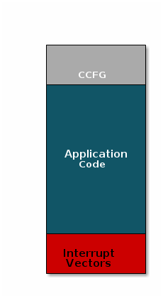
Image without OAD#
There are three main components of this image:
The instructions/constants that implement the compiled form of the program (application code)
The reset vectors in the ARM Cortex M format: ARM Cortex M4F Vector Table
The CCFG, which contains chip configuration parameters, see the Technical Reference Manual
These three components are required for any image that is to run on the CC26x2R or CC13x2R. The goal of OAD is to get an executable image of this form on the device via an over the air update, no JTAG or wires required.
However, in order to achieve the goal of making the image pictured above upgradeable over the air, a few software components must be set in place.
Image Fragmentation/ Image Header#
Even with the largest payload size supported by the Zigbee Specification, an entire CC26xx/CC13xx image cannot be sent in an single packet. This is for a number of reasons including:
TX time
Lost packet penalty
Preventing other packets from being sent
Therefore, the image to be sent over the air must be fragmented into a size that will fit into ZCL (Zigbee Cluster Library) payloads. It will take many ZCL packets to send a complete image over the air using the Zigbee protocol. Each of these packets containing OAD image information is referred to as an OAD Block.
However, how can the receiving device know information about the incoming image? This problem is solved by using the OAD Image Header. The OAD Image Header contains metadata describing the image and is used by the application and BIM to determine the suitability of an image for downloading or loading. Other benefits of the OAD Image Header are:
Image metadata is bundled as part of the image
A running image can query knowledge about itself by reading the header
Bootloader software can read the header to determine which image(s) are present and active
Information about the incoming image is available to the target early in the OAD process
Now, that we are sold on the benefits of an image header in an OAD system, here is an updated drawing of the stock image with an image header added.
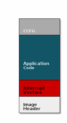
Image with Header#
Warning
When comparing images with a header and images without the header one must keep in
mind that the header itself takes up space.
The space available to the code section of the image is shrunk to accommodate
the header, and the reset vectors are pushed back to accommodate the header.
These changes are specified in the linker script (shrinking app space) and the
RTOS .cfg file (relocating reset vectors).
Boot Image Manager (BIM)#
A running image cannot update itself. This means that incoming OAD image must be stored in a temporary location while it is being received. This temporary location can be a reserved location in internal flash (i.e. on-chip OAD) outside of the executable area covered in the first image. Alternatively, the temporary location can be in an external flash chip (i.e. off-chip OAD).
After the download is complete, some code must determine if the new image is valid, and if current image should be overwritten, and finally execute the new image.
This piece of code is referred to as the Boot Image Manger (BIM) in the TI OAD solution.
BIM is intended to permanently remain on the device, meaning it persists through many OADs and cannot be updated. The BIM must therefore be changed either using JTAG programming or the serial bootloader interface if an update is necessary.
BIM will run every time the device boots and determine if a new image should be loaded and run (based on image header).
Furthermore, the BIM and CCFG structure are tied together, because both are required for a successful device boot.
The CCFG is needed by the boot ROM and startup firmware for device trim and to
determine where program execution is to start from. By default the boot ROM will
jump to address 0x00000000 and look for a vector table, but this region is
now occupied by the image header. A custom CCFG must be used to instruct the
device to jump directly to the BIM.
From there the BIM will perform device trim based on the CCFG settings, and determine and load the optimal image based on the OAD image header.
The BIM code will require more reserved space in our system. See below for the memory map after a BIM has been added to the last image.
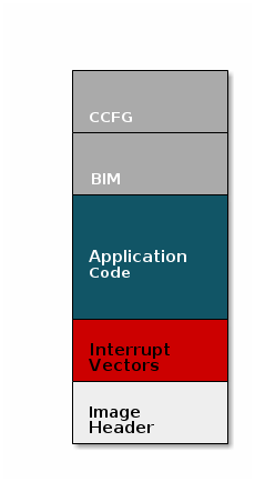
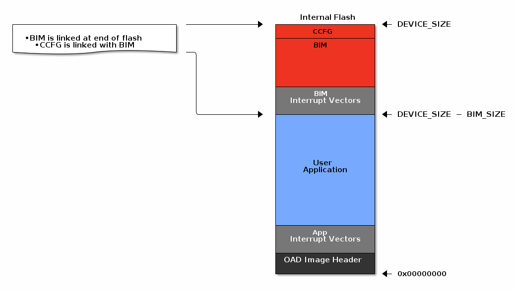
Image with Header and BIM#
Warning
The BIM is responsible for linking and defining the CCFG structure, instead of the application as in the non OAD case. This ensures that the device will always execute the BIM after boot.
OAD Memory Layout#
The final memory structure depends on the type of OAD in use.
This section will describe the method for placing images in internal flash when using on-chip OAD.
Requirements and Constraints for On-chip OAD
In order to perform an on-chip OAD the target system must ensure:
The user application must be sufficiently small in order to fit into the flash layout system described below
User app functionality is not lost while performing OAD (Dual image architecture is used so an active application is always available in case of OTA failure)
Only one user application image may be selected in flash at any time.
Internal Flash Memory Layout
The internal flash of the device contains the active user application, the user application’s stack, and the BIM. Each component’s role is defined below.
As we have assumed the stack-library approach, the stack images referenced below are a part of each application image.
Dual-Image BIM
Search for the proper image in FLASH
Copy new user image from the download application area to the active application area
Ensure validity and optional security of active image before running
Stack Library
Z-Stack protocol implementation
User Application
User defined application code
Must implement OAD reset service
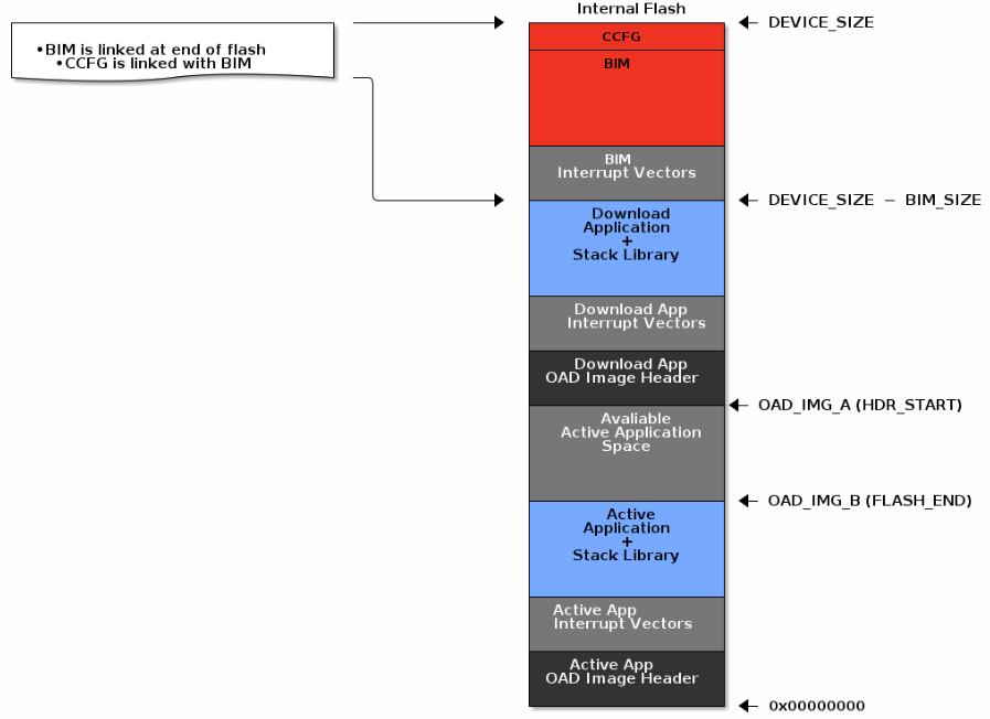
On-Chip OAD Dual Image Configuration#
The active user application (referred to as OAD_IMG_B) pictured above is
responsible for the following:
Implementing the protocol stack definition of the OAD reset service
Implementing customer defined behavior
The download application (referred to as OAD_IMG_A) pictured above is meant to
have identical responsibilities once it replaces the active application.
Warning
Once the first OAD process is completed the roles of the OAD images switch.
Thus OAD_IMG_A is now the new active user application and OAD_IMG_B becomes
the download application area. The flash area assignments will continue to
switch in this manner for each OAD update for the lifetime of the device.
The location of both applications varies depending on the flash size
available for the selected device variant. This is done to maximize the user’s
application space. Refer to the linker cmd file define IMG_A_FLASH_START to
further determine where precisely the applications are located.
This section will describe the method for placing images in internal and external flash when using off-chip OAD.
Requirements and Constraints for Off-chip OAD
Internal flash refers to the flash memory inside the CC13xx or CC26xx and external flash refers to an external SPI flash memory connected to the CC13xx or CC26xx via SPI.
In order to perform an Off-chip OAD the target system must have:
An off-chip flash storage as large as the application size + one external flash page to store the external flash image header. (default example will use 1MB of external flash)
A serial connection (SPI) is used to communicate with the off-chip flash component
Free GPIO pins to interface to the external memory (i.e. 4 wires for SPI)
Enough free code space to reserve the entire contents of the last 1-2 flash page(s) for BIM
The following software limitations exist on the external flash:
The maximum number of simultaneously stored OAD images is 256
The OAD images’ headers shall be stored in the first 1 MBytes of the external flash addressable space
The total size of the stored images should not exceed 4 GBytes
Note
Off-chip OAD using the Z-Stack has only be tested using a 1 MBytes external flash. The out-of-the-box software do not allow larger external flash sizes, although users are given the freedom to develop this independently for their own external flash device requirements.
Internal Flash Memory Layout
The internal flash of the device contains the active user application and the BIM. Off-chip OAD maximizes the available flash space to the user application because of its ability to store the incoming image in external flash during the download process.
Note
When using security, the BIM may use a second page depending on the page size of the device. Consult the BIM’s linker file for more information.
Off-Chip OAD Image Internal#
The user application pictured above is responsible for the following:
Implementing the protocol stack specific implementation of the OAD transport
Finding a suitable location in external flash for the image and storing its image header in the table
External Flash Memory Layout
The off-chip flash memory on the CC13xx or CC26xx LaunchPad contains the image
header vector table and the user applications. The memory map layout of the
external flash part is defined in ext_flash_layout.h. The amount of space
reserved for each application is dynamically sized by the user application’s
implementation of the OAD protocol. The size of the image in external flash can
be determined once the image header vector is sent over the air.
The application will round up as necessary according to the equation below:

Off-Chip OAD Image External Formula#
The memory partition of the application for Off-chip OAD is depicted in below.
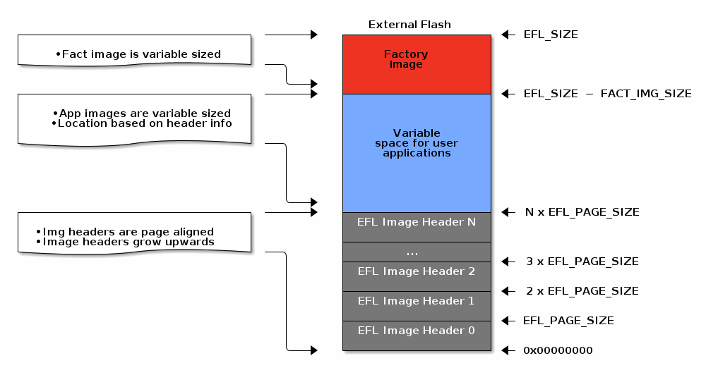
Off-Chip OAD Image External#
The size of the image header table is scalable and can be changed in the user application implementation of the OAD protocol.
Each entry to the image header table contains a pointer to its associated image location in external flash as shown below.
Warning
The convention is that image header sector 0 is reserved for the factory image. This region should be reserved for known good images as the BIM will revert to the factory image if there are no acceptable images in internal or external flash (user section).
OAD Protocol/ Zigbee OTA Cluster#
Currently we have covered all the necessary building blocks for updating an image local to the target device. The only missing piece is a vehicle for sending the OAD blocks over the air and storing them on the target device.
This functionality is implemented by the Zigbee OTA cluster and application. At a high level, they are responsible for:
Determining if the candidate image should be accepted for download
Receiving and unpacking image blocks and storing them
Writing the received blocks to non volatile storage
Verifying the received image post download
The Z-Stack OTA application is implemented in the ota_client.c file and its
associated flash wrappers. The Zigbee OTA cluster is located in the zcl_ota.c
file from the Common ZCL folder.
Task 1 – Setting up the OAD Environment#
The OAD environment requires a two-step setup:
Flash the OTA Server with
zc_ota_serverand connecting it withOtaServer.Flash the OAD Target with the BIM image and the application image. This example will use the
zc_sw_ota_client_offchipproject. For on-Chip OAD projects, a different BIM image will need to be flashed onto the OTA Client.
OAD Server Setup#
The OAD Server is the device responsible for fragmenting an OAD enabled image into chunks of OAD blocks and sending each block over to the OAD Client device as they are requested.
In the case of Z-Stack, the OAD Server is a combination of the OtaServer tool
running on the PC connected to zc_ota_server running on a CC13xx or CC26xx
LaunchPad. zc_ota_server is a Z-Stack enabled network processor application.
OtaServer is a PC tool that is capable of interfacing to zc_ota_server and
performing OAD updates. For more information, refer to the zc_ota_server
README file or the Z-Stack User’s Guide.
Flashing the zc_ota_server Image#
See below for the steps to setup the zc_ota_server image on a CC13xx or CC26xx LaunchPad.
Import the
zc_ota_serverproject within the Z-Stack projects folder into CCS:<SDK_INSTALL_DIR>\examples\rtos\<BOARD_NAME>\zstack\zc_ota_server\tirtos7Build the default project without any modifications
Flash the generated hexfile (located in the default output folder generated during the build) using CCS or UNIFLASH. See image below:
Note
It is best to first Erase Entire Flash from the Settings & Utilities to clear any non-volatile memory before programming the Flash Image
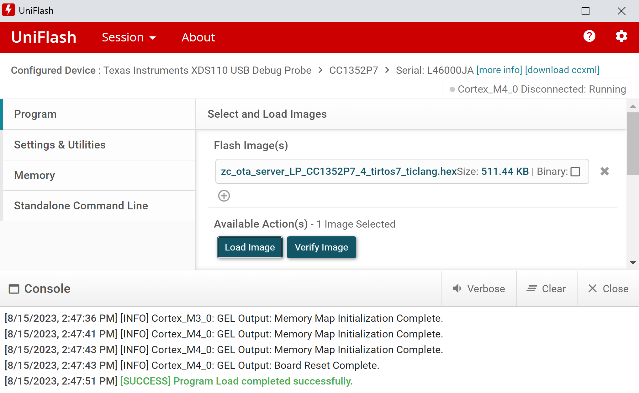
Flashing host_test with UNIFLASH#
Warning
You need to reset the OTA Server application by pressing the RESET button on your Launchpad (button by the micro-USB connector) before you can open the COM port in OtaServer.
Connecting OtaServer to zc_ota_server#
OtaServer and zc_ota_server communicate via USB through the XDS110 UART back channel. See below for a diagram:
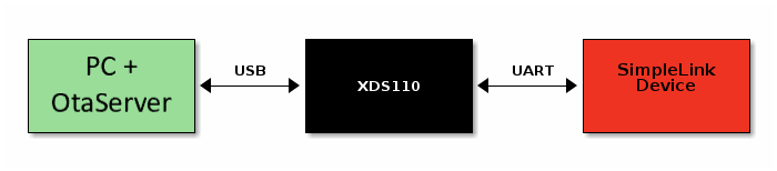
OAD Toolchain#
Find the port used by the UART backchannel of the CC13xx or CC26xx LaunchPad running zc_ota_server. This is the one with the name XDS110 Class Application/User UART.
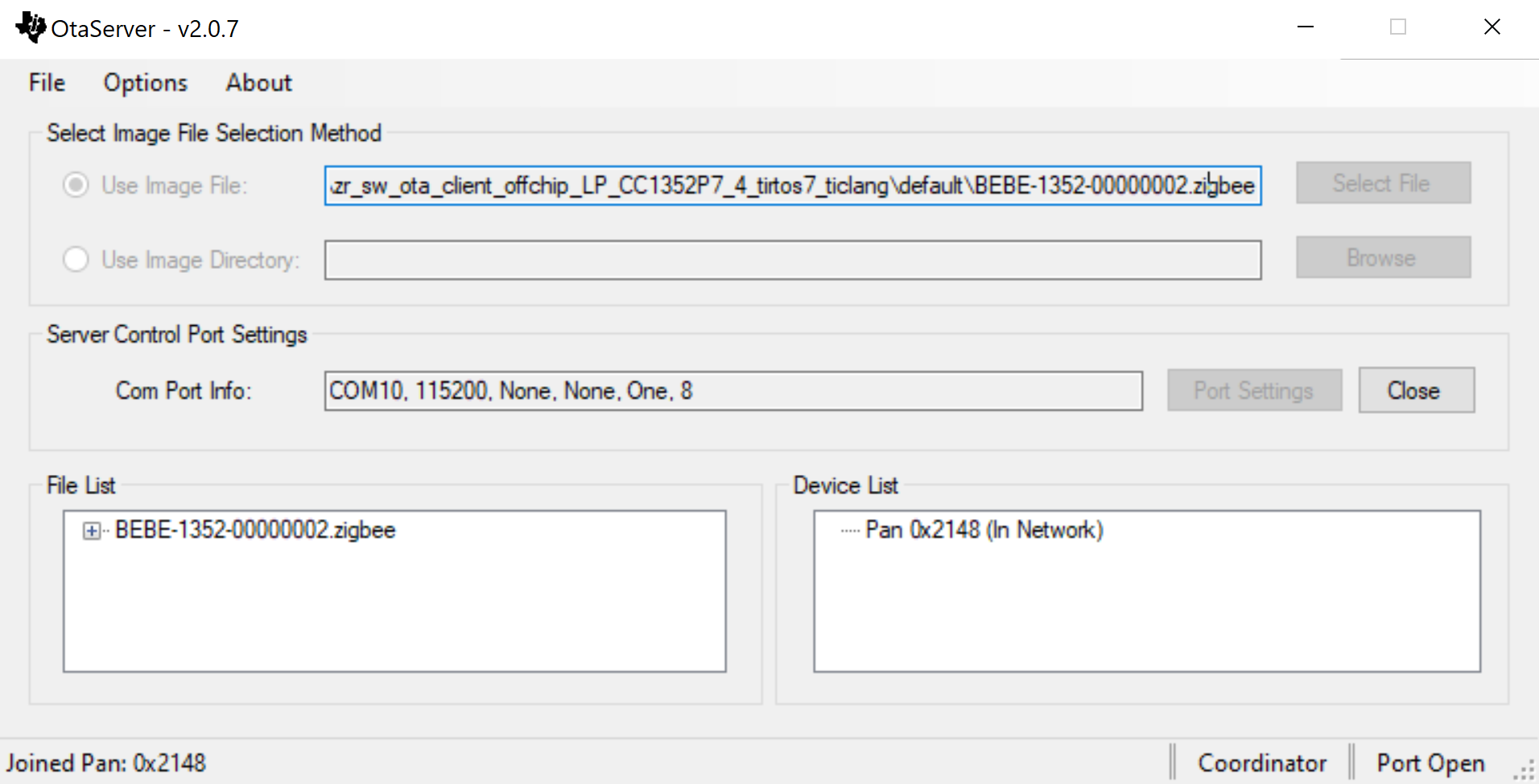
Open OtaServer (see the OtaServer executable in the tools folder of the Z-Stack).
Select the Zigbee OTA Update image file (built by the
zc_sw_ota_client*project)Use the following serial port settings, then select OK.
Port:
<PORT_FROM_ABOVE_STEP>Other settings: 115200, None, None, One, 8
Click Open to initialize the zc_ota_server device.
Press BTN-1 to open the network for joining, at which point the network’s Pan ID will appear in the Device List. Entries within the Pan ID will increase as devices join the network.
A screen shot of a properly initialized OtaServer session is shown below
OtaServer Init Success#
Note
If the Pan ID shows as 0xFFFF after commissioning, Factory Reset the image by holding down BTN-2 while resetting the device, then try to form a network again with BTN-1.
OTA Client Setup#
As we learned in the section Anatomy of an OAD, the target device requires two images (BIM and Zigbee application) to be flashed.
Use a second LaunchPad for the following steps and do not flash the zc_ota_server
board again.
The first image is the BIM. In this lab we will be using the Dual Image Build Configuration.
Import the
bim_onchipproject into CCS:<SDK_INSTALL_DIR>\examples\nortos\<BOARD_NAME>\bim\bim_onchipGo to Project → Build Configurations → Set Active and select Dual_image
Open Application →
bim_onchip_main.cand replace the Dual-image constants code block with the code block below:bim_onchip_main.c#/* Customer to update these as per their images */ #ifdef BIM_DUAL_ONCHIP_IMAGE #define IMAGE_1_HDR_START_PAGE_NUM (0) #define IMAGE_2_HDR_START_PAGE_NUM (42) #if(IMAGE_2_HDR_START_PAGE_NUM <= IMAGE_1_HDR_START_PAGE_NUM) #error "Error: Ensure Image 2 Header starts at a higher flash page as compared to Image 1 Header!" #endif /* Customer to update these as per their images */ /* In the current example:*/ /* Flash pages 0 to 41 is slot 1 */ /* Flash pages 42 to 83 is slot 2 */ /* Flash pages 85 & 86 are being used as shared NV between both the images */ /* Flash page 87 is BIM + CCFG */ /* Total flash pages on CC26x2, CC13x2 is 44 pages */ #define IMAGE_1_START_FLASH_PAGE_NUM (IMAGE_1_HDR_START_PAGE_NUM) #define IMAGE_1_END_FLASH_PAGE_NUM (41) #define IMAGE_2_START_FLASH_PAGE_NUM (IMAGE_2_HDR_START_PAGE_NUM) #define IMAGE_2_END_FLASH_PAGE_NUM (83) #if(IMAGE_2_START_FLASH_PAGE_NUM <= IMAGE_1_START_FLASH_PAGE_NUM) #error "Error: Ensure Image 2 starts at a higher flash page as compared to Image 1!" #endif #if(IMAGE_1_END_FLASH_PAGE_NUM <= IMAGE_1_START_FLASH_PAGE_NUM) #error "Error: Incorrect image 1: end flash page number is less than start flash page number!" #endif #if(IMAGE_2_END_FLASH_PAGE_NUM <= IMAGE_2_START_FLASH_PAGE_NUM) #error "Error: Incorrect image 2: end flash page number is less than start flash page number!" #endif #if(IMAGE_2_END_FLASH_PAGE_NUM <= IMAGE_1_END_FLASH_PAGE_NUM) #error "Error: Ensure Image 2 ends at a higher flash page as compared to Image 1!" #endif #if(IMAGE_2_END_FLASH_PAGE_NUM > 86) #error "Error: CC13x2x7/26x2x7 devices have only 88 flash pages & 87th flash page is reserved for BIM + CCFG !" #endif
Build the project
The user applications cannot be directly flashed as a .hex file as image header
data is required for the BIM to accept the image after startup. Instead we will
be using the generated image *_oad.bin. This is automatically generated in CCS
as a post-build step that runs the OAD Image Tool. This applies to OAD
enabled projects that have SECURITY defined, which is the default setting for
OAD projects in the SDK. This example uses the zr_sw_ota_client_onchip project.
Import the
zr_sw_ota_client_onchipproject within the Z-Stack projects folder into CCS:<SDK_INSTALL_DIR>\examples\rtos\<BOARD_NAME>\zstack\zr_sw_ota_client_onchip\tirtos7Build the default project without any modifications
Flash the generated
bim_onchip_*.hex(from the Dual_image output folder of the BIM project) andzr_sw_ota_client_onchip_*_oad.bin(located in the default output folder generated during application build) using UNIFLASH. See image below:
Note
It is best to first Erase Entire Flash from the Settings & Utilities to clear any non-volatile memory before programming the Flash Images
Flashing Off-Chip BIM and application image#
The first image is the BIM. In this lab we will be using the Dual Image Build Configuration.
Import the
bim_offchipproject into CCS:<SDK_INSTALL_DIR>\examples\nortos\<BOARD_NAME>\bim\bim_offchipBuild the default project without any modifications
The user applications cannot be directly flashed as a .hex file as image header
data is required for the BIM to accept the image after startup. Instead we will
be using the generated image *_oad.bin. This is automatically generated in CCS
as a post-build step that runs the OAD Image Tool. This example uses the
zr_sw_ota_client_offchip project.
Import the
zr_sw_ota_client_offchipproject within the Z-Stack projects folder into CCS:<SDK_INSTALL_DIR>\examples\rtos\<BOARD_NAME>\zstack\zr_sw_ota_client_offchip\tirtos7Build the default project without any modifications
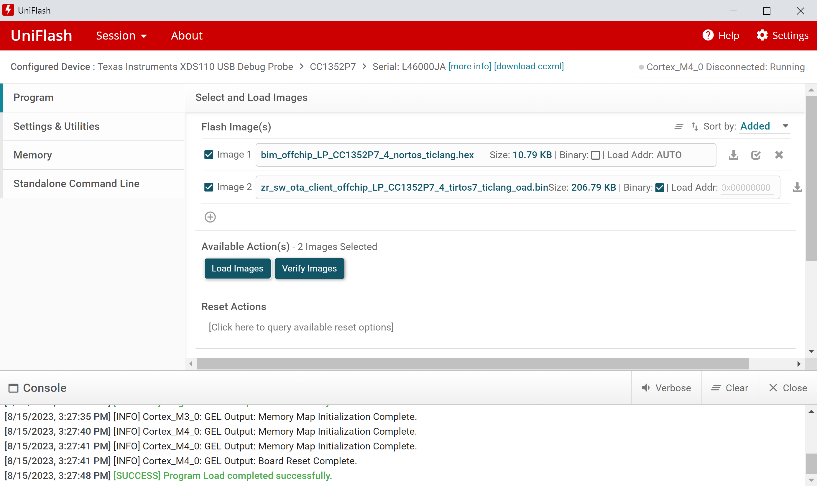
Flash the generated
bim_offchip_*.hex(from the Dual_image output folder of the BIM project) andzr_sw_ota_client_offchip_*_oad.bin(located in the default output folder generated during application build) using UNIFLASH. See image below:
Note
It is best to first Erase Entire Flash from the Settings & Utilities to clear any non-volatile memory before programming the Flash Images
Flashing Off-Chip BIM and application image#
Warning
Once the OTA Client is set up, a reset is required to start the BIM and have it load the application image. You can reset the target by pressing the RESET button on your Launchpad (button by the micro-USB connector). At this point, you should see the application menu on a serial terminal.
Task 2 – Running the OAD Demo#
Now that the OAD environment is ready, we will download a new image over Zigbee using OtaServer.
Modifying the Image Version#
Modifying the application image version is a quick and easy way to verify that the OAD has completed. Some sample apps will display their image version in the terminal window.
Within the existingzr_sw_ota_client_onchip project:
Open the file
zr_sw_ota_client_onchip.syscfginside of the SysConfig Editor. Navigate to the NVS module and swap the region bases of CONFIG_NVSINTERNAL1 and CONFIG_NVSINTERNAL2Navigate to Project Properties → CCS Build → ARM Linker → Advanced Options → Command File Preprocessing and define
OAD_IMG_A=1Go to Project Properties → CCS Build → ARM Compiler → Predefined Symbols and modify
OTA_APP_VERSION=0x00000002Change the Project Properties → CCS Build → Steps → Post-build steps to use
00000002on the last lineRebuild the application project and generate a new
.zigbeeOTA file.
Note
Steps 1 and 2 must be returned to their default settings for the next OTA update given the Dual image configuration, and then continue this process for the lifetime of the device. Steps 3 and 4 values also must be incremented for every OAD update request so that the application knows that a new version is available from the OtaServer.
Within the existingzr_sw_ota_client_offchip project:
Go to Project Properties → CCS Build → ARM Compiler → Predefined Symbols and modify
OTA_APP_VERSION=0x00000002Change the Project Properties → CCS Build → Steps → Post-build steps to use
00000002on the last lineRebuild the application project and generate a new
.zigbeeOTA file.
Note
Steps 1 and 2 values must be incremented for every OAD update request so that the application knows that a new version is available from the OtaServer.
OAD using OtaServer#
Now switch back to the OtaServer to perform an OAD with the new version of our application.
Make sure the OTA Server Zigbee network is open for joining by pressing down BTN-1 on the respective LaunchPad.
Connect the OAD Client device either by pressing its BTN-1 or by using the “COMMISSION” UI option (connected through a terminal program using the respective XDS110 Class Application/User UART and 115200 baud rate connection).
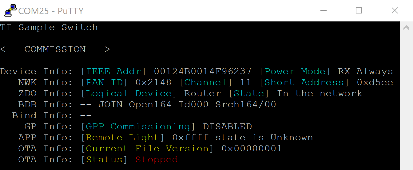
Image V1 running#
Once connected, wait for the OTA process to begin. The OTA client must first recognize the OTA server and query for a new image before it can begin requesting OAD update block messages.
Users will be aware from either the OtaServer or OTA client terminal that the process has begun, indicated with status bars. This will typically take between 5 to 10 minutes to complete.
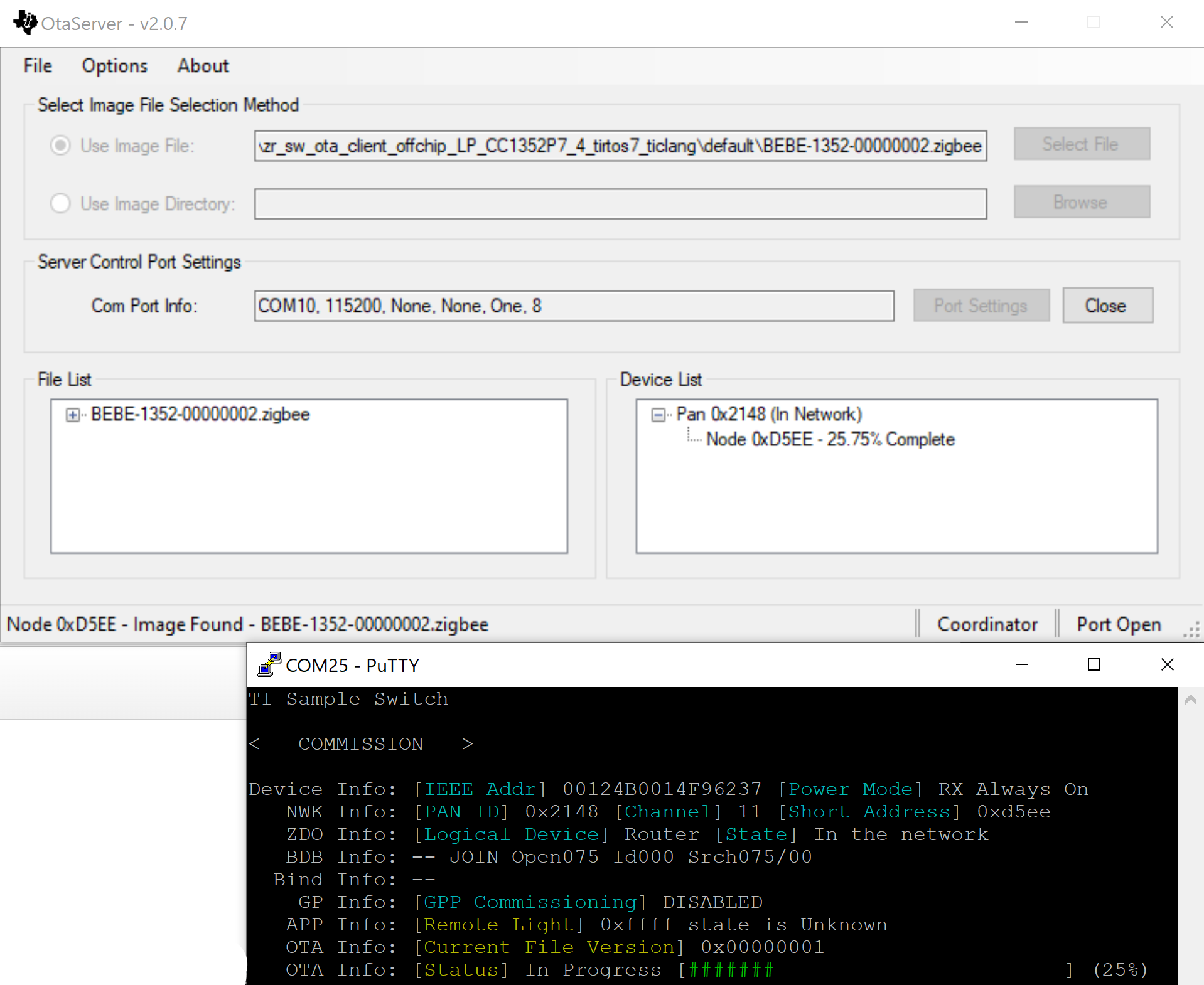
OTA upgrade in progress#
Note
Want the OTA process to go faster? Try increasing the
OTA_MAX_MTUfrom withinCommon/zcl/zcl_ota.hError
Did the OTA upgrade fail during the update process? No worries, as the OTA client will recognize the failure and has maintained the original application image so that it can continue operation as expected and then re-start the upgrade attempt when available
Once the OAD process is completed a delay of several seconds is expected before the new application image is verified, at which point the application will change the OAD header image flag status before resetting the device so that the BIM recognizes the new application image and loads it accordingly.
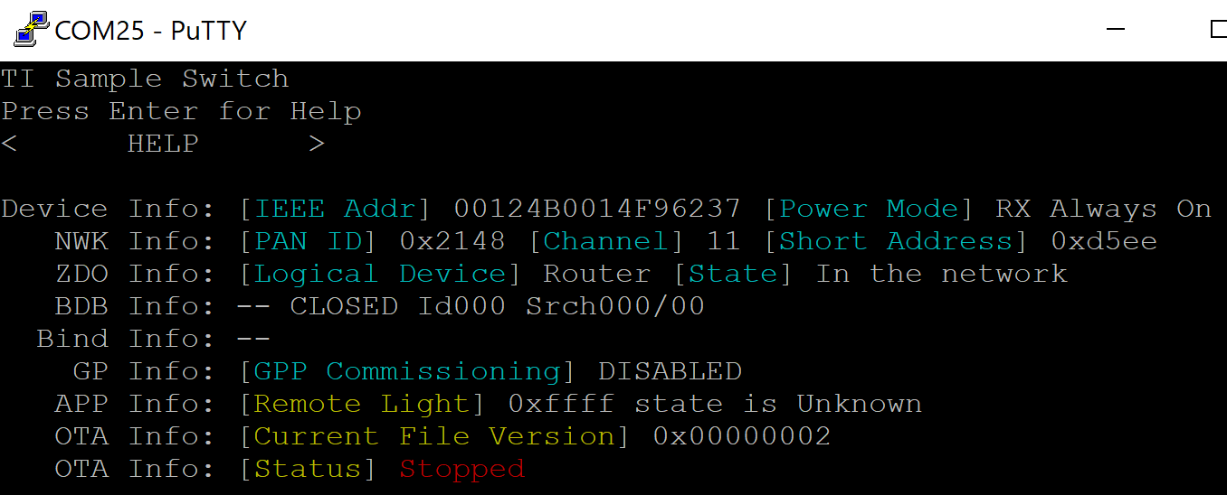
Image updated to V2#
The OTA client node will rejoin the existing Zigbee network without any further action from the user. Now that the new image it running, the OtaServer update image file will be consistent with the same image version. Therefore a new OTA update will not proceed given that Options -> Version Check Image File is not selected. Congratulations, the OTA process is now completed! Keep in mind that the Image version modification must be performed for each following OTA image candidate.