|
F29x Motor Control SDK
1.00.00.00
|


|
|
F29x Motor Control SDK
1.00.00.00
|
|
← Back to Reference Designs Overview
Automotive, High-Power, High-Performance SiC Traction Inverter Reference Design
| TIDM-02014 Design Specification | ||
|---|---|---|
| Parameters | Specifications | Notes |
| P_out | 300kW | Rated output power |
| V_dc | 800V | Recommended DC bus voltage |
| I_dc | 300A | Rated DC bus current |
| F_SWmax | 60kHz | Maximum allowable switching frequency |
TIDM-02014 is a 800-V, 300kW SiC-based traction inverter system reference design developed by Texas Instruments and Wolfspeed provides a foundation for OEMs and design engineers to create high-performance, high-efficiency traction inverter systems and get to market faster. This solution demonstrates how the traction inverter system technology from TI and Wolfspeed improves system efficiency by reducing the overshoot in available voltages with a high-performance isolated gate driver and real-time variable gate drive strength driving the Wolfspeed SiC power module. The isolated gate driver coupled with TI’s isolated bias supply solution significantly reduces the PCB size providing more than 2X smaller PCB area, less than 4mm height and eliminating 30+ discrete components improving system power density. TI’s high-control performance MCUs featuring tightly-integrated, innovative real-time peripherals enable effective traction motor control even at speeds greater than 20,000 RPM. Fast current loop implementation helps minimize motor torque ripple and provides smooth speed-torque profiles. The mechanical and thermal design of the system is provided by Wolfspeed.
| Software Device Usage | ||
|---|---|---|
| Device | F29H85x (200MHz) | |
| CPU | C29x CPU1 | |
| Memory Consumption | O1 - RAM: 23KB Flash: 144KB O3 - RAM: 23KB Flash: 109KB | |
| Performance | 20% CPU1 utilization | |
| # of PWM Channels | 8 EPWM Channel (6 powerstage + 1 resolver excitation trigger + 1 SDFM trigger) | |
| # of ADC Channels | 6 ADC Channel | |
| # of SDFM Channels | 1 SDFM Channel | |
| Control Methodology | one PI speed control loop, one PI current control loop, one PI torque control loop | |
| ISR Frequency | FOC_ISR: 40kHz | |
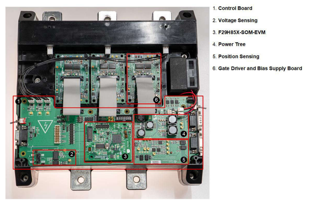
TIDM-02014 Board Overview | 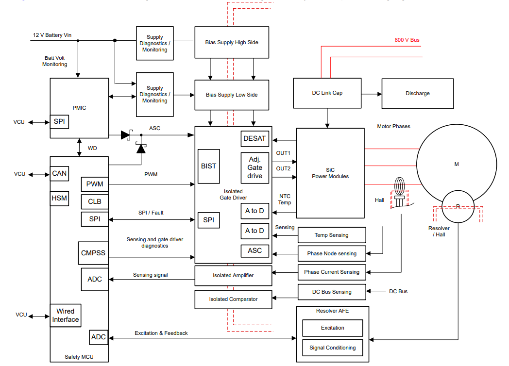
TIDM-02014 Block Diagram |
Useful links regarding the reference design are provided below:
Quick guide to run the example in different modes mentioned below:
| Parameter values in different control modes | ||
|---|---|---|
| Control Modes | Parameter values | |
| Voltage control mode | posFdbk: 0 speedRef: 0.02 VqTesting: 2 runMotor: 4 | |
| Current control mode | posFdbk: 1 | |
| Speed control mode | posFdbk: 1 | |
Shown below lists all the software revision history for this reference design:
| Software Revision | In SDK Release | Changelog |
|---|---|---|
| v1.00.00 | 1.00.00.00 | First release, on F289H85x devices in F29x Motor Control SDK |
For EVM design files such as schematics, BOM, PCB layouts & assembly files, please visit TI design webpage from the link above.
For additional help and support, please visit E2E™ design support forum ![]()
 1.8.17