3.10. Multimedia Guide
3.10.1. Introduction
AM62Ax family of processors have the following hardware accelerators:
- VPU (Video Processing Unit):
VPU/Video Accelerator is a 4K codec that supports both HEVC and H.264/AVC video formats. It provides high performance encode and decode capability up to 8bit 4K@60fps with a single-core architecture.
- VPAC (Vision Pre-processing Accelerator):
VPAC subsystem is a set of common vision primitive functions, performing pixel data procesing tasks, such as: color processing and enhancement, noise filtering, wide dynamic range (WDR) processing, lens distortion correction (LDC), pixel remap for de-warping, on-the-fly scale generation, on-the-fly pyramid generation.
This Multimedia guide will cover the following topics:
VPU software Architecure, Encode/Decode capabilities, Demos.
VPAC Architecture, Data flows using OpenVX GStreamer plugins.
3.10.2. VPU - Multimedia Video Accelerator
The Codec IP is a stateful encoder/decoder. It is found on the AM62Ax SoC. Combined H.264 and H.265 encoder/decoder used in the Texas Instruments AM62Ax SoC.
- Hardware capabilities :
Maximum resolution: 8192x8192 It can handle this resolution, but not necessarily in real-time.
Minimum resolution: 256x128
- Constraints :
A picture width shall be multiple of 8.
A picture height shall be multiple of 8.
- Multiple concurrent encode/decode streams :
Number of concurrent streams dependant on resolution and framerate.
- Encoder :
Capable of encoding H.265 Main and Main Still Picture Profile @ L5.1 High tier.
Capable of encoding H.264 Baseline/Constrained Baseline/Main/High Profiles Level @ L5.2.
- Decoder :
Capable of decoding H.265 Main and Main Still Picture Profile @ L5.1 High tier.
Capable of decoding H.264 Baseline/Constrained Baseline/Main/High Profiles @ L5.2.
3.10.2.1. Software Architecture Overview
V4L2(Video for Linux API version 2) driver for codec device performs decode/encode operation by controlling VPU(Video Processing Unit). V4L2 is one of the media frameworks widely used in Linux system and supports various media devices such as webcam, image sensor, VBI output, radio,and codec. Device vendors offer V4L2 framework compliant driver for the device so that application programmer can control a wide range of devices with the same interface through using ioctl().
3.10.2.2. Software Architecture
As show in the figure below, the VPU V4L2 driver is in the kernel space. It communicates with host application through IOCTL interface and communicates with VPU through the predefined host interface registers. Host application sends IOCTL command, which is delivered via the V4L2 kernel module on V4L2 framework.
VPU V4L2 driver consists of three main components: VPU, VPU_DEC, and VPU_ENC. VPU is involved in tasks without dependency on decoding/encoding such as Handle interrupt, Load firmware, and Register V4L2 device. VPU_DEC performs decode and related tasks: Communicate with V4L2 IOCTL, Decode video with VPU API, Register video device VPU_ENC performs encode and related tasks: encoding Communicate with V4L2 IOCTL, Encode video with VPU API, Register video device.

3.10.2.3. GStreamer Plugins for Multimedia
Open Source GStreamer Overview
GStreamer is an open source framework that simplifies the development of multimedia applications, such as media players and capture encoders. It encapsulates existing multimedia software components, such as codecs, filters, and platform-specific I/O operations, by using a standard interface and providing a uniform framework across applications.
The modular nature of GStreamer facilitates the addition of new functionality, transparent inclusion of component advancements and allows for flexibility in application development and testing. Processing nodes are implemented via GStreamer plugins with several sink and/or source pads. Many plugins are running as ARM software implementations, but for more complex SoCs, certain functions are better executed on hardware-accelerated IPs like wave5 (DECODER and ENCODER).
GStreamer is a multimedia framework based on data flow paradigm. It allows easy plugin registration just by deploying new shared objects to the /usr/lib/gstreamer-1.0 folder. The shared libraries in this folder are scanned for reserved data structures identifying capabilities of individual plugins. Individual processing nodes can be interconnected as a pipeline at run-time, creating complex topologies. Node interfacing compatibility is verified at that time - before the pipeline is started.
GStreamer brings a lot of value-added features to AM62Ax SDK, including audio encoding/decoding, audio/video synchronization, and interaction with a wide variety of open source plugins (muxers, demuxers, codecs, and filters). New GStreamer features are continuously being added, and the core libraries are actively supported by participants in the GStreamer community. Additional information about the GStreamer framework is available on the GStreamer project site: http://gstreamer.freedesktop.org/.
Hardware-Accelerated GStreamer Plugins
One benefit of using GStreamer as a multimedia framework is that the core libraries already build and run on ARM Linux. Only a GStreamer plugin is required to enable additional hardware features on TI’s embedded processors with both ARM and hardware accelerators for multimedia. The open source GStreamer plugins provide elements for GStreamer pipelines that enable the use of hardware-accelerated video decoding through the V4L2 GStreamer plugin.
Below is a list of GStreamer plugins that utilize the hardware-accelerated video decoding/encoding in the AM62Ax.
Encoder
v4l2h264enc and v4l2h265enc
Decoder
v4l2h264dec and v4l2h265dec
3.10.2.4. Demos
Encoder
- H.264/AVC:
gst-launch-1.0 filesrc location=./avc_enc_input_416x240.yuv ! rawvideoparse width=416 height=240 format=i420 ! v4l2h264enc ! filesink location=./avc_enc_output_416x240.bin
- H.265/HEVC:
gst-launch-1.0 filesrc location=./hevc_enc_input_416x240.yuv ! rawvideoparse width=416 height=240 format=i420 ! v4l2h265enc ! filesink location=./hevc_enc_output_416x240.bin
Decoder
- H.265/HEVC:
gst-launch-1.0 filesrc location=./hevc_dec_input.265 ! h265parse ! v4l2h265dec ! filesink location=./hevc_dec_output.yuv
- H.264/AVC:
gst-launch-1.0 filesrc location=./avc_dec_input.264 ! h264parse ! v4l2h264dec ! filesink location=./avc_dec_output.yuv
3.10.3. VPAC - Vision Pre-processing Accelerator
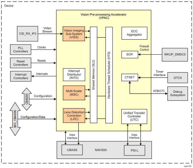
The Vision Pre-processing Accelerator (VPAC) subsystem is a set of common vision primitive functions, performing pixel data processing tasks, such as: color processing and enhancement, noise filtering, wide dynamic range (WDR) processing, lens distortion correction, pixel remap for de-warping, on-the-fly scale generation, on-the-fly pyramid generation. The VPAC offloads these common tasks from the main SoC processors (ARM, DSP, etc.), so these CPUs can be utilized for differentiated high-lelvel algorithms. The VPAC is designed to support multiple cameras by working in time-multiplexing mode. The VPAC works as a front end to vision processing pipeline and provides for further processing by other vision accelerators or processor cores inside the SoC. The VPAC also includes an imaging pipe, which can be integrated on-the-fly with external camera sensor, as well as does memory-to-memory (M2M) processing on pixel data.

3.10.3.1. Block Diagram Overview
The VPAC subsystem includes imaging pipe to do image processing on raw pixels (bayer, RCCC, etc.). The VPAC subsystem loads pixel data either from memory (for example, DDR or on-chip memory), or captured from camera sensor (via external module on SoC level), and applies many vision primitive functions such as image processing, scaling to generate image pyramids, noise filtering, correcting lens distortion, applying perpective transformation for stereo rectification, etc. Optionally, the VPAC subsystem can also do dynamic range management on received image data. The output image processed data generated by the VPAC subsystem is written into memory (for example, DDR or on-chip). The VPAC subsysem supports software managed and HTS controlled flexible load/store of data using K3 DMA infrastructure sub-modules.
The VPAC subsystem includes the following image processing harware accelerators (HWAs) and infrastructure blocks.
- Vision Imaging Subsystem (VISS) :
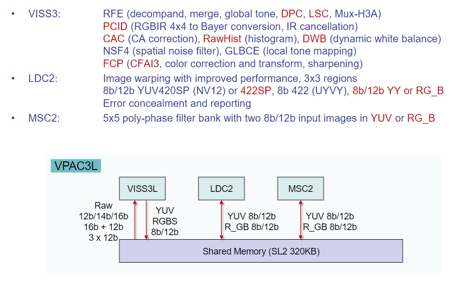
The VISS does on-the-fly (OTF) processing on raw pixels captured from camera sensor. It also does memory to memory processing for data captured from other sources to its parallel port or video port. The VISS uses VPAC infrastructure modules (HTS, DRU/UTC, interrupt aggregator, etc.) for flow and data management. The VISS consists of following Hardware Accelerators (HWA).
RAW Front End (RFE) block
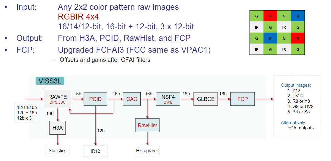
The RFE block does RAW pixel (that is, Bayer, RCCC, RGBW, etc.) processing on captured image data from sensor. The processed data is later passed on to the NSF4V block, or otherwise it is passed onto the Flexible Color Proccesing (FCP) block for demosaicing and color conversion. The RFE includes also the H3A block, which supports the control loops for auto focus (AF), auto white balance (AWB) and auto exposure (AE) by computing image statistics.
Global Local Brightness Contrast Enhancement (GLBCE) module
The GLBCE module is used for dynamic range control within image for visual quality. If a contrast enhancement on the input image is required for visual quality, the RFE output is processed by the NSF4v and GLBCE blocks and then passed onto the FCP block. Otherwise, if contrast enhancement is not required, the NSF4v and GLBCE blocks can be bypassed, and the RFE output is directly provided to the FCP block.
Flexible Color Processing (FCP) block
The FCP block receives data from GLBCE and does demosaicing and color conversion. The output of the color processing is sent to the internal EE (Edge Enhancer) block, if it is enabled, before being ouput to VPAC shared memory. Otherwise, the FCP output data is directly sent to VPAC shared memory to be written into external memory for further vision processing by programmable processors (that is, DSP or Arm), or other vision hardware accelerators at SoC level.
Load/Store Engine (LSE)
- The LSE is an infrastructure block, which provides the following functions:
Receives data, captured through MIPI CSI-2 image sensor (by external module at SoC level), for on-the-fly image processing to reduce DDR bandwidth and latency. LSE also provides horizontal and vertical blanking cycles to allow core data path to settle at proper boundary of line and frame.
Provides access to VPAC SL2 memory for loading/storing data. Loaded data from SL2 are passed on to unpacker function of LSE for RFE. Packed data after FCP/H3A processing is written into SL2.
Pixel packing/unpacking. Source data (512-bit) for RFE processing is loaded from SL2 and passed onto unpacker function for pixel extraction. Extracted pixels are driven on the video port of RFE. Similarly, FCP produced pixels are driven to packer function for eventual write into SL2. H3A generated data is pseudo mapped as pixel of 32 bits for packing purpose and directly driven by RFE.
Event control. HTS events are generated at line level. These events are routed to RFE to start the processing. For each consumed line HTS needs task done indication. For some initial lines consumed, there would not be any valid data output. Similarly, H3A generated data will be at paxel/window height number of lines. For consumed lines, which is not producing any valid data to be written into DDR, HTS needs to be indicated with separate mask bits for each output streams. For initial lines, when there is no valid output due to delay lines, LSE will still generates mask output to HTS indicating lack of proper output data.

- Lens Distortion Correction (LDC) module :
The LDC module deals with lens geometric distortion issues in the camera system. The distortion can be common optical distortions, such as barrel distortion, pincushion distortion, or fisheye distortion. Correction is not limited to just these types of distortions. The LDC module consists of a Back Mapping block (which gives coordinates of the distorted image as a function of coordinates of the undistorted output image), a delta_x/delta_y offset table, frame buffer inetrface, buffer, an interpolation block, and SL2 interface. The frame buffer is external to the LDC module, and is usually in an off-chip SDRAM. The LDC module uses the common VPAC infratructure modules (HTS, DRU/UTC, interrupt aggregator, etc.) for flow and data management, except for loading input data for which it has its own DMA engine.
- Multi-Scaler (MSC) module :
The MSC consists of 10 programmable resizers performing multi-thread/multiscaling operations (2-input to N-outputs, and 2-input to M-outputs, where N+M is 10 or less). Each processing thread of MSC reads its input plane data from the SL2 circular line buffer, performs multi-scaling operations (ratios between X and 0.25X) on the same input, and writes out results to SL2 circular line buffers. In case of on-the-fly operation, the source data is generated from another VPAC HWA. In case of memory-to-memory operation, the source data is read from the external memory. Data transfers from/to SL2 to/from external memory (or another HWA) are handled by the VPAC DMA controller (DRU/UTC), with transfer request events coming from the VPAC HTS module. The MSC module uses the VPAC infrastrucutre modules (HTS, DRU/UTC, interrupt aggregator, etc.) for flow and data management.
- Noise-filter (NF):
The NF module reads data from memory (that is, DDR or on-chip) to the shared memory (SL2) and does bilateral filtering to remove noise. The output of the NF block can be sent to external memory (that is, DDR) from the shared memory (SL2) or can be further re-sized using the MSC module. The NF module supports two modes of filtering: bilateral filtering mode (where the overall weights are 8-bit unsigned weights computed based on center pixels), and generic filtering mode (where all weights are 9-bit signed value read LUT). The NF module uses the VPAC infrastrucutre modules (HTS, DRU/UTC, interrupt aggregator, etc.) for flow and data management.
- Hardware Thread Scheduler (HTS):
The HTS module is a messaging layer for low-overhead synchronization of the parallel computing tasks and DMA transfers, and is independent from the host processor. It allows autonomous frame level processing for the VPAC subsystem. The HTS module defines various aspects of synchronization and data sharing between the VPAC HWAs. With regards to producer and consumer dependencies, the HTS module ensures that a task starts only when input data and adequate space to write out data is available. In addition to this, it also takes care of pipe-up, debug, abort and interrupt management aspects related to the VPAC HWAs.
- Common shared level 2 (SL2) memory:
The SL2 memory subsystem implements a full crossbar inteconnect, and serves as input/output scratch memory for the VPAC HWAs.
- Data Router Unit (DRU):
The DRUs acts like (and is also referred to as) a Universal Transfer Controllers(UTCs) for managing real-time and nonreal-time DMA transfers.
- Switched Central Resource (SCR) block:
The SCR acts like a 256-bit data routing interconnect within the VPAC subsystem, and is used to route UTC traffic onto SL2 memory or for external (system level) access.
- Counter, Timer and System Event Trace (CTSET) module:
The CTSET module provides event tracing capabilities for debug purposes.
- ECC Aggregator:
The ECC Aggregator modules provide a mechanism to control and monitor certain internal ECC RAMs via Single Error Correction (SEC) and Double Error Detection (DED) functions.

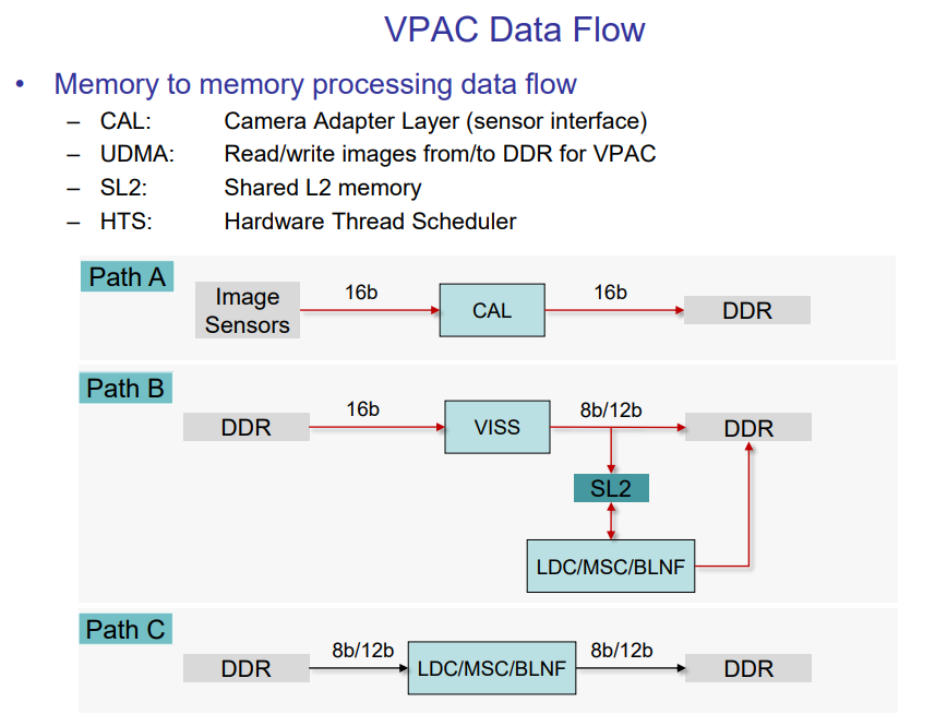
3.10.3.2. Data Flow

