### Introduction
The SDK includes drivers for a number of peripherals. These drivers are provided in the `<SDK_INSTALL_DIR>/source/drivers` directory. The driver examples show how to use these drivers.
In this tutorial we are going to show how to add a driver to an MCU+ SDK application. We will be using the NoRTOS Empty example project for the R5F core as the starting point and will be adding the GPIO and LED drivers to toggle an LED.
<hr>
<br>
### Step 1: Import the Empty Example Project
First, let's import the Empty example project to use as the starting point.
<br>
<hr>
#### a. In CCS, go to *View → Resource Explorer* to open Resource Explorer
<hr style="width:50%; margin: auto;" />
#### b. Go to *MCU+ SDK for AM243x → Examples → {Board} → empty → r5fss0-0_nortos → empty*
<hr style="width:50%; margin: auto;" />
#### c. Click the **Import** icon at the top-right to import the project to CCS
<br>
<center>  </center>
<hr>
<br>
### Step 2: Add a GPIO Instance
To use the GPIO driver, we need to add an instance.
<br>
<hr>
#### a. Double-click **`example.syscfg`** to open the SysConfig GUI
<br>
<br>
<hr style="width:50%; margin: auto;" />
#### b. Click on **GPIO** and click **ADD** to add a GPIO instance
<br>
<br>
<hr style="width:50%; margin: auto;" />
#### c. Enter a **Name**. Set **PIN Direction** to **Output** since we want to drive an LED
For this example, we are using the name "USER_LED_2"
<br>
<br>
<hr style="width:50%; margin: auto;" />
#### d. Check **Use MCU Domain Peripherals** and select the **MCU_GPIO0** GPIO Peripheral
<br>
<br/>
<hr style="width:50%; margin: auto;" />
#### e. Select the pin tied to the LED we want to blink. For this example, we are using pin A7 tied to GPIO User LED 2.
SysConfig will automatically configure the PinMux for the selected pin.
<br>
<hr>
<br>
### Step 3: Add an LED Instance
To use the LED driver, we need to add an instance.
<br>
<hr>
#### a. Similarly, click on **LED** and click **ADD** to add an LED instance
<hr style="width:50%; margin: auto;" />
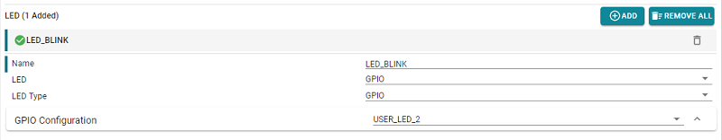
#### b. Provide a **Name** to be used by the application (or leave it as the default).
For this example we use "LED_BLINK"
<hr style="width:50%; margin: auto;" />
#### c. Set the **LED** and **LED Type** to **GPIO**
<hr style="width:50%; margin: auto;" />
#### d. Select the previously created GPIO Configuration: **USER_LED_2**
<br>
<hr>
<br>
### Step 4: Link the Required Libraries
To use the driver APIs, we need to link the required libraries.
<br>
<hr>
#### a. Select your project and go to *Project > Show Build Settings...*
<hr style="width:50%; margin: auto;" />
#### b. In the project's build settings, go to *Build > Arm Linker > File Search Path*
<hr style="width:50%; margin: auto;" />
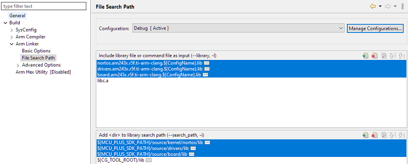
#### c. In the **File Search Path** window, add the required libraries and their respective paths
Note: The Empty example project already has the DPL and Drivers library linked so we just need to add the Board library for this example.
##### Board Library
The board library is needed to use the **LED** module.
* **File:** `board.am243x.r5f.ti-arm-clang.${ConfigName}.lib`
* **Path:** `${MCU_PLUS_SDK_PATH}/source/board/lib`
<br>
##### DPL Library
The DPL library is needed to use the **Clock**, **Debug Log**, and **MPU** modules. Since we are using NoRTOS on R5 for this example, we need to link the following.
* **File:** `nortos.am243x.r5f.ti-arm-clang.${ConfigName}.lib`
* **Path:** `${MCU_PLUS_SDK_PATH}/source/kernel/nortos/lib`
<br>
##### Drivers Library
The Drivers library is needed to use the GPIO driver.
* **File:** `drivers.am243x.r5f.ti-arm-clang.${ConfigName}.lib`
* **Path:** `${MCU_PLUS_SDK_PATH}/source/drivers/lib`
<br>
You should now have the following:
<hr>
<br>
### Step 5: Add the Application Code
The LED Blink application consists of using the `LED_on()`, `LED_off()`, and `ClockP_sleep()` functions.
<br>
<hr>
#### a. Rename `empty.c` to `gpio_led_blink.c` to better represent its function
<hr style="width:50%; margin: auto;" />
#### b. Add the `LED_on()` and `LED_off()` functions to toggle the LED
<br>
The `LED_on()` and `LED_off()` functions require the handle to the LED instance. Handles created by SysConfig follow the syntax `"g<module>Handle[<instance name>]"` in camelCase convention.
So in this case, our LED handle is `gLedHandle[LED_BLINK]` (`LED_BLINK` was the name of the LED instance we created in Step 3b).
```c
int32_t status;
status = LED_on(gLedHandle[LED_BLINK], 0U);
DebugP_assert(SystemP_SUCCESS == status);
status = LED_off(gLedHandle[LED_BLINK], 0U);
DebugP_assert(SystemP_SUCCESS == status);
```
(Optional) Check the return status of `LED_on()` and `LED_off()` and assert an error if it does not return successful.
<hr style="width:50%; margin: auto;" />
#### c. Surround the code in a while() loop and add a loop counter
`uint32_t loopcnt` defines how many times the LED will blink.
```c
int32_t status;
uint32_t loopcnt = 5, delaySec = 1;
while (loopcnt > 0)
{
status = LED_on(gLedHandle[LED_BLINK], 0U);
DebugP_assert(SystemP_SUCCESS == status);
status = LED_off(gLedHandle[LED_BLINK], 0U);
DebugP_assert(SystemP_SUCCESS == status);
loopcnt--;
}
```
<hr style="width:50%; margin: auto;" />
#### d. Add a delay
Add a delay so that the LED blink is visible to the human eye.
```c
int32_t status;
uint32_t loopcnt = 5, delaySec = 1;
DebugP_log("GPIO LED Blink Start \r\n");
while (loopcnt > 0)
{
status = LED_on(gLedHandle[LED_BLINK], 0U);
DebugP_assert(SystemP_SUCCESS == status);
ClockP_sleep(delaySec);
status = LED_off(gLedHandle[LED_BLINK], 0U);
DebugP_assert(SystemP_SUCCESS == status);
ClockP_sleep(delaySec);
loopcnt--;
}
DebugP_log("GPIO LED Blink End \r\n");
```
(Optional) Add print statements to the start and end of the LED blink.
<hr style="width:50%; margin: auto;" />
#### e. **Save** your project and click **Debug** to build and run your application

<br>
<hr>
### []{ } Knowledge Check
<br>
**1.** To use the Clock module, which library needs to be linked?
[quiz]
v DPL --> Correct!
x Board --> Incorrect
x Drivers --> Incorrect
[quiz]
<br>
**2. True or false:** To toggle an LED, the GPIO Pin Direction needs to be set to Output.
[quiz]
v True --> Correct!
x False --> Incorrect
[quiz]
<br>
**3.** To use the LED module, which library needs to be linked?
[quiz]
x DPL --> Incorrect
v Board --> Correct!
x Drivers --> Incorrect
[quiz]
<br>
<hr>
### Next Steps
<br>
Now that you have learned how to add a driver to an MCU+ SDK application, you can progress to the next module in the series where you will learn essentials of the MCU+ SDK Linker Command File.
##### [Part 5: Linker Command File Essentials >](linker_cmd_file.html)
<br>
<hr>
### Additional Reading
<br>
##### MCU+ SDK User Guide: [SOC Peripheral Drivers](https://software-dl.ti.com/mcu-plus-sdk/esd/AM243X/latest/exports/docs/api_guide_am243x/DRIVERS_PAGE.html)
##### MCU+ SDK User Guide: [Board Peripheral Drivers](https://software-dl.ti.com/mcu-plus-sdk/esd/AM243X/latest/exports/docs/api_guide_am243x/BOARD_DRIVERS_PAGE.html)
<br>
<hr>
{{r> [Back to Home](../overview.html)}}
{{r **Was this helpful? Let us know here:** [mcu_plus_academy_feedback@list.ti.com](mailto:mcu_plus_academy_feedback@list.ti.com)}}
<div align="center" style="margin-top: 4em; font-size: smaller;">
<a rel="license" href="https://creativecommons.org/licenses/by-nc-nd/4.0/"><img alt="Creative Commons License"
style="border-width:0" src="..//web_support/cc_license_icon.png" /></a><br />This work is licensed under a <a
rel="license" href="https://creativecommons.org/licenses/by-nc-nd/4.0/">Creative Commons
Attribution-NonCommercial-NoDerivatives 4.0 International License</a>.</div>