# Overview
This guide is intended for users with a TI mmWave sensor evaluation module (EVM).
The guide will walk through setting up the boards into either **Flashing Mode** or **Functional Mode**.
In flashing mode, a program may be loaded onto the device's external flash.
In functional mode, the EVM boots automatically from flash and begins executing
the image stored there.
This guide supports several different EVM's so be sure to follow the steps
that apply to your device.
---
# mmWaveICBoost Initial Configuration
This section is only necessary if the EVM is being attached to an
mmWaveICBoost carrier board and the carrier board has not been configured
for flashing or functional mode previously.
[[+d Expand for steps for inital mmWaveICBoost Configuration
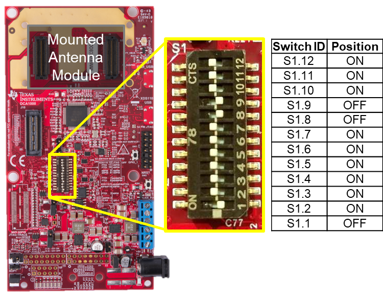
## Set S1 Switches
Set the S1 switch combination as shown in the image below. This puts
the mmWaveICBoost in its standalone operation as opposed to in
development mode for use with a DCA1000.
+]]
---
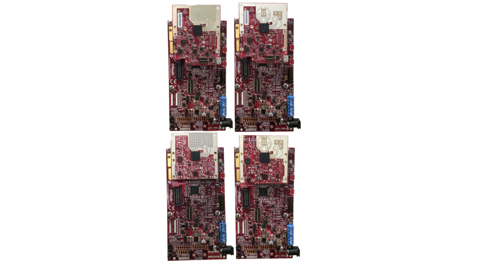
# ISK, ISK-ODS, and L EVM's
This section applies to the following boards:
* [xWR6843ISK](http://www.ti.com/tool/IWR6843ISK)
* [xWR6843ISK-ODS](http://www.ti.com/tool/IWR6843ISK-ODS)
* [xWR6843LEVM](https://www.ti.com/tool/IWR6843LEVM)
## ISK Style Standalone Mode
* This section describes setting an ISK, ISK-ODS, or LEVM to Flashing or
Functional mode when used **without** a mmWaveICBoost carrier board.
* Only ISK Rev C or later and ISK-ODS Rev B or later can be
used in standalone mode.
* CCS Debug mode does **NOT** work in standalone mode.
[[+d Expand for steps for the Standalone ISK Style EVM's
### Hardware Requirements for Standalone ISK Style
* ISK, ISK-ODS, or LEVM Antenna Module Board
* Micro USB Cable
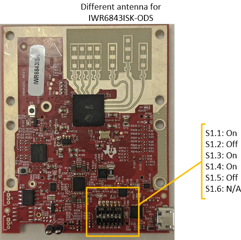
### Flashing Mode for Standalone ISK Style EVM's
1. Set the mux switches as shown in the image below
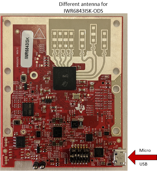
2. Connect the micro-USB cable to the EVM at the connector shown and
then to a PC. Note that a separate power supply is not needed as
the modules get power from the USB connection
itself. LEDs on the EVM should turn on.
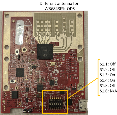
### Functional Mode for Standalone ISK Style EVM's
1. Set the mux switches as shown in the image below
2. Connect the micro-USB cable to the EVM at the connector shown and
then to a PC. Note that a separate power supply is not needed as
the modules get power from the USB connection
itself. LEDs on the EVM should turn on.

+]]
## ISK Style With mmWaveICBoost Attached
This section describes setting an ISK style EVM to either Flashing or
Functional mode when attached to an mmWaveICBoost carrier board.
[[+d Expand for steps for the ISK Style EVM's with an mmWaveICBoost
### Hardware Requirements for ISK + Carrier
* [MMWAVEICBOOST Carrier Board](http://www.ti.com/tool/MMWAVEICBOOST)
* ISK, ISK-ODS, or LEVM Antenna Module Board
* Micro USB Cable
* Power Supply 5V, 3A with 2.1-mm barrel jack (center positive)
### Initial Configuration for ISK Style EVM + Carrier
1. Configure mmWaveIcBoost
If the mmWaveICBoost carrier board has not been used previously,
then follow the [steps to perform initial configuration of the
carrier board.](#mmwaveicboost-initial-configuration)
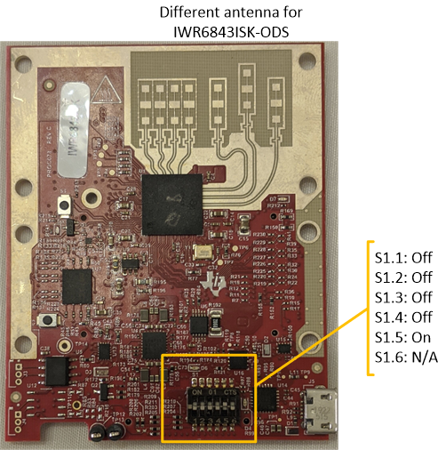
2. Configure Antenna Module
On *newer* EVM's (ISK Rev C or later and ISK-ODS Rev B or Later)
that have not been previously used in conjunction with the carrier
board, set the S1 Switches according to the following image
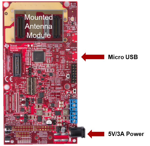
3. Mount EVM
* If using an older revision of the ISK or ODS module, both 60Pin
connectors will be used.
* If using a newer revision of the ISK or ISK-ODS module, only
the right connector closer to the micro-usb connectors will
be connected.
4. Connect cables
* Connect the micro-USB to the carrier board at the connector
shown and to the PC. Note that the micro-USB is connected
to the lower XDS110 USB (and not the FTDI USB).
* Connect the 5V/3A power supply to the power source and then
to the carrier board. LEDs on the carrier board should turn on.
### Flashing Mode for ISK Style EVM + Carrier
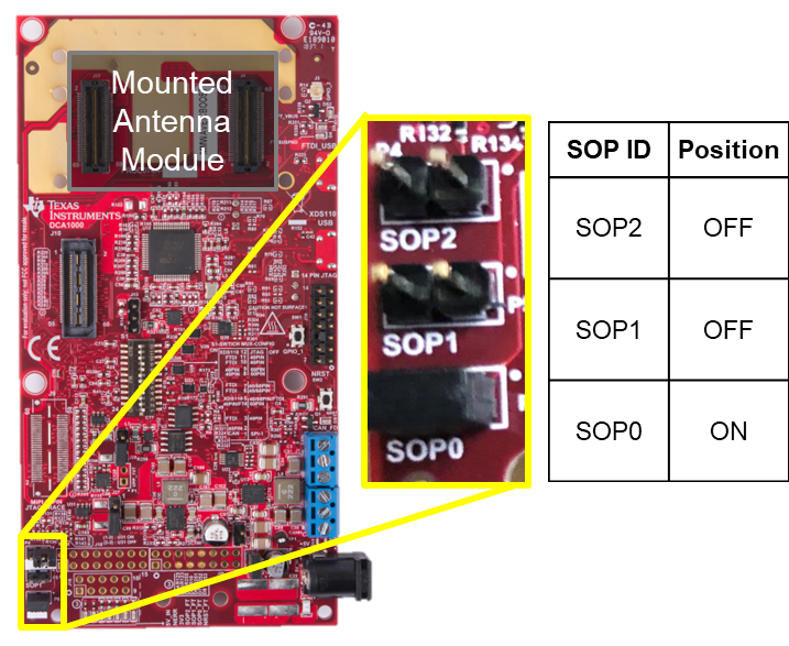
Set SOP mode jumpers according to the following image to
configure the carrier board for flashing mode.
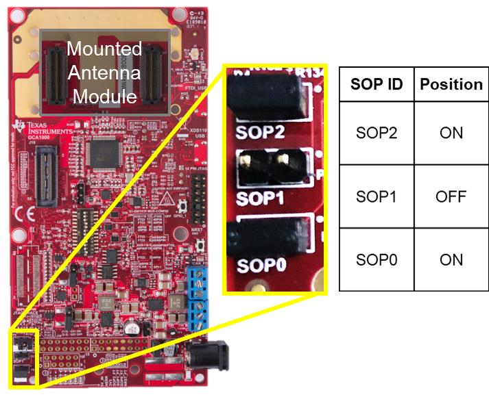
### Functional Mode for ISK Style EVM + Carrier
Set SOP mode jumpers according to the following image to
configure the carrier board for functional mode.
+]]
---
# AOP EVM's
This section applies to the following boards:
* [xWR6843AOPEVM](https://www.ti.com/tool/IWR6843AOPEVM)
## AOP Standalone Mode
* Section applies to setting an AOP EVM to Flashing or Functional
mode when used **without** an mmWaveICBoost carrier board.
* An AOP EVM can no longer be flashed if the board has been split at
the pre-made snap point.
* CCS Debug mode does **NOT** work in standalone mode.
[[+d Expand for steps for the Standalone AOP EVM's
### Hardware Requirements for Standalone AOP
* AOP Antenna Module Board
* Micro USB Cable
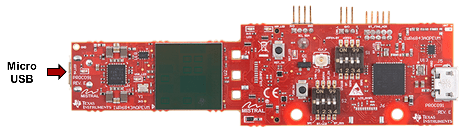
### Initial Configuration for Standalone AOP
If the device was previously used in standalone mode, this step
may be skipped. Otherwise, configure the S1 switches to match
the following image.
### Flashing Mode for Standalone AOP
1. Set the mux switches as described in the image below
2. Connect the micro-USB cable to the EVM at the connector shown and
then to a PC. Note that a separate power supply is not needed as
the AOP modules get power from the USB connection itself. LEDs
on the EVM should turn on.
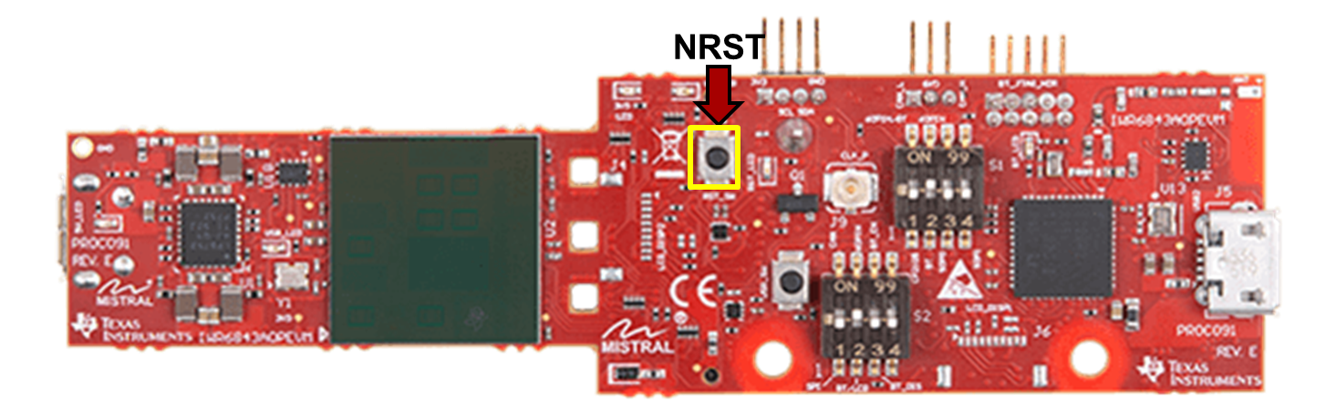
3. Toggle the NRST button to assert a device reset
### Functional Mode for Standalone AOP
1. Set the mux switches as described in the image below

2. Connect the micro-USB cable to the EVM at the connector shown and
then to a PC. Note that a separate power supply is not needed as
the AOP modules get power from the USB connection itself. LEDs
on the EVM should turn on.

3. Toggle the NRST button to assert a device reset

+]]
## AOP With mmWaveICBoost Attached
This section applies to setting an AOP EVM to Flashing or
Functional mode when attached to an mmWaveICBoost carrier board.
Please note, an AOP EVM cannot be attached to an mmWaveICBoost
carrier board once the board has been snapped at the pre-made
break point
[[+d Expand for steps for the AOP EVM's with an mmWaveICBoost
### 1. Hardware Requirements for AOP + Carrier
* [MMWAVEICBOOST Carrier Board](http://www.ti.com/tool/MMWAVEICBOOST)
* AOP Antenna Module Board
* Micro USB Cable
* Power Supply 5V, 3A with 2.1-mm barrel jack (center positive)
### 2. Initial Configuration for AOP + Carrier
1. Configure mmWaveIcBoost
If the mmWaveICBoost carrier board has not been used previously,
then follow the [steps to perform initial configuration of the
carrier board.](#mmwaveicboost-initial-configuration)
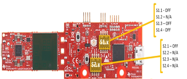
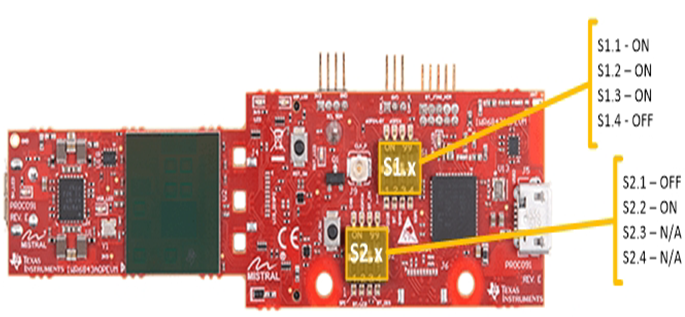
2. Configure Switches on Front of EVM
Set the S1 and S2 Switches on the front of the AOP EVM according
to the following image
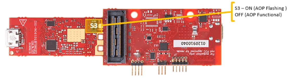
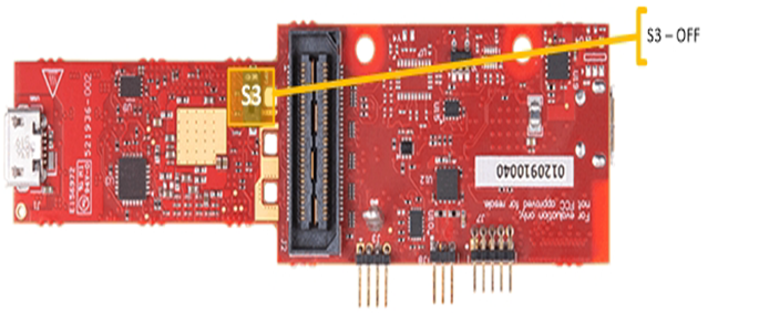
3. Configure Switch on Back of EVM
Set the S3 Switch on the back of the AOP EVM according to the
following image
4. Mount EVM
Attach the EVM to the carrier board. The 60 pin connector on
the AOP EVM will connect to the connector on the carrier that
is closer to the two micro-USB connectors
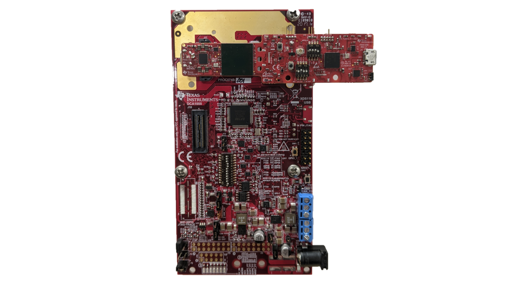
5. Connect cables
* Connect the micro-USB to the carrier board at the connector
shown and to the PC. Note that the micro-USB is connected
to the lower XDS110 USB (and not the FTDI USB).
* Connect the 5V/3A power supply to the power source and then
to the carrier board. LEDs on the carrier board should turn on.

### 3. Flashing Mode for AOP + Carrier
Set SOP mode jumpers according to the following image to
configure the carrier board for flashing mode.

### 4. Functional Mode for AOP + Carrier
Set SOP mode jumpers according to the following image to
configure the carrier board for functional mode.

+]]
---
# xWRxxxxBOOST EVM's
This section applies to the following boards:
* [xWR1443BOOST](https://www.ti.com/tool/IWR1443BOOST)
* [xWR1642BOOST](https://www.ti.com/tool/IWR1642BOOST)
* [xWR1843BOOST](https://www.ti.com/tool/IWR1843BOOST)
[[+d Expand for steps for xWRxxxxBOOST EVM's
## Hardware Requirements for BOOST EVM's
* BOOST EVM
* Micro USB Cable
* Power Supply 5V, 3A with 2.1-mm barrel jack (center positive)
## Flashing Mode for BOOST EVM's
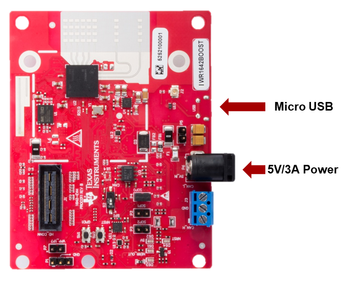
1. Connect Cables
* Connect the micro-USB to the PC and to the connector on the board
shown in the photo below.
* Connect the 5V/3A power supply to the power source and then
to the board. LEDs on the board should turn on.
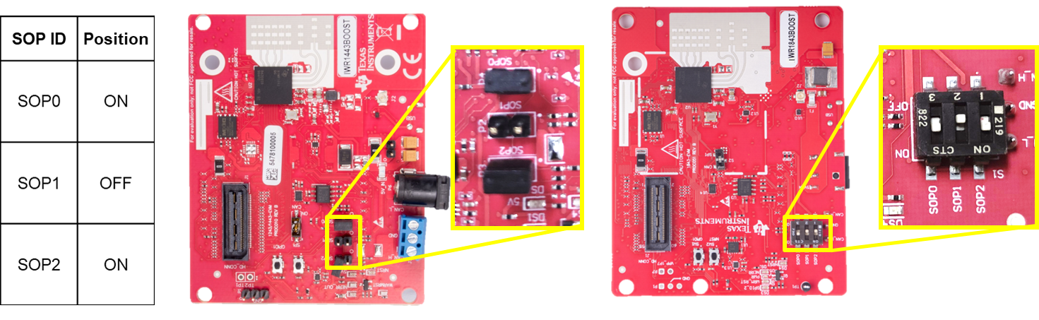
2. Set SOP Mode
Enable flashing mode by setting SOP2:0 to 101 as shown below.
Depending on the EVM, the board may have jumpers or switches to set
the SOP Mode - refer to the image corresponding to your EVM type.
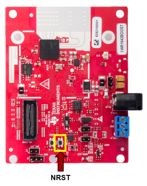
3. Toggle NRST
To ensure that the correct SOP mode is latched once power has been
applied, power cycle by pressing and releasing the NRST switch
identified below. The yellow DS4 LED below should toggle OFF and ON
when the switch is depressed then released.
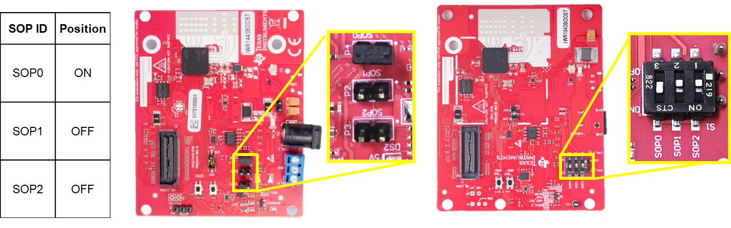
## Functional Mode for BOOST EVM's
1. Connect Cables
* Connect the micro-USB to the PC and to the connector on the board
shown in the photo below.
* Connect the 5V/3A power supply to the power source and then
to the board. LEDs on the board should turn on.

2. Set SOP Mode
Enable flashing mode by setting SOP2:0 to 101 as shown below.
Depending on the EVM, the board may have jumpers or switches to set
the SOP Mode - refer to the image corresponding to your EVM type.
3. Toggle NRST
To ensure that the correct SOP mode is latched once power has been
applied, power cycle by pressing and releasing the NRST switch
identified below. The yellow DS4 LED below should toggle OFF and ON
when the switch is depressed then released.

+]]
# Need More Help?
* Consult the [mmWaveICBoost and Antenna Module User's Guide](http://www.ti.com/lit/pdf/swru546)
* Search for your issue or post a new question on the [mmWave E2E forum](https://e2e.ti.com/support/sensor/mmwave_sensors/f/1023)