Introduction
This training module introduces the MSPM0 I2C, providing a standardized serial interface to transfer data between MSPM0 devices and other external I2C devices (such as a Sensors, Memory, or DACs). These lab activities are based on examples from the MSPM0 SDK driver library and are set up to do the following:
- Configure I2C as a target device and read/write multi-bytes using FIFO with polling
- Configure I2C as a controller device and read/write multi-bytes using FIFO with polling
- Configure I2C as a target device and read/write multi-bytes using FIFO with interrupts
- Configure I2C as a controller device and read/write multi-bytes using FIFO with interrupts
MSPM0L1306
Note: This academy was originally written for the LP-MSPM0G3507 but it will also work with the LP-MSPM0L1306 LaunchPad. There may be small differences in the MSPM0L1306 examples, such as pinouts and launchpad connections, but overall you should still be able to easily complete the included tasks.
Prerequisites
Before starting with this academy, it is recommended to start with the I2C curriculum in TI’s Precision Labs training series. to understand the fundamentals of the I2C functionality.
Hardware
The following hardware is required for this lab
- (2) MSPM0 LaunchPad
- BOOSTXL-BASSENSORS BoosterPack Module
- (2) Pull up resistors for SDA and SCL pins (optional)
Not required but recommended to help with understanding I2C communication
- Logic analyzer
Software
Installing the software
NOTE:
The software examples used in this lab should be imported from within the TI Resource Explorer. This can be accessed from the web or within CCS by clicking View→ Resource Explorer. To access TI Resource Explorer to import the examples into the Code Composer Studio (CCS) IDE, the M0 SDK must be installed on your PC. This may be done when CCS was installed or can be done later by clicking the "Download and Install" icon in the top right. Note that installing M0 SDK for any project will install ALL labs and content, so this only needs to be done once.
Recommended Resources
The documentation can be referenced for the MSPM0 MCU and the LaunchPad details.
These training videos provide a baseline introduction to the I2C protocol and hardware.
Overview
The MSPM0 I2C features an 8 byte FIFO, independent interrupts for controller and target modes, and support for DMA. The I2C interface supports the I2C Standard transmission speeds at 100 kbps, 400 kbps, and 1 Mbps, as well as SMBUS. For more details on the I2C, please refer to the MSPM0 datasheet and TRM above. This lab introduces I2C operations on MSP MCUs by building on the material introduced in I2C Precision Labs Training Series. Only the I2C initialization, operation, and interrupt handling portion of the code examples are the focus of this training academy. Other portions of the code examples related to the MCU's clock and GPIO initialization are presented for context and are left up to the reader to investigate separately through topic-specific TI Academy training.
This lab introduces fundamental I2C functionality on MSPM0 MCUs using MSPM0 LaunchPads and demonstrates the MSPM0 SDK Driverlib API to configure and operate the I2C. Only the I2C initialization, operation and interrupt handling portion of the code examples are the focus of this training academy. Other portions of the code example related to the MCU's clock and GPIO initialization are presented for context and are left up to the reader to investigate separately through topic-specific TI Academy training.
In this academy you will be using two LaunchPads; one as an I2C controller device, the other as an I2C target device. The examples demonstrate the use of the controller and target I2C devices' FIFO buffers, and the use of interrupts and CPU polling.
Getting Started
Hardware Setup:
To connect the MSPM0 launch pads for I2C communication:
- Attach the BOOSTXL-BASSENSOR module to either launchpad
- Using jumper wires, make 4 connections between the two LaunchPads.
- Choose one of the MSPM0 LaunchPads to be configured as the I2C controller device and the other as an I2C target device
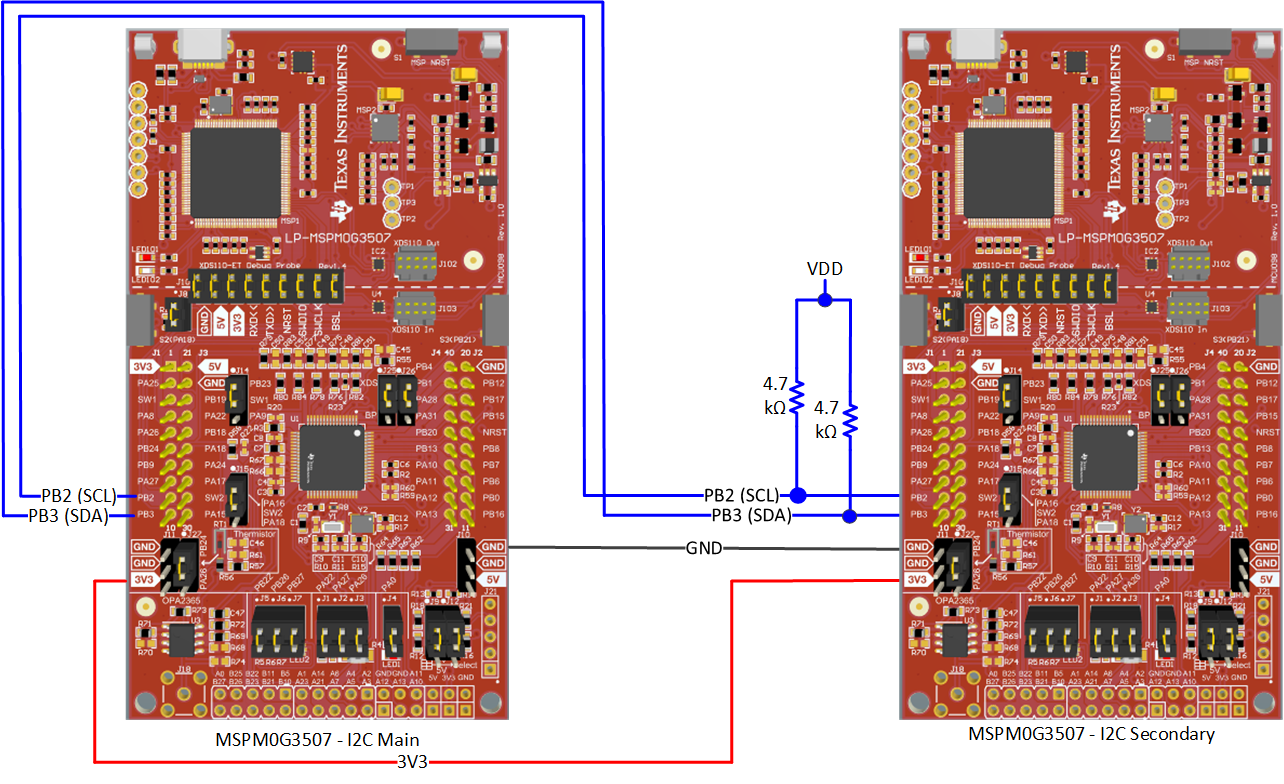
LaunchPad Wiring diagram:
Below is an electrical wiring diagram of the signals between the 2 MSPM0G3507 LaunchPads. Note, the I2C bus requires pull-up resistors on the SDA and SCL signals. The LaunchPad Boosterpack has integrated pull-up resistor, so attaching the Boosterpack to either MSPM0 LaunchPad will provide the necessary pull-ups.
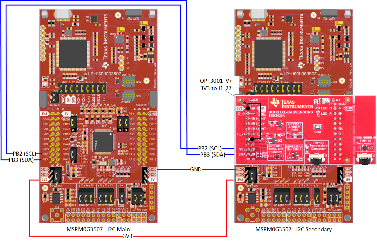
If, however, you don't have access to the the LaunchPad Boosterpack, connect (2) 4.7 kohm resistors to the boosterpack pins PB2 and PB3, as shown in the diagram.
- I2C1-SDA requires external pull-up resistor
- I2C1-SCL requires external pull-up resistor
Task 1 – I2C Target using FIFO with polling
Task 1 – Project Overview
This example demonstrates how Target I2C read and write transactions are performed, and can be used to validate I2C communication, or as a starting point to enable I2C functionality, or to create custom drivers. In this task there isn't any code to modify, so build and program the MSPM0 launchpad with the I2C target example.
- Import the I2C target example i2c_target_rw_multibyte_fifo_poll into CCS from TI Resource Explorer.
- MSPM0 SDK→ Examples→ Development Tools→ LP-MSPM0G3507 LaunchPad→ Driver Lib→ i2c_target_rw_multibyte_fifo_poll→ No RTOS→ TI Clang Compiler→
i2c_target_rw_multibyte_fifo_poll - Click import in the upper right hand corner
- MSPM0 SDK→ Examples→ Development Tools→ LP-MSPM0G3507 LaunchPad→ Driver Lib→ i2c_target_rw_multibyte_fifo_poll→ No RTOS→ TI Clang Compiler→
- Program the launchpad and designate this as your
I2C targetlaunchpad for the future tasks.
Note: For this example to work properly, the other MSPM0 LaunchPad must be programmed with the I2C Controller example code i2c_controller_rw_multibyte_fifo_poll and be enabled and active before running this example.
Task 1 – Code Overview
For this lab, the MSPM0 is programmed as an I2C Target, responding to write and read request from an I2C Controller. This example demonstrates the I2C Target FIFO buffer operation, and is limited to a maximum of 8 bytes due to FIFO size. The controller writes the target device's address, followed by 8-bytes. The target has pre-loaded its transmit FIFO buffer with 5 bytes, so during this time, it waits by using the CPU to poll and count each new byte received. When the controller writes the last byte, the target has counted 8-bytes, it will wait for the controller to read the 5 response bytes, using the CPU to poll and detect when the transmit FIFO is empty. When the controller reads back 5-bytes from the target, LED1 on the MSPM0 target board will toggle.
- LED1 will toggle periodically if transmission and reception were successful.
- LED1 will remain off if there is a problem during initialization.
- LED1 will remain on if there is a problem during data transfers.
The MSPM0 initialization and I2C configuration are done in the project file ti_msp_dl_config.c.
    SYSCONFIG_WEAK void SYSCFG_DL_GPIO_init(void)
    {

    DL_GPIO_initPeripheralInputFunctionFeatures(GPIO_I2C_0_IOMUX_SDA,
        GPIO_I2C_0_IOMUX_SDA_FUNC, DL_GPIO_INVERSION_DISABLE,
        DL_GPIO_RESISTOR_NONE, DL_GPIO_HYSTERESIS_DISABLE,
        DL_GPIO_WAKEUP_DISABLE);
    DL_GPIO_initPeripheralInputFunctionFeatures(GPIO_I2C_0_IOMUX_SCL,
        GPIO_I2C_0_IOMUX_SCL_FUNC, DL_GPIO_INVERSION_DISABLE,
        DL_GPIO_RESISTOR_NONE, DL_GPIO_HYSTERESIS_DISABLE,
        DL_GPIO_WAKEUP_DISABLE);
    DL_GPIO_enableHiZ(GPIO_I2C_0_IOMUX_SDA);
    DL_GPIO_enableHiZ(GPIO_I2C_0_IOMUX_SCL);

    DL_GPIO_initDigitalOutput(GPIO_LEDS_USER_LED_1_IOMUX);

    DL_GPIO_clearPins(GPIO_LEDS_PORT, GPIO_LEDS_USER_LED_1_PIN);
    DL_GPIO_enableOutput(GPIO_LEDS_PORT, GPIO_LEDS_USER_LED_1_PIN);

    }
GPIO Initialization
The I2C peripheral is configured to use the BUSCLK and is assigned a value of 0x48 as its target address.
    static const DL_I2C_ClockConfig gI2CClockConfig = {
        .clockSel = DL_I2C_CLOCK_BUSCLK,
        .divideRatio = DL_I2C_CLOCK_DIVIDE_1,
    };

    SYSCONFIG_WEAK void SYSCFG_DL_I2C_init(void) {

        DL_I2C_setClockConfig(I2C_INST,
            (DL_I2C_ClockConfig *) &gI2CClockConfig);
        DL_I2C_disableAnalogGlitchFilter(I2C_INST);

        /* Configure Target Mode */
        DL_I2C_setTargetOwnAddress(I2C_INST, I2C_TARGET_OWN_ADDR);
        DL_I2C_setTargetTXFIFOThreshold(I2C_INST, DL_I2C_TX_FIFO_LEVEL_EMPTY);
        DL_I2C_setTargetRXFIFOThreshold(I2C_INST, DL_I2C_RX_FIFO_LEVEL_BYTES_1);

        DL_I2C_enableTargetClockStretching(I2C_INST);
        /* Enable module */
        DL_I2C_enableTarget(I2C_INST);


    }
I2C Initialization
Transmit and receive buffers are created.
    /* Number of bytes to send from Target to Controller.
    *  The packet will be sent to the Controller during a Read request.
    *  This example uses FIFO with polling, and the maximum FIFO size is 8.
    *  Refer to interrupt examples to handle larger packets.
    */
   #define I2C_TX_PACKET_SIZE (5)

   /*
    * Number of bytes to receive from Controller.
    *  This example uses FIFO with polling, and the maximum FIFO size is 8.
    *  The example will wait until it receives all bytes.
    *  Refer to interrupt examples to handle larger packets
    */
   #define I2C_RX_PACKET_SIZE (8)

   /* Data sent to Controller in response to Read transfer */
   uint8_t gTxPacket[I2C_TX_PACKET_SIZE] = {'M', 'S', 'P', 'M', '0'};

   /* Data received from Controller during a Write transfer */
   uint8_t gRxPacket[I2C_RX_PACKET_SIZE];
Create TX and RX buffers
In main, the TXFIFO is filled with the 5 message bytes, then the CPU waits for a byte to be sent from the Controller. The target will wait for each byte to be received from the Controller, and when a byte is recieved, it is place into the receive buffer. After all 8 bytes have been received, the code enters a while-loop and toggles an LED to indicate the transaction is complete.
    /*
     * Fill FIFO with data.
     * Note that transactions are initiated by the Controller, so this function
     * only fills the buffer and the Target device will send this data when
     * requested by the Controller.
     */
    DL_I2C_fillTargetTXFIFO(I2C_0_INST, &gTxPacket[0], I2C_TX_PACKET_SIZE);

    /*
     * Wait to receive data from the Controller.
     * This loop expects I2C_RX_PACKET_SIZE bytes.
     */
    for (uint8_t i = 0; i < I2C_RX_PACKET_SIZE; i++) {
        while (DL_I2C_isTargetRXFIFOEmpty(I2C_0_INST))
            ;
        gRxPacket[i] = DL_I2C_receiveTargetData(I2C_0_INST);
    }

    /*
     * Wait until all bytes written to TX FIFO are sent after a successful
     * request.
     */
    while (!DL_I2C_isTargetTXFIFOEmpty(I2C_0_INST))
        ;

    /* If write and read were successful, toggle LED */
    while (1) {
        DL_GPIO_togglePins(GPIO_LEDS_PORT, GPIO_LEDS_USER_LED_1_PIN);
        delay_cycles(16000000);
    }
main()
If successful, LED1 toggles. But, if the controller only writes 7-bytes, what happens?
Task 2 – I2C Controller using FIFO with polling
Task 2 – Project Overview
This example shows a simple I2C transfer from Controller to Target. It can be used to validate I2C communication, as a starting point to control any I2C target, or to create custom drivers.
- Import the I2C controller example i2c_controller_rw_multibyte_fifo_poll from Resource Explorer.
MSPM0 SDK→ Examples→ Development Tools→ LP-MSPM0G3507 LaunchPad→ Driver Lib→ i2c_controller_rw_multibyte_fifo_poll→ No RTOS→ TI Clang Compiler→
i2c_controller_rw_multibyte_fifo_poll- Click import in the upper right hand corner
- Program the 2nd launchpad, designate this as our
I2C controllerlaunchpad
Note: For this example to work properly, the other MSPM0 LaunchPad must be programmed with the I2C Target example code i2c_target_rw_multibyte_fifo_poll and be enabled and active before running this example.
Task 2 – Code Overview
This MSPM0 is programmed as an I2C Controller and will demonstrate the use of a read/write FIFO to perform an I2C transaction by writing 8-bytes to the target I2C device, then read back 5-bytes. Note, due to its size, the FIFO is limited to a maximum of 8 bytes.
The controller writes the target device's address, followed by 8-bytes. During this time the controller uses the CPU to poll and detect when the transmit FIFO is empty. The target has pre-loaded its transmit FIFO buffer with 5 bytes, so it waits until all 8-bytes have been received. When the controller writes the last byte, it will then read back from the target 5-bytes. The controller uses the CPU to poll and count the number of bytes read. When the controller reads back 5-bytes from the target, LED1 on the MSPM0 controller board will toggle. Note, the Target device must be enabled and active before running the Controller example.
- LED1 will toggle periodically if transmission and reception were successful.
- LED1 will remain off if there is a problem during initialization.
- LED1 will remain on if there is a problem during data transfers.
The MSPM0 initialization and I2C configuration are done in the project file ti_msp_dl_config.c.
    SYSCONFIG_WEAK void SYSCFG_DL_GPIO_init(void)
    {
    DL_GPIO_initPeripheralInputFunctionFeatures(GPIO_I2C_0_IOMUX_SDA,
        GPIO_I2C_0_IOMUX_SDA_FUNC, DL_GPIO_INVERSION_DISABLE,
        DL_GPIO_RESISTOR_NONE, DL_GPIO_HYSTERESIS_DISABLE,
        DL_GPIO_WAKEUP_DISABLE);
    DL_GPIO_initPeripheralInputFunctionFeatures(GPIO_I2C_0_IOMUX_SCL,
        GPIO_I2C_0_IOMUX_SCL_FUNC, DL_GPIO_INVERSION_DISABLE,
        DL_GPIO_RESISTOR_NONE, DL_GPIO_HYSTERESIS_DISABLE,
        DL_GPIO_WAKEUP_DISABLE);
    DL_GPIO_enableHiZ(GPIO_I2C_0_IOMUX_SDA);
    DL_GPIO_enableHiZ(GPIO_I2C_0_IOMUX_SCL);

    DL_GPIO_initDigitalOutput(GPIO_LEDS_USER_LED_1_IOMUX);

    DL_GPIO_clearPins(GPIO_LEDS_PORT, GPIO_LEDS_USER_LED_1_PIN);
    DL_GPIO_enableOutput(GPIO_LEDS_PORT, GPIO_LEDS_USER_LED_1_PIN);
    }
GPIO Initialization
The I2C peripheral is configured as a Controller with a specified timeout value.
    static const DL_I2C_ClockConfig gI2CClockConfig = {
        .clockSel = DL_I2C_CLOCK_BUSCLK,
        .divideRatio = DL_I2C_CLOCK_DIVIDE_1,
    };

    SYSCONFIG_WEAK void SYSCFG_DL_I2C_0_init(void) {

        DL_I2C_setClockConfig(I2C_0_INST,
            (DL_I2C_ClockConfig *) &gI2C_0ClockConfig);
        DL_I2C_disableAnalogGlitchFilter(I2C_0_INST);

        /* Configure Controller Mode */
        DL_I2C_resetControllerTransfer(I2C_0_INST);
        /* Set frequency to 400000 Hz*/
        DL_I2C_setTimerPeriod(I2C_0_INST, 7);
        DL_I2C_setControllerTXFIFOThreshold(I2C_0_INST, DL_I2C_TX_FIFO_LEVEL_EMPTY);
        DL_I2C_setControllerRXFIFOThreshold(I2C_0_INST, DL_I2C_RX_FIFO_LEVEL_BYTES_1);
        DL_I2C_enableControllerClockStretching(I2C_0_INST);


        /* Enable module */
        DL_I2C_enableController(I2C_0_INST);
    }
I2C Initialization
Transmit and receive buffers are created.
    /*
     * Number of bytes to send from Controller to target.
     *  This example uses FIFO with polling, and the maximum FIFO size is 8.
     *  Refer to interrupt examples to handle larger packets
     */
    #define I2C_TX_PACKET_SIZE (8)

    /*
     * Number of bytes to received from target.
     *  This example uses FIFO with polling, and the maximum FIFO size is 8.
     *  Refer to interrupt examples to handle larger packets
     */
    #define I2C_RX_PACKET_SIZE (5)

    /* Data sent to the Target */
    uint8_t gTxPacket[I2C_TX_PACKET_SIZE] = {
        0x01, 0x02, 0x03, 0x04, 0x05, 0x06, 0x07, 0x08};

    /* Data received from Target */
    volatile uint8_t gRxPacket[I2C_RX_PACKET_SIZE];

    /* I2C Target address */
    #define I2C_TARGET_ADDRESS (0x48)
Create TX and RX buffers
In the first part of main, the TXFIFO is filled with the 8 bytes, then a transfer is started. While the bytes are being sent to the target, the controller will wait until the I2C is not busy, then check to see if any errors occurred. If there are errors, the code will remain in a while-loop with the LED on. After all 8 bytes have been received, the code enters a while-loop and toggles an LED to indicate the transaction is complete. In the second part, the controller will read 5 bytes, waiting as each byte is recieved. If no errors were detected, the code enters a while-loop and toggles an LED to indicate the transaction is complete.
    /*
     * Fill FIFO with data. This example will send a MAX of 8 bytes since it
     * doesn't handle the case where FIFO is full
     */
    DL_I2C_fillControllerTXFIFO(I2C_0_INST, &gTxPacket[0], I2C_TX_PACKET_SIZE);

    /* Wait for I2C to be Idle */
    while (!(DL_I2C_getControllerStatus(I2C_0_INST) &
             DL_I2C_CONTROLLER_STATUS_IDLE))
        ;

    /* Send the packet to the controller.
     * This function will send Start + Stop automatically.
     */
    DL_I2C_startControllerTransfer(I2C_0_INST, I2C_TARGET_ADDRESS,
        DL_I2C_CONTROLLER_DIRECTION_TX, I2C_TX_PACKET_SIZE);

    /* Poll until the Controller writes all bytes */
    while (DL_I2C_getControllerStatus(I2C_0_INST) &
           DL_I2C_CONTROLLER_STATUS_BUSY_BUS)
        ;

    /* Trap if there was an error */
    if (DL_I2C_getControllerStatus(I2C_0_INST) &
        DL_I2C_CONTROLLER_STATUS_ERROR) {
        /* LED will remain high if there is an error */
        __BKPT(0);
    }

    /* Wait for I2C to be Idle */
    while (!(DL_I2C_getControllerStatus(I2C_0_INST) &
             DL_I2C_CONTROLLER_STATUS_IDLE))
        ;

    /* Send a read request to Target */
    DL_I2C_startControllerTransfer(I2C_0_INST, I2C_TARGET_ADDRESS,
        DL_I2C_CONTROLLER_DIRECTION_RX, I2C_RX_PACKET_SIZE);

    /*
     * Receive all bytes from target. LED will remain high if not all bytes
     * are received
     */
    for (uint8_t i = 0; i < I2C_RX_PACKET_SIZE; i++) {
        while (DL_I2C_isControllerRXFIFOEmpty(I2C_0_INST))
            ;
        gRxPacket[i] = DL_I2C_receiveControllerData(I2C_0_INST);
    }

    /* If write and read were successful, toggle LED */
    while (1) {
        DL_GPIO_togglePins(GPIO_LEDS_PORT, GPIO_LEDS_USER_LED_1_PIN);
        delay_cycles(16000000);
    }
main()
If the controller LED1 does not toggle and remains on steady, what went wrong?
Task 3 – I2C Target using FIFO with interrupts
Task 3 – Project Overview
This example shows how to enable simple I2C read and write transactions for a target device. It can be used to validate I2C communication, as a starting point to enable I2C functionality, or to create custom drivers. In this task you won't be modifying anything, so build and program the MSPM0 launchpad with the I2C target example.
- Import the I2C target example i2c_target_rw_multibyte_fifo_interrupts into CCS from TI Resource Explorer.
- MSPM0 SDK→ Examples→ Development Tools→ LP-MSPM0G3507 LaunchPad→ Driver Lib→ i2c_target_rw_multibyte_fifo_interrupts→ No RTOS→ TI Clang Compiler→
i2c_target_rw_multibyte_fifo_interrupts - Click import in the upper right hand corner
- MSPM0 SDK→ Examples→ Development Tools→ LP-MSPM0G3507 LaunchPad→ Driver Lib→ i2c_target_rw_multibyte_fifo_interrupts→ No RTOS→ TI Clang Compiler→
Program the launchpad and designate this as your
I2C targetlaunchpad for future tasks.Note: For this example to work properly, the other MSPM0 LaunchPad must be programmed with the I2C Controller example code i2c_controller_rw_multibyte_fifo_interrupts and be enabled and active before running this example.
Task 3 – Code Overview
For this lab, the MSPM0 is programmed as an I2C Target, responding to write and read request from an I2C Controller. This example demonstrates the I2C Target FIFO buffer operation using interrupts to read and write one byte at a time while the CPU remains in it's low-power state. The controller begins the transaction by writing the target device's address, followed by 8-bytes. As the target receives each byte, the CPU will wake from it's low-power state and jump to the ISR handler, where it retrieves the byte. When the controller reads bytes from the target I2C device, the target CPU will wake from it's low-power state and jump to the transmit portion of the ISR handler, where it loads the next byte to be tranmistted into the FIFO.
The MSPM0 initialization and I2C configuration are done in the project file ti_msp_dl_config.c.
    SYSCONFIG_WEAK void SYSCFG_DL_GPIO_init(void)
    {
    DL_GPIO_initPeripheralInputFunctionFeatures(GPIO_I2C_0_IOMUX_SDA,
        GPIO_I2C_0_IOMUX_SDA_FUNC, DL_GPIO_INVERSION_DISABLE,
        DL_GPIO_RESISTOR_NONE, DL_GPIO_HYSTERESIS_DISABLE,
        DL_GPIO_WAKEUP_DISABLE);
    DL_GPIO_initPeripheralInputFunctionFeatures(GPIO_I2C_0_IOMUX_SCL,
        GPIO_I2C_0_IOMUX_SCL_FUNC, DL_GPIO_INVERSION_DISABLE,
        DL_GPIO_RESISTOR_NONE, DL_GPIO_HYSTERESIS_DISABLE,
        DL_GPIO_WAKEUP_DISABLE);
    DL_GPIO_enableHiZ(GPIO_I2C_0_IOMUX_SDA);
    DL_GPIO_enableHiZ(GPIO_I2C_0_IOMUX_SCL);

    DL_GPIO_initDigitalOutput(GPIO_LEDS_USER_LED_1_IOMUX);

    DL_GPIO_clearPins(GPIO_LEDS_PORT, GPIO_LEDS_USER_LED_1_PIN);
    DL_GPIO_enableOutput(GPIO_LEDS_PORT, GPIO_LEDS_USER_LED_1_PIN);
    }
GPIO Initialization
The I2C peripheral is configured to use the BUSCLK and is assigned a value of 0x48 as its target address. Additionally, the FIFO is configured to trigger an interrupt after each byte is received or transmitted.
    static const DL_I2C_ClockConfig gI2CClockConfig = {
        .clockSel = DL_I2C_CLOCK_BUSCLK,
        .divideRatio = DL_I2C_CLOCK_DIVIDE_1,
    };

    SYSCONFIG_WEAK void SYSCFG_DL_I2C_0_init(void) {

        DL_I2C_setClockConfig(I2C_0_INST,
            (DL_I2C_ClockConfig *) &gI2C_0ClockConfig);
        DL_I2C_disableAnalogGlitchFilter(I2C_0_INST);

        /* Configure Target Mode */
        DL_I2C_setTargetOwnAddress(I2C_0_INST, I2C_0_TARGET_OWN_ADDR);
        DL_I2C_setTargetTXFIFOThreshold(I2C_0_INST, DL_I2C_TX_FIFO_LEVEL_BYTES_1);
        DL_I2C_setTargetRXFIFOThreshold(I2C_0_INST, DL_I2C_RX_FIFO_LEVEL_BYTES_1);

        /* Configure Interrupts */
        DL_I2C_enableInterrupt(I2C_0_INST,
                               DL_I2C_INTERRUPT_TARGET_RXFIFO_TRIGGER |
                               DL_I2C_INTERRUPT_TARGET_START |
                               DL_I2C_INTERRUPT_TARGET_STOP);

        /* Enable module */
        DL_I2C_enableTarget(I2C_0_INST);
    }
I2C Initialization
Transmit and receive buffers are created.
    /* Maximum size of TX packet */
    #define I2C_TX_MAX_PACKET_SIZE (16)

    /* Maximum size of RX packet */
    #define I2C_RX_MAX_PACKET_SIZE (16)

    /* Data sent to Controller in response to Read transfer */
    uint8_t gTxPacket[I2C_TX_MAX_PACKET_SIZE] = {0x00};

    /* Counters for TX length and bytes sent */
    uint32_t gTxLen, gTxCount;

    /* Data received from Controller during a Write transfer */
    uint8_t gRxPacket[I2C_RX_MAX_PACKET_SIZE];
    /* Counters for TX length and bytes sent */
    uint32_t gRxLen, gRxCount;
Create TX and RX buffers
In main, the I2C interrupts are enabled and the CPU enters its low-power sleep mode
    /*
     * Fill FIFO with data.
     * Note that transactions are initiated by the Controller, so this example
     * only fills the buffer and the Target device will send this data when
     * requested by the Controller.
     * The TX FIFO is initialized to zero and then it will echo the data sent
     * by Controller.
     */
    gTxCount = 0;
    gTxLen   = I2C_TX_MAX_PACKET_SIZE;
    DL_I2C_enableInterrupt(I2C_0_INST, DL_I2C_INTERRUPT_TARGET_TXFIFO_TRIGGER);

    /* Initialize variables to receive data inside RX ISR */
    gRxCount = 0;
    gRxLen   = I2C_RX_MAX_PACKET_SIZE;

    NVIC_EnableIRQ(I2C_0_INST_INT_IRQN);

    DL_SYSCTL_enableSleepOnExit();

    while (1) {
        __WFI();
    }
main()
The ISR uses a switch statement to direct the code execution to the appropriate section based on the interrupt vector value.
    switch (DL_I2C_getPendingInterrupt(I2C_0_INST)) {
        case DL_I2C_IIDX_TARGET_START:
            /* Initialize RX or TX after Start condition is received */
            gRxCount = 0;
            dataRx   = false;
            break;
        case DL_I2C_IIDX_TARGET_RXFIFO_TRIGGER:
            /* Store received data in buffer */
            dataRx = true;
            while (DL_I2C_isTargetRXFIFOEmpty(I2C_0_INST) != true) {
                if (gRxCount < gRxLen) {
                    gRxPacket[gRxCount++] =
                        DL_I2C_receiveTargetData(I2C_0_INST);
                } else {
                    /* Prevent overflow and just ignore data */
                    DL_I2C_receiveTargetData(I2C_0_INST);
                }
            }
            break;
        case DL_I2C_IIDX_TARGET_TXFIFO_TRIGGER:
            /* Fill TX FIFO if there are more bytes to send */
            if (gTxCount < gTxLen) {
                gTxCount += DL_I2C_fillTargetTXFIFO(
                    I2C_0_INST, &gTxPacket[gTxCount], (gTxLen - gTxCount));
            } else {
                /*
                 * Fill FIFO with 0x00 if more data is requested than
                 * expected gTxLen
                 */
                while (
                    DL_I2C_transmitTargetDataCheck(I2C_0_INST, 0x00) != false)
                    ;
            }
            break;
        case DL_I2C_IIDX_TARGET_STOP:
            /* If data was received, echo to TX buffer */
            if (dataRx == true) {
                for (uint16_t i = 0;
                     (i < gRxCount) && (i < I2C_TX_MAX_PACKET_SIZE); i++) {
                    gTxPacket[i] = gRxPacket[i];
                    DL_I2C_flushTargetTXFIFO(I2C_0_INST);
                }
                dataRx   = false;
                gTxCount = 0;
            }
            /* Toggle LED to indicate successful RX or TX */
            DL_GPIO_togglePins(GPIO_LEDS_PORT, GPIO_LEDS_USER_LED_1_PIN);
            break;
I2C Interrupt Handler()
In the ISR handler, how does the handler know which section of the code to execute?
Task 4 – I2C Controller using FIFO with interrupts
Task 4 – Project Overview
This example shows a simple I2C transfer from Controller to Target. It can be used to validate I2C communication, as a starting point to control any I2C target, or to create custom drivers.
- Import the I2C controller example i2c_controller_rw_mulibyte_fifo_interrupts from Resource Explorer.
MSPM0 SDK→ Examples→ Development Tools→ LP-MSPM0G3507 LaunchPad→ Driver Lib→ i2c_controller_rw_mulibyte_fifo_interrupts→ No RTOS→ TI Clang Compiler→
i2c_controller_rw_mulibyte_fifo_interrupts- Click import in the upper right hand corner
Program the 2nd launchpad, designate this our
I2C controllerlaunchpadNote: For this example to work properly, the other MSPM0 LaunchPad must be programmed with the I2C target example code i2c_target_rw_multibyte_fifo_interrupts and be enabled and active before running this example.
Task 4 – Code Overview
For this lab, the MSPM0 is programmed as an I2C Controller, demonstrating the I2C controller FIFO buffer operation using interrupts to write and read one byte at a time while the CPU remains in it's low-power state. In this example, the controller will write 16-bytes, then read back 16 bytes. Depending on the state of the I2C transaction, the code will jump to a location in the ISR handler based on the read or write interrupt and either read in or write out a byte. The LauchPad LED toggles if transmission and reception are successful.
- LED1 will toggle periodically if transmission and reception were successful.
- LED1 will remain off if there is a problem during initialization.
- LED1 will remain on if there is a problem during data transfers.
The MSPM0 initialization and I2C configuration are done in the project file ti_msp_dl_config.c.
    SYSCONFIG_WEAK void SYSCFG_DL_GPIO_init(void)
    {
    DL_GPIO_initPeripheralInputFunctionFeatures(GPIO_I2C_0_IOMUX_SDA,
        GPIO_I2C_0_IOMUX_SDA_FUNC, DL_GPIO_INVERSION_DISABLE,
        DL_GPIO_RESISTOR_NONE, DL_GPIO_HYSTERESIS_DISABLE,
        DL_GPIO_WAKEUP_DISABLE);
    DL_GPIO_initPeripheralInputFunctionFeatures(GPIO_I2C_0_IOMUX_SCL,
        GPIO_I2C_0_IOMUX_SCL_FUNC, DL_GPIO_INVERSION_DISABLE,
        DL_GPIO_RESISTOR_NONE, DL_GPIO_HYSTERESIS_DISABLE,
        DL_GPIO_WAKEUP_DISABLE);
    DL_GPIO_enableHiZ(GPIO_I2C_0_IOMUX_SDA);
    DL_GPIO_enableHiZ(GPIO_I2C_0_IOMUX_SCL);

    DL_GPIO_initDigitalOutput(GPIO_LEDS_USER_LED_1_IOMUX);

    DL_GPIO_clearPins(GPIO_LEDS_PORT, GPIO_LEDS_USER_LED_1_PIN);
    DL_GPIO_enableOutput(GPIO_LEDS_PORT, GPIO_LEDS_USER_LED_1_PIN);
    }
GPIO Initialization
The I2C peripheral is configured as a Controller with a specified timeout value, and interrupts are enabled, allowing the FIFO to trigger an interrupt after each byte is transmitted.
    SYSCONFIG_WEAK void SYSCFG_DL_I2C_0_init(void) {

        DL_I2C_setClockConfig(I2C_0_INST,
            (DL_I2C_ClockConfig *) &gI2C_0ClockConfig);
        DL_I2C_disableAnalogGlitchFilter(I2C_0_INST);

        /* Configure Controller Mode */
        DL_I2C_resetControllerTransfer(I2C_0_INST);
        /* Set frequency to 400000 Hz*/
        DL_I2C_setTimerPeriod(I2C_0_INST, 7);
        DL_I2C_setControllerTXFIFOThreshold(I2C_0_INST, DL_I2C_TX_FIFO_LEVEL_BYTES_1);
        DL_I2C_setControllerRXFIFOThreshold(I2C_0_INST, DL_I2C_RX_FIFO_LEVEL_BYTES_1);
        DL_I2C_enableControllerClockStretching(I2C_0_INST);

        /* Configure Interrupts */
        DL_I2C_enableInterrupt(I2C_0_INST,
                               DL_I2C_INTERRUPT_CONTROLLER_ARBITRATION_LOST |
                               DL_I2C_INTERRUPT_CONTROLLER_NACK |
                               DL_I2C_INTERRUPT_CONTROLLER_RXFIFO_TRIGGER |
                               DL_I2C_INTERRUPT_CONTROLLER_RX_DONE |
                               DL_I2C_INTERRUPT_CONTROLLER_TX_DONE);

        /* Enable module */
        DL_I2C_enableController(I2C_0_INST);
    }
I2C Initialization
Transmit and receive buffers are created.
    /* Maximum size of TX packet */
    #define I2C_TX_MAX_PACKET_SIZE (16)

    /* Number of bytes to send to target device */
    #define I2C_TX_PACKET_SIZE (16)

    /* Maximum size of RX packet */
    #define I2C_RX_MAX_PACKET_SIZE (16)

    /* Number of bytes to received from target */
    #define I2C_RX_PACKET_SIZE (16)

    /* I2C Target address */
    #define I2C_TARGET_ADDRESS (0x48)

    /* Data sent to the Target */
    uint8_t gTxPacket[I2C_TX_MAX_PACKET_SIZE] = {0x00, 0x01, 0x02, 0x03, 0x04,
        0x05, 0x06, 0x07, 0x08, 0x09, 0x0A, 0x0B, 0x0C, 0x0D, 0x0E, 0x0F};
    /* Counters for TX length and bytes sent */
    uint32_t gTxLen, gTxCount;

    /* Data received from Target */
    uint8_t gRxPacket[I2C_RX_MAX_PACKET_SIZE];
    /* Counters for TX length and bytes sent */
    uint32_t gRxLen, gRxCount;
Create TX and RX buffers
In the first part of main, the TXFIFO is filled with 8 bytes. An interrupt is enabled if there are more bytes to send. The bytes are then sent, and the controller checks for errors. If there are errors, the code will remain in a while-loop with the LED on. In the second part, a read request is sent to the Target, and the Controller waits for all the bytes to be received in interrupt. If no errors were detected, the code enters a while-loop and toggles an LED to indicate the transaction is complete.
    NVIC_EnableIRQ(I2C_0_INST_INT_IRQN);
    DL_SYSCTL_disableSleepOnExit();

    gI2cControllerStatus = I2C_STATUS_IDLE;

    gTxLen = I2C_TX_PACKET_SIZE;
    /*
     * Fill the FIFO
     *  The FIFO is 8-bytes deep, and this function will return number
     *  of bytes written to FIFO */
    gTxCount = DL_I2C_fillControllerTXFIFO(I2C_0_INST, &gTxPacket[0], gTxLen);
    /* Enable TXFIFO trigger interrupt if there are more bytes to send */
    if (gTxCount < gTxLen) {
        DL_I2C_enableInterrupt(
            I2C_0_INST, DL_I2C_INTERRUPT_CONTROLLER_TXFIFO_TRIGGER);
    } else {
        DL_I2C_disableInterrupt(
            I2C_0_INST, DL_I2C_INTERRUPT_CONTROLLER_TXFIFO_TRIGGER);
    }

    /*
     * Send the packet to the controller.
     * This function will send Start + Stop automatically.
     */
    gI2cControllerStatus = I2C_STATUS_TX_STARTED;
    while (!(DL_I2C_getControllerStatus(I2C_0_INST) &
             DL_I2C_CONTROLLER_STATUS_IDLE))
        ;
    DL_I2C_startControllerTransfer(I2C_0_INST, I2C_TARGET_ADDRESS,
        DL_I2C_CONTROLLER_DIRECTION_TX, gTxLen);

    /* Wait until the Controller sends all bytes */
    while ((gI2cControllerStatus != I2C_STATUS_TX_COMPLETE) &&
           (gI2cControllerStatus != I2C_STATUS_ERROR)) {
        __WFE();
    }

    while (DL_I2C_getControllerStatus(I2C_0_INST) &
           DL_I2C_CONTROLLER_STATUS_BUSY_BUS)
        ;

    /* Trap if there was an error */
    if (DL_I2C_getControllerStatus(I2C_0_INST) &
        DL_I2C_CONTROLLER_STATUS_ERROR) {
        /* LED will remain high if there is an error */
        __BKPT(0);
    }

    while (!(DL_I2C_getControllerStatus(I2C_0_INST) &
             DL_I2C_CONTROLLER_STATUS_IDLE))
        ;
    /* Send a read request to Target */
    gRxLen               = I2C_RX_PACKET_SIZE;
    gRxCount             = 0;
    gI2cControllerStatus = I2C_STATUS_RX_STARTED;
    DL_I2C_startControllerTransfer(I2C_0_INST, I2C_TARGET_ADDRESS,
        DL_I2C_CONTROLLER_DIRECTION_RX, gRxLen);

    /* Wait for all bytes to be received in interrupt */
    while (gI2cControllerStatus != I2C_STATUS_RX_COMPLETE) {
        __WFE();
    }

    while (DL_I2C_getControllerStatus(I2C_0_INST) &
           DL_I2C_CONTROLLER_STATUS_BUSY_BUS)
        ;

    /* If write and read were successful, toggle LED */
    while (1) {
        DL_GPIO_togglePins(GPIO_LEDS_PORT, GPIO_LEDS_USER_LED_1_PIN);
        delay_cycles(16000000);
    }
main()
The ISR uses a switch statement to direct the code execution to the appropriate section based on the interrupt vector value.
    switch (DL_I2C_getPendingInterrupt(I2C_0_INST)) {
        case DL_I2C_IIDX_CONTROLLER_RX_DONE:
            gI2cControllerStatus = I2C_STATUS_RX_COMPLETE;
            break;
        case DL_I2C_IIDX_CONTROLLER_TX_DONE:
            DL_I2C_disableInterrupt(
                I2C_0_INST, DL_I2C_INTERRUPT_CONTROLLER_TXFIFO_TRIGGER);
            gI2cControllerStatus = I2C_STATUS_TX_COMPLETE;
            break;
        case DL_I2C_IIDX_CONTROLLER_RXFIFO_TRIGGER:
            gI2cControllerStatus = I2C_STATUS_RX_INPROGRESS;
            /* Receive all bytes from target */
            while (DL_I2C_isControllerRXFIFOEmpty(I2C_0_INST) != true) {
                if (gRxCount < gRxLen) {
                    gRxPacket[gRxCount++] =
                        DL_I2C_receiveControllerData(I2C_0_INST);
                } else {
                    /* Ignore and remove from FIFO if the buffer is full */
                    DL_I2C_receiveControllerData(I2C_0_INST);
                }
            }
            break;
        case DL_I2C_IIDX_CONTROLLER_TXFIFO_TRIGGER:
            gI2cControllerStatus = I2C_STATUS_TX_INPROGRESS;
            /* Fill TX FIFO with next bytes to send */
            if (gTxCount < gTxLen) {
                gTxCount += DL_I2C_fillControllerTXFIFO(
                    I2C_0_INST, &gTxPacket[gTxCount], gTxLen - gTxCount);
            }
            break;
            /* Not used for this example */
        case DL_I2C_IIDX_CONTROLLER_ARBITRATION_LOST:
        case DL_I2C_IIDX_CONTROLLER_NACK:
            if ((gI2cControllerStatus == I2C_STATUS_RX_STARTED) ||
                (gI2cControllerStatus == I2C_STATUS_TX_STARTED)) {
                /* NACK interrupt if I2C Target is disconnected */
                gI2cControllerStatus = I2C_STATUS_ERROR;
            }
I2C Interrupt Handler()
What is the maximum number of bytes supported by the FIFO?
Summary
At the end of this lab, you should now be able to:
- Transmit and receive data with I2C via polling
- Transmit and receive data with I2C via interrupts
This work is licensed under a Creative Commons Attribution-NonCommercial-NoDerivatives 4.0 International License.