Introduction
The purpose of this exercise is to familiarize the users with the RF driver, Code Composer Studio and SmartRF™ Studio, by importing and modifying existing RX & TX example applications.
Task 1: Send and receive packets with SmartRF Studio.
Task 2: Import and run an existing TX example with Code Composer Studio.
Task 3: Export RF settings from SmartRF Studio to Code Composer Studio example application.
Task 4: Send data from firmware, receive it using SmartRF Studio.
Task 5: Import and modify an existing RX example with Code Composer Studio.
Task 6: Send data from SmartRF Studio and receive it with the firmware.
Task 7: Test two LaunchPads with the flashed TX and RX firmware.
Technical support
For any questions you may have, please have a look at the relevant E2E forums: TI Sub-1 GHz E2E Forum, TI 2.4 GHz Proprietary E2E Forum
SysConfig support
Since 3Q 2019, with SDK version 3.30, SysConfig-enabled versions of examples are provided for CC26X2 and CC13X2 devices. Currently, SysConfig is not available for the other devices.
Prerequisites
Background
- Basic TI-RTOS and CCS knowledge.
- Some basic familiarity with embedded programming.
Software
In order to start with this exercise you will need to download the correct Software Development Kit (SDK) for your LaunchPad.
For CC13x0:
- SimpleLink CC13x0 SDK 3.10 or later. Note: SysConfig is not available for this device.
For CC13x2:
- SimpleLink CC13x2 26x2 SDK 3.30 or later. (Any older version does not support SysConfig)
For CC2640R2:
- SimpleLink CC2640R2 SDK 3.10 or later. Note: SysConfig is not available for this device.
The following software applies for both device families:
- Code Composer Studio 9.2 or higher. (Any older version does not support SysConfig)
Make sure that CCS is using the latest updates: Help → Check for Updates
- SmartRF™ Studio 2.12.1 or later.
Hardware
- 2 x CC13xx LaunchPads OR 2 x CC2640R2 LaunchPads
In case you need to use LaunchPads from different CC13xx families, make sure the correct projects are downloaded to the devices.
Note
This lab can be performed using either CC1310, CC1312, CC1350, CC1352P, CC1352R or CC2640R2 LaunchPads. The training material is based on a CC1310 LaunchPad, but for this training the steps and procedures are the same regardless of which of the supported LaunchPads that are used.
The parts of this training dealing with SysConfig cannot be achieved with a CC1310 LaunchPad (SysConfig is not available on this device). In this case, we used a CC1312 LaunchPad.
When using the CC2640R2 LaunchPads, the radio settings will be different compared to that of the CC13xx devices. When device specific actions are required this will be highlighted in the related section.
Group training additional requirements
Make sure to always use your designated frequency, to avoid interfering with other students' operations
Frequency allocation
If you are part of a group training, please ask the instructor for a unique frequency to use during this lab.
For simplicity, it is possible to use a base frequency (2440.0, 915.0, 868.0, 433.0), allocate a running number to each of the students and have each student multiply their number by 100 kHz channel spacing. For example, student #5 would then use 868 + 0.1*5 = 868.5 MHz.
Documentation and SmartRF™ Studio
This lab introduces SmartRF Studio and explains the basic usage of the TI-RTOS RF driver.
Documentation
The main documentation related to the RF core is in the Technical Reference Manual. It contains detailed information about the CC13xx and CC2640R2 as well as how to use the peripheral units. The "Radio" chapter focuses on the radio core, and we recommend to read it before doing the training.
SmartRF™ Studio
SmartRF Studio is used to test and evaluate RF settings on the CC13xx and CC2640R2 device. It can also send and receive packets when connected to a device. SmartRF Studio uses radio operation commands as described in the Radio section of the Technical Reference Manual.
For example, if we send one single packet in SmartRF studio (don't worry, you'll learn how to do this later) then the content of the Command View will look like the image below:
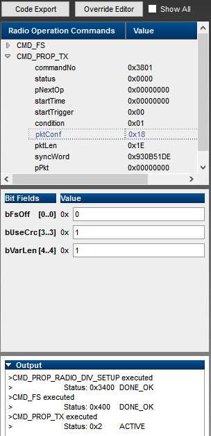
In the bottom part of this picture we can see exactly which commands were sent. In the top view we can explore the content of those commands.
Please note that the content of the command in the top view correlate exactly to that of the documentation. If you click on a specific field, then even the bit fields are shown and easy to edit.
Code Export
In order to use a specific RF configuration in a TI-RTOS application, the settings must be exported as command structures in C code. This is done via the Code Export button in SmartRF Studio.
SysConfig allows you to directly generate the radio settings (we will discuss
this later in this lab). The radio settings are directly written in
ti_radio_config.h/.c. As a consequence there is no point to use
SmartRF™ Studio to do so.
Do not edit the configuration files
As the config files are generated at each build by SysConfig it is useless to modify the content of those files (your modification will be overwritten at each build). If you need to modify the files generated by SysConfig (to use the configuration files provided by SmartRF™ Studio for example), please follow the procedure described in the Proprietary RF User’s Guide in the SysConfig chapter.
The exported code can then be used directly in any TI-RTOS project. In the
rfPacketTx example that we discuss throughout this hands-on, the exported
settings are found in smartrf_settings.h/.c. These structs
contain application-specific fields such as triggers and pointers to the
actual data that need to be set in the application source code.
Summary
- The Technical Reference Manual describes radio operation commands.
- SysConfig (when available) allows to directly generate the radio operation commands. SmartRF Studio can be used to configure, test and export the radio operation commands as C structs.
- The TI-RTOS application overwrites application-specific command fields and executes the commands using the RF driver.
TI-RTOS RF Driver (rflib)
In a TI-RTOS application, the RF core is accessed exclusively via the RF driver. This driver provides functions to set up the RF core and to execute various radio commands which are divided into three groups:
- Immediate commands
- Direct commands
- Radio operation commands
Immediate and direct commands execute immediately and return a result upon completion. They are protocol-independent and often used to configure the RF core and to interact with running radio operation commands. Radio operation commands, in contrast, are more complex. They support various triggers and may also be chained together to create more sophisticated commands. In this tutorial, we will only use radio operation commands.
API
The RF driver documentation is installed as part of the MCU SDK. To access it, please refer to your SDK installation folder. If you chose the default settings during the installation process, then the location would be similar to this:
<SDK folder>\docs\\docs\rflib\html\index.html
For convenience, the RF Driver APIs are briefly listed here:
| API function | Description |
|---|---|
| RF_open() | Open client connection to RF driver and return a command handle |
| RF_close() | Close client connection to RF driver |
| RF_postCmd() | Execute a radio operation command asynchronously or append it to the command queue if another command is already running |
| RF_scheduleCmd() | Schedules a radio operation into the command queue based on the given scheduling parameters. Only available as part of the "multi-mode" RF Driver. |
| RF_pendCmd() | Wait for previously posted command to complete |
| RF_runCmd() | Execute a radio operation command synchronously and wait for its completion |
| RF_cancelCmd() | Abort a currently running command |
| RF_flushCmd() | Abort a currently running command and clear the command queue |
| RF_runDirectCmd() | Execute a direct command synchronously |
| RF_runImmediateCmd() | Execute an immediate command synchronously |
Task 0: Label your LaunchPads
Label each of your LaunchPads with its XDS Device ID, as described here.
Additionally, label one LaunchPad as "RX" and the other as "TX". These labels will be referred to throughout this lab. It is recommended to use a non-permanent marking for this (e.g. sticky notes), as these labels may only be relevant for this specific lab.
Task 1: SmartRF Studio ↔ SmartRF Studio
SmartRF Studio can be used to test RF settings and to evaluate those settings by sending and receiving packets. This task will take you through the process of testing a complete TX / RX link by sending packets between two CC13xx (or CC2640R2) LaunchPads using only SmartRF Studio. No additional software or firmware is needed.
Connecting SmartRF Studio
Have both LaunchPads connected to the PC and powered on. Make sure that no other program, such as CCS or a serial port monitor, is currently accessing the LaunchPads.
Check this:
The green LED of the LaunchPads' XDS Emulator (the LED closer to the USB connector) should light up, to indicate that the boards are powered on.
Open SmartRF Studio 7
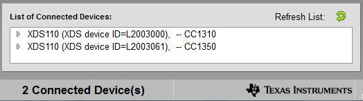
The devices should automatically show up in the device listing at the bottom. If not, click on the green arrow next to Refresh list. If everything works and both boards are detected then you will see two boards in the device listing.
Double-click on one of the devices in the device listing. A pop-up will open, asking you to select the operation mode:
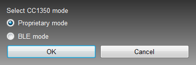
select Proprietary mode, and this should open up the Device Control Panel.
Navigate back to the SmartRF Studio main window and double click on the other device as well. The one that is already connected will say DC-Panel Open, so double-click on the other one. Select Proprietary mode, if several modes are available (depends on the device).
Congratulations!
You have successfully connected SmartRF Studio to two different targets. You should see one main SmartRF Studio window as well as two Device Control Panel windows.
Configuring RX and TX
PHY Modes
For the CC13x0 devices, Texas Instruments has characterized the following RF modes, which are also referred to as a PHY:
- 50, 200, 300, 400, 500 kbps (2-GFSK)
- 50 kbps IEEE 802.15.4g MR-FSK (2-GFSK)
- Legacy Long Range: 625 bps (DSSS).
- SimpleLink Long Range: 2.5 and 5 kbps (DSSS)
- WB-DSSS at 240, 120, 60 or 30 kbps (2-GFSK, 1x, 2x, 4x or 8x spreading)
- High-Speed mode, 4 Mbps (not supported by SmartRF Studio).
- Legacy CC11xx settings: OOK, 4.8 and 10 kbps.
For the CC13x2 devices, Texas Instruments has characterized the following RF modes:
- 50 kbps (2-GFSK)
- 50 kbps IEEE 802.15.4g MR-FSK (2-GFSK)
- 200 kpbs IEEE 802.15.4 FSK
- SimpleLink Long Range: 2.5 and 5 kbps (DSSS)
50 kbps mode (2-GFSK) is the default setting for both device families.
For the CC2640R2 device, Texas Instruments har characterized the following RF modes:
- 100, 250 kbps (2-GFSK)
The 100 kbps mode (2-GFSK) is the default setting for the CC2640R2 device.
Packet format
The RF core on the CC13xx and CC2640R2 provides a flexible packet engine which allows to:
- adjust length and content for both preamble and syncword
- use packets with fixed or variable length (through a length field)
- apply address filters to the packet (with the address field following the length byte)
- configure a CRC check
| Preamble | Sync word | Length | Payload | CRC | |
|---|---|---|---|---|---|
| Size | 4 bytes | 4 bytes | 1 byte | N bytes | 2 bytes |
| Content | 0x55555555 | 0x930b51de | N (max 255) | Application specific | 0xXXYY |
SmartRF Studio inserts a 2 byte sequence number as the first two bytes of the payload. This is optional and is used to calculate the Packet Error Rate ( PER). The rest of the payload consists of either random or user-supplied data.
Apply the settings
Next we will configure one SmartRF Studio in RX and the other in TX.
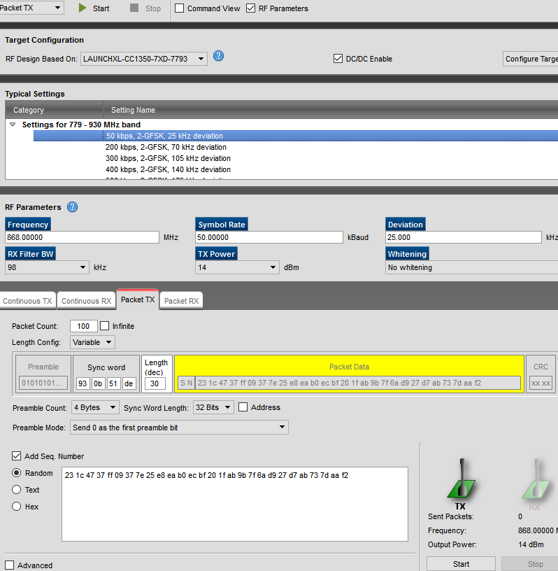
Both instances of the Device Control Panel should be displaying the Packet TX tab. This tab is used to transmit packets using the selected setting.
Change Frequency
If in a group, before doing anything else, please change the frequency (in the RF Parameters section) to your allocated frequency. Do this in both instances of the Device Control Panel.
Find the Device Control Panel that is connected to the "RX" LaunchPad, switch it to the Packet RX tab and press the Start button. This will set up the device in RX mode.
Which board is it?
To tell which LaunchPad is connected to which Device Control Panel, look at the window's title - it should specify the XDS Device ID of the connected device.
Next, switch to the Device Control Panel that is connected to the "TX" LaunchPad. The Packet TX tab should already be selected. Press Start. This will cause the device to send 100 packets.
Switch back to the Device Control Panel that is in RX mode, and watch the packets coming in.
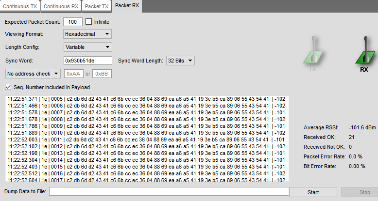
Observes the results
On the right side in the Packet RX tab you should see:
- The average RSSI.
- How many packets were received OK / Not OK.
- The PER (Packet Error Rate) and BER (Bit Error Rate).
Task 2: Importing and running the rfPacketTx example
In this task we will use Code Composer Studio to import, build, flash and run an existing CC13xx or CC2640R2 project.
The content of this lab is based on Code Composer Studio projects, but projects for IAR and GCC are also installed with the SDK.
Import an Existing Example Project
Follow these steps to import an existing example, rfPacketTx, into Code Composer Studio. When selecting SDK, make sure to select the SDK that relates to the device that is used.
Open Code Composer Studio (CCS), then in the menu, select View → Resource Explorer
Attention
Do not open Resource Explorer Classic (if it is an available option). In this task we will be working with the new Resource Explorer.
If this is the first time running Resource Explorer after installing the SimpleLink SDK, make sure it finds the SDK, and let it import it.
Expand the elements: Software → SimpleLink SDK → Examples → Development Tools → CC13xx LaunchPad → TI Drivers → rfPacketTx → TI-RTOS & rarr; CCS Compiler → rfPacketTx
Select CCS Compiler (i.e. click on CCS Compiler in the folder-tree view on the left). Your view should look similar to this:
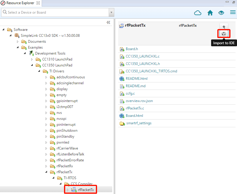
Click on Import to IDE icon in top right (see image above).
You have now imported the rfPacketTx example project
There should now be a new project in the Project Explorer called rfPacketTx_CCxxxx_LAUNCHXL_tirtos_ccs:
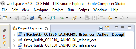
Note
The TIRTOS kernel is now included as a separate project imported with the example project. It can be seen above in the tirtos_builds_CCxxxx_LAUNCHXL_release_ccs project. The TIRTOS kernel project is specific to the board type and compiler and shared by all examples for that Board type / compiler.
Build and Run the Project
The rfPacketTx example illustrates how to do simple packet transmission using the TI-RTOS RF driver.
This example is meant to be used in cooperation either with the rfPacketRx example or with SmartRF Studio, as will be demonstrated in the following tasks. In the current task, we will verify its operation by watching the on-board LED.
Note
When trying to program or debug a connected target in Code Composer Studio, while the same target is opened in SmartRF Studio, CCS may occasionally crash. To prevent this, it is recommended to close SmartRF Studio at this point (if it is open).
Connect the "TX" LaunchPad to the PC, if not already connected.
Update the target of the rfPacketTX project to associate it with the "TX" LaunchPad - as explained here.
In CCS, build and download the example: Make sure that the rfPacketTx_CCxxxx_LAUNCHXL_tirtos_ccs project is selected in the project explorer, and then click "Debug" (shortcut F11):

When you click "Debug", the following operations are performed automatically:
- Open the CCS Debug view
- (If activated) SysConfig generates the config files
- Build the project if there has been any changes
- Flash the target
- Halt at the beginning of
main()
To run the program, wait for the build and download process to finish, then press the Resume button in the debug toolbar or Run → Resume ( F8).

Verify the program operation:
Watch the on-board LEDs
The green LED (DI07) on the LaunchPad toggles when data is transmitted over the RF interface.
Stop the debug session by pressing the Terminate button in the CCS' debug toolbar (or from the Run drop down menu). CCS will automatically return to the Edit view.
Task 3: Generating and using RF configuration using SysConfig or SmartRF™ Studio
For the following tasks, instead of using the default packet configuration, we will generate our own packet configuration. We will increase the symbol rate from 50 kbps to 100 kbps, which will in turn require modification of other parameters too.
These modifications can be done using SmartRF Studio (works for all the devices, require to export the new configuration from SmartRF Studio and include it in the application) or using SyscConfig (only applicable to CC13X2, the configuration is directly generated in the right file).
If using CC2640R2 LaunchPads
As 100 kbps is the default symbol rate when working with CC2640R2, we instead increase from 100 kbps to 200 kbps.
SysConfig can be used to tune the RF Stacks parameters. At build time, SysConfig
automatically generates the content of the configuration files
(ti_devices_config.c, ti_radio_config.h/.c and ti_drivers_config.h/.c).
Do not edit the configuration files
As the config files are generated at each build by SysConfig it is useless to modify the content of those files (your modification will be overwritten at each build). If you need to modify the files generated by SysConfig, please follow the procedure described in the Proprietary RF User’s Guide in the SysConfig chapter.
By default, the rfPacketTx/Rx examples have the following configuration:
| Description | Value |
|---|---|
| Address | aa-bb |
| Frequency | 868.00000 MHz |
| Data Format | Serial mode disable |
| Deviation | 25.000 kHz |
| Packet Length Config | Variable |
| Max Packet Length | 128 |
| Packet Length | 30 |
| RX Filter BW | 98 kHz |
| Symbol Rate | 50.00000 kBaud |
| Sync Word Length | 32 Bits |
| TX Power | 10 dBm |
| Whitening | No whitening |
Follow the next steps to set the required configuration. Once done, don't forget to save your changes, rebuild the project and download it on the device:
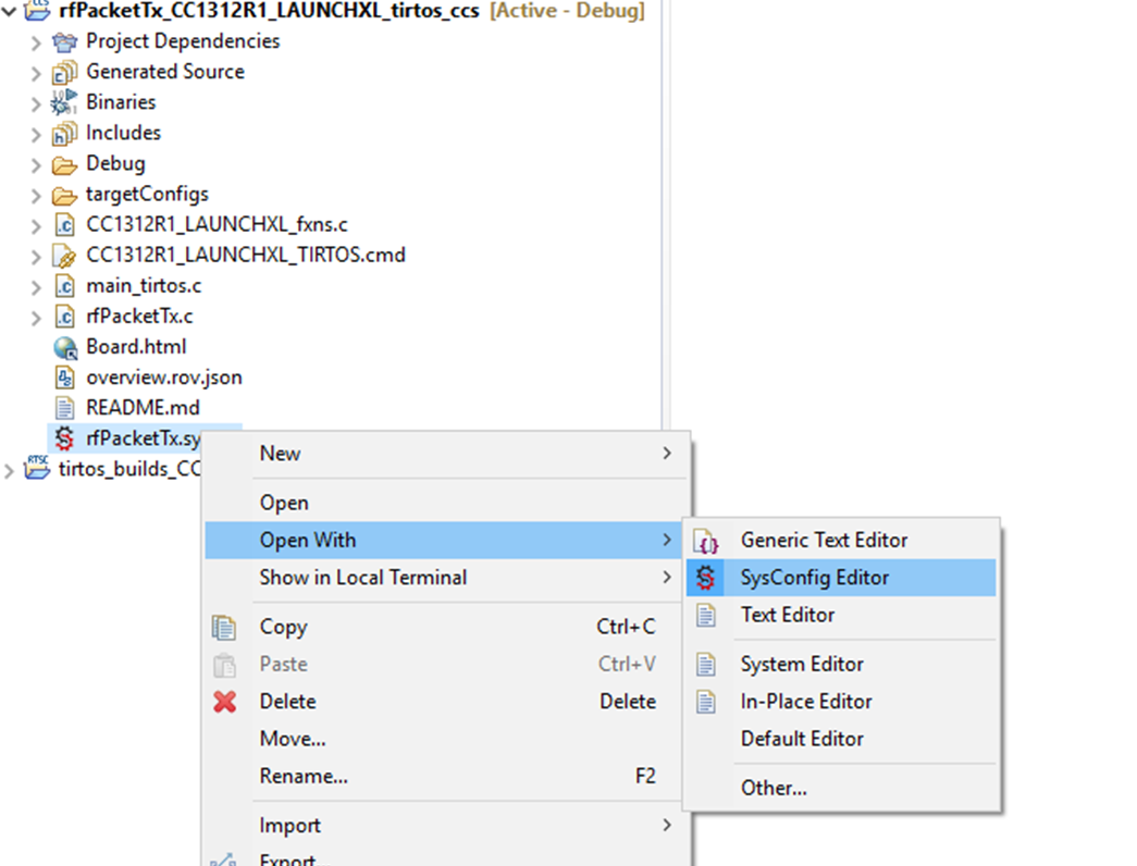
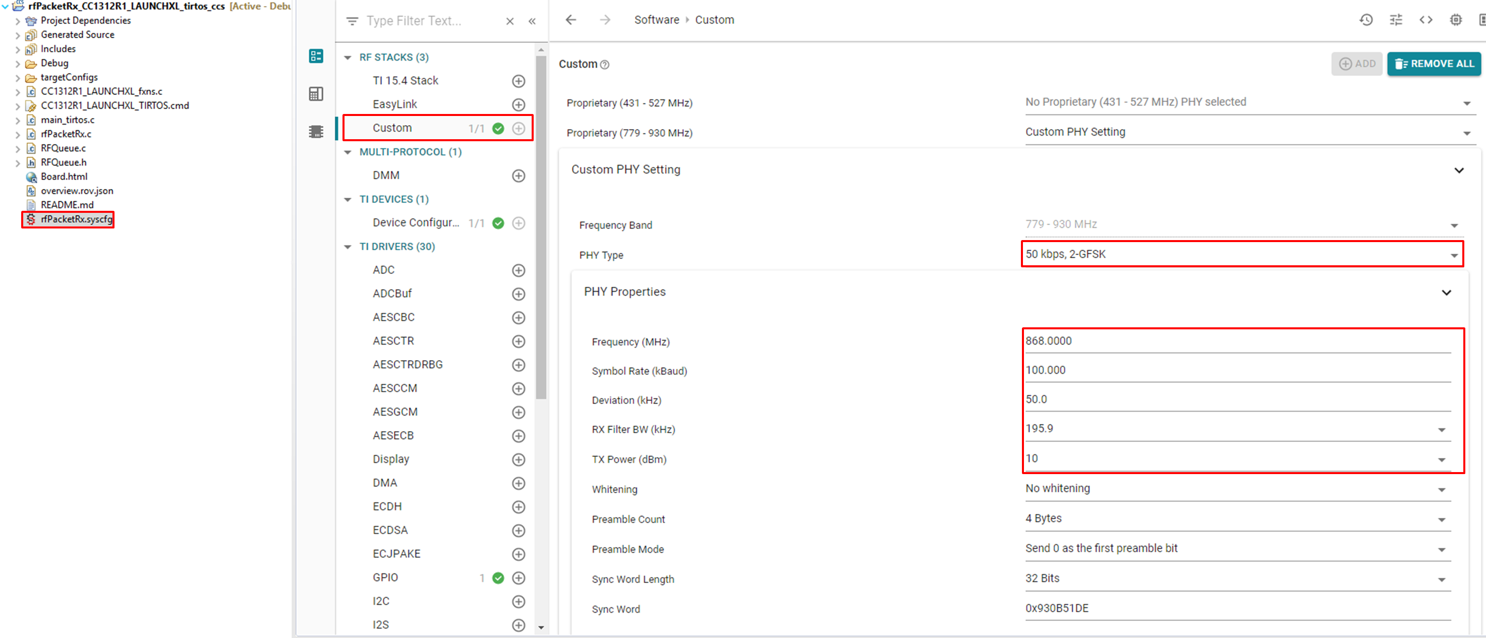
In CCS, in the corresponding project, open the *.syscfg file with SysConfig editor (here the file is named rfPacketTx.syscfg).
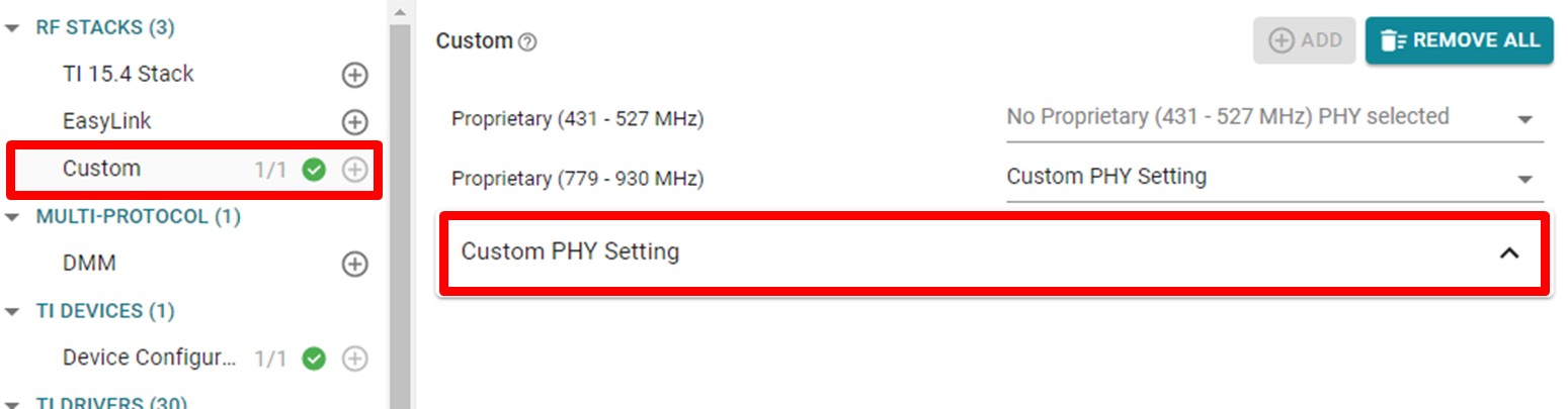
SysConfig opens in the main window. Here we want to modify the RF Stacks settings (here we are using the Custom RF Stacks). So click on Custom, then open the Custom PHY Setting interface by cliking it.
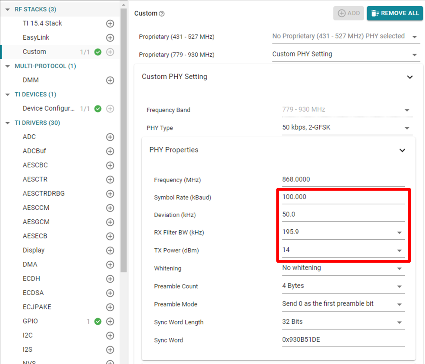
Now you can modify the PHY properties as follows:
- type in 100 in the Symbol Rate text box
- 50 in the Deviation text box
- choose 195.9 from the RX Filter BW drop down list
- choose 14 from the TX Power drop down list
I am getting a warning!
If the GUI is showing a warning as on the picture below, don't worry!
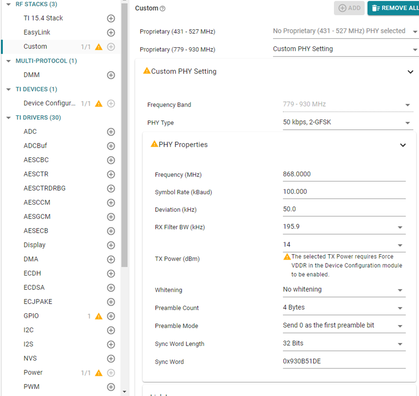
One solution is to basically ignore this warning and continue the lab. This will not prevent you to send out the packets. However, the TX power will not be 14 dBm as expected (but slightly lower).
Another solution (the right one) is to force VDDR. Still in SysConfig Editor, click on Device Configuration and check the box Force VDDR.
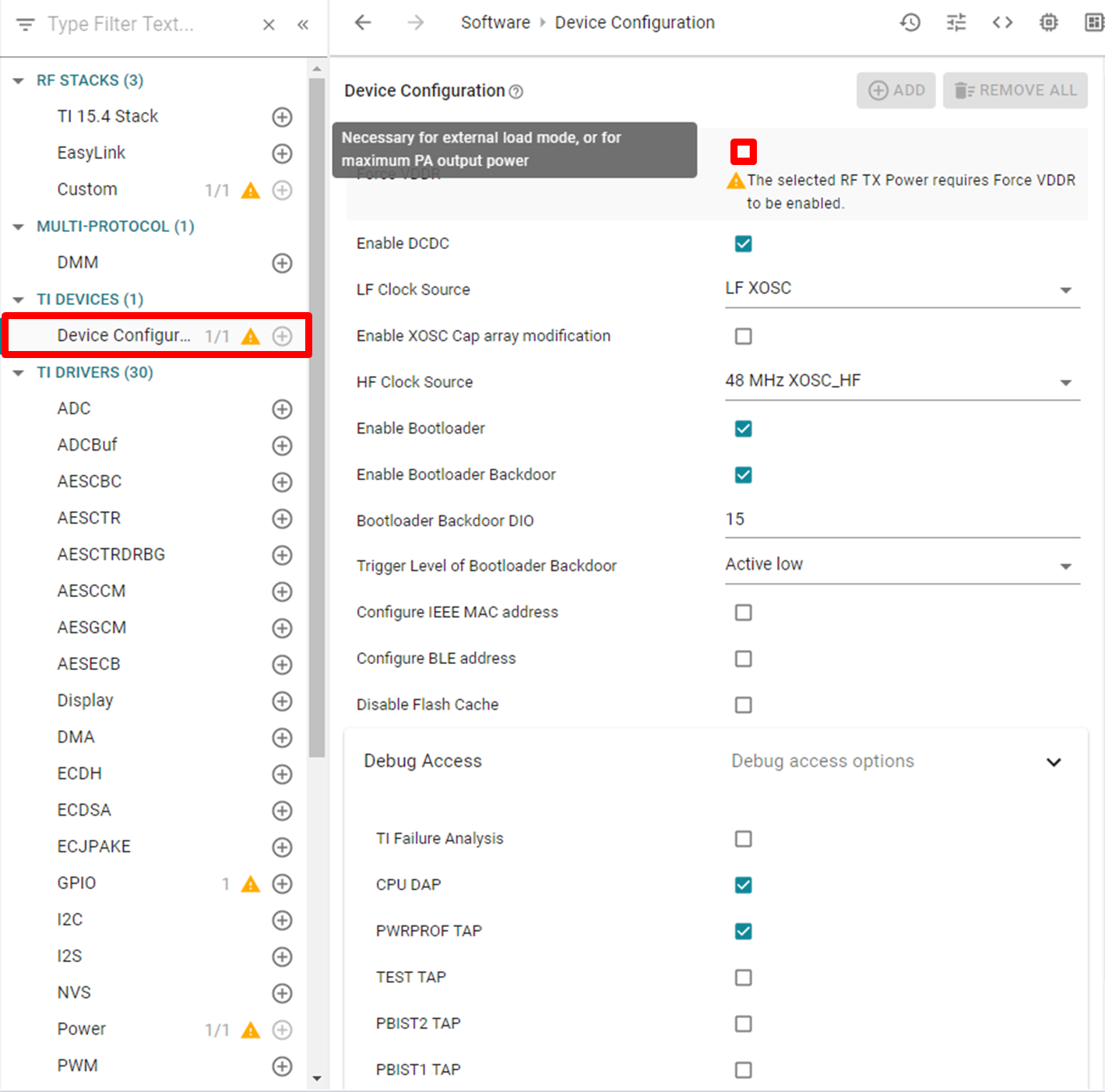
Note: Here you have basically forced VDDR to be 1.95 V (instead of 1.8 V). This will lead to an higher power consumption but it is necessary if you want to have TX Power = 14 dBm.
Now you are ready to test your application
Don't forget to save your changes, rebuild the project and download the image on the device.
SmartRF Studio can be used to generate radio operation commands to be used with the RF driver. This makes it easy to set-up PHY settings in SmartRF™ Studio and then export these exact settings to be used in your application.
By default, the rfPacketTx/Rx examples already contain such exported settings with the following values for the CC13xx device:
| Description | Value |
|---|---|
| Address | aa-bb |
| Frequency | 868.00000 MHz |
| Data Format | Serial mode disable |
| Deviation | 25.000 kHz |
| Packet Length Config | Variable |
| Max Packet Length | 128 |
| Packet Length | 30 |
| RX Filter BW | 98 kHz |
| Symbol Rate | 50.00000 kBaud |
| Sync Word Length | 32 Bits |
| TX Power | 14 dBm |
| Whitening | No whitening |
Follow the next steps to set the required configuration, export it and include it in the CCS project:
Open up SmartRF Studio. In the main window, right-click on the Chip icon corresponding to the device you are using and select Open RF Device in Offline Mode. Instead of right-clicking, you can also click the small white triangle inside the red circle. Select Proprietary mode.
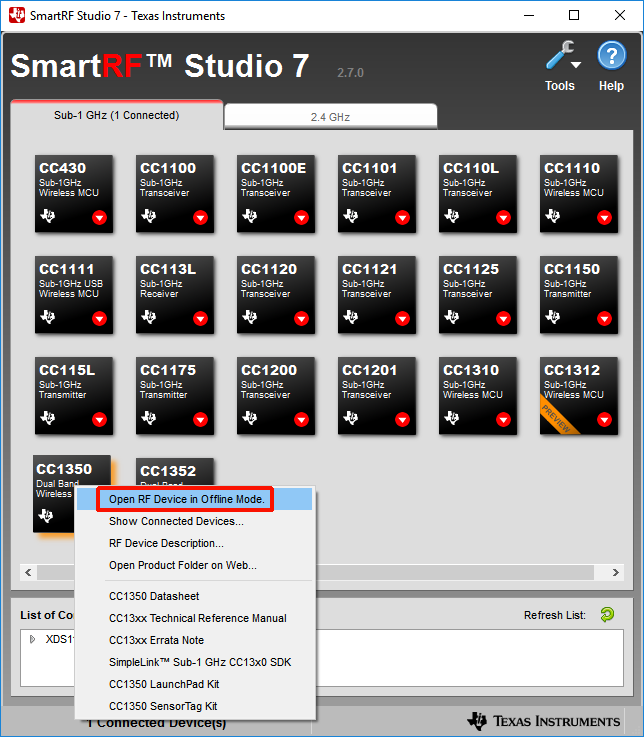
Offline Mode
Conveniently, it is possible to open the Device Control Panel without connecting to any physical device. This is perfect when exporting settings.
Enable the Command View by checking the Command View check box at the top of the Device Control Panel.
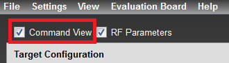
Command View
Once clicked Command View, note the new view on the right. This view lists all radio commands needed for setting up Packet RX / Packet TX (depending on the view you are in).
In the section Typical Settings, double-click on 50 kbps, 2-GFSK, 25 KHz deviation (or 100 kbps, 2-GFSK, 50 kHz deviation if using CC2640R2).
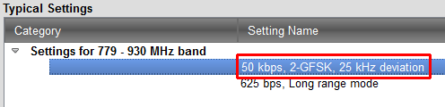
This is to ensure that you start with the recommended settings closest to the ones we are implementing in this task.
In the RF Parameters section, type in 100 in the Symbol Rate text box, 50 in the Deviation text box and choose 195.9 kHz from the RX Filter BW drop down list. If using the CC2640R2 lauchpads the value of the RF Parameters should be: 200 Symbol rate, 50 kHz Deviation and 530 kHz RX Filter BW.
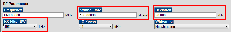
Change Frequency
If in a group, remember to change to your allocated frequency as described in the prerequisites section.
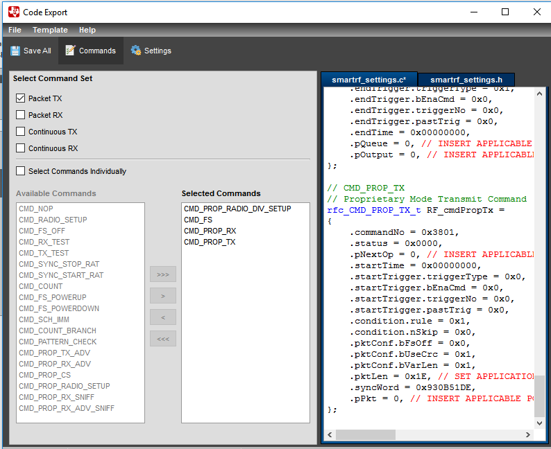
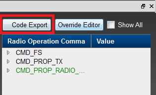
Click on the Code Export button at the top of the Command View:
In the newly opened Code Export window, click the Commands button in the middle.
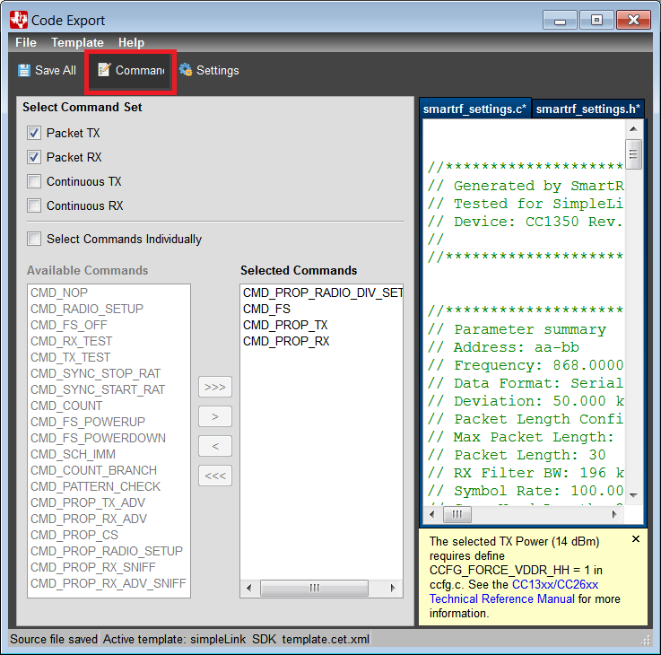
Code Export window - Selected Commands
This view shows which radio commands are going to be exported. By default, all commands needed for RX and TX are exported - these include the following commands, which are sufficient for this workshop:
- CMD_PROP_RADIO_DIV_SETUP (or CMD_PROP_RADIO_SETUP if exporting for CC2640R2)
- CMD_FS
- CMD_PROP_TX
- CMD_PROP_RX
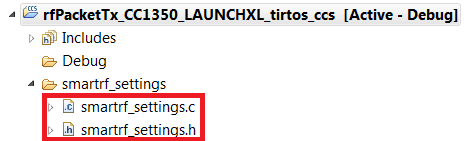
Two files are generated based on your settings in SmartRF Studio 7: smartrf_settings.c and smartrf_settings.h.
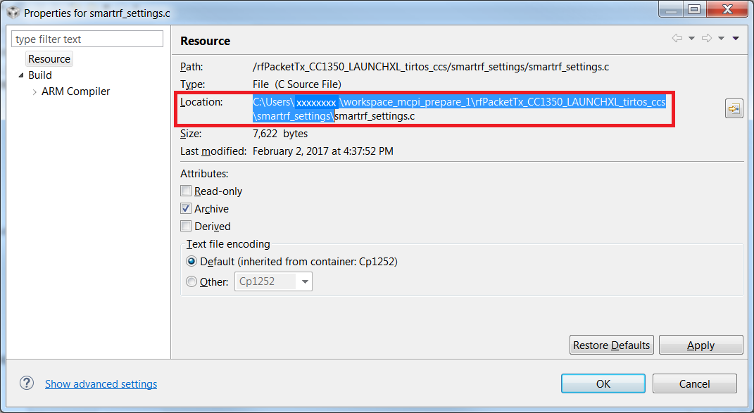
The rfPacketTx example already contains a version of these files. In CCS, find the folder location of these two files, by right-clicking one of them in the project explorer, then selecting Properties
In the properties window, look for the Location entry. Select the full path ( without the file name - see the image below), and copy it aside (e.g. to a notepad) - you will need it soon. Then click Cancel to close this window.
Delete the two existing files from the rfPacketTx project - click on each of these files in the project explorer and hit Delete):
Go back to the Code Export window of SmartRF Studio, select the smartrf_settings.h tab and press File → Save smartrf_settings.h As... Save this file into the same folder of the original smartrf_settings files (the path is probably still in your clipboard). Make sure to use the default file name (smartrf_settings.h)
Next, click on the smartrf_settings.c tab and press File → Save smartrf_settings.c As... Save it in the same folder as indicated above, using the default file name (smartrf_settings.c).
If you are using CC13X2 with SDK 3.30 (or newer)
The radio config is stored in the files
ti_radio_config.h/.c. As these files are generated at each build by SysConfig it is useless to modify the content of those files (your modification will be overwritten at each build). If you need to modify the files generated by SysConfig (to use the configuration files provided by SmartRF™ Studio for example), please follow the procedure described in the Proprietary RF User’s Guide in the SysConfig chapter.
Well done!
The PHY settings are now exported to CCS and your modified rfPacketTx example is ready to be built and debugged again.
Changes needed for CC2640R2
If using the CC2640R2 version of the example, a small modification has to be done to the smartrf_settings.c file before compiling.
Inside the smartrf_settings.c, locate the RF_cmdPropRadioSetup entry and change the name to RF_cmdPropRadioDivSetup.
Build and run the program on the "TX" LaunchPad.
Does it work?
Verify that the green LED (DIO7) toggles as expected.
Task 4 [optional]: Firmware TX → SmartRF Studio RX
In this task we will use SmartRF Studio to receive packets sent from the rfPacketTx application.
Complete the next steps to configure SmartRF Studio into RX mode, so that it can receive the packets sent by the rfPacketTX example.
Start up a SmartRF Studio instance and connect to the "RX" LaunchPad.
Set up SmartRF studio with the same settings used for TX:
In the section Typical Settings, double-click on 50 kbps, 2-GFSK, 25 KHz deviation (or 100 kbps, 2-GFSK, 50 kHz deviation if using CC2640R2).
This is to ensure that you start with the recommended settings closest to the ones we are implementing in this task.
In the RF Parameters section, type in 100 in the Symbol Rate text box, 50 in the Deviation text box and choose 195.9 kHz from the RX Filter BW drop down list. If using the CC2640R2 lauchpads the value of the RF Parameters should be: 200 Symbol rate, 50 kHz Deviation and 530 kHz RX Filter BW.
Change Frequency
If in a group, remember to change to your allocated frequency as described in the prerequisites section.
Don't forget to set the frequency
If you changed your frequency in the previous section, remember to do it now too
Go to the Packet RX tab and do the following:
- Change the Expected packet count by checking the Infinite check-box
- change Viewing format to Hexadecimal
Press the Start button.
What to expect
You should receive a message with the data generated by the rfPacketTx program every time the green LED (DIO7) toggles on the transmitting LaunchPad.
Task 5: Importing and Modifying rfPacketRx
In this task we will use CCS to import (as in Task 2), modify (as in Task 3) and build the rfPacketRx example.
The Packet RX example illustrates how to do simple packet RX using the TI-RTOS RF driver. This example is meant to be used with the Packet TX example or SmartRF Studio. For every packet received, the red LED (DI06) is toggled. The frequency and other RF settings can be modified using SysConfig or SmartRF™ Studio.
First, if there is an active debug session in CCS, please terminate it, e.g. by clicking the red square (Terminate) icon.
If SysConfig is already open, please close it.
If SmartRF Studio is currently connected to the "RX" LaunchPad, then please disconnect it (close the respective Device Control Panel window).
Repeat Task 2, but choose the example rfPacketRx and use the second LaunchPad - the one labeled "RX".
Why isn't the LED blinking?
Unlike the TX example, when running the RX example the green LED is not expected to toggle. When packets are received with CRC OK, the red LED will toggle, as you will see in the next task.
Now, modify the radio configuration using SysConfig. You have to basically chose the same configuration as the one you set in SmartRF™ Studio in Task 4. The procedure is the same that the one you used previously in Task 3:
Note: Here you don't need to modify the TX Power (as we will only RX)
Do not edit the configuration files
As the config files are generated at each build by SysConfig it is useless to modify the content of those files (your modification will be overwritten at each build). If you need to modify the files generated by SysConfig (to use the configuration files provided by SmartRF™ Studio for example), please follow the procedure described in the Proprietary RF User’s Guide in the SysConfig chapter.
To finish, save and close SysConfig. Then rebuild and run the rfPacketRx project on the "RX" LaunchPad.
First, if there is an active debug session in CCS, please terminate it, e.g. by clicking the red square (Terminate) icon.
If SmartRF Studio is currently connected to the "RX" LaunchPad, then please disconnect it (close the respective Device Control Panel window).
Repeat Task 2, but choose the example rfPacketRx and use the second LaunchPad - the one labeled "RX".
Why isn't the LED blinking?
Unlike the TX example, when running the RX example the green LED is not expected to toggle. When packets are received with CRC OK, the red LED will toggle, as you will see in the next task.
Copy the updated RF configuration files from the rfPacketTx project over the existing ones in the rfPacketRx project, by following these steps:
- In CCS' Project Explorer, locate the smartrf_settings.c/.h files in the rfPacktTx project, mark both files, right-click them and select "copy"
- Locate the smartrf_settings folder in the rfPacketRx project in project explorer, right click on it, and select "paste"
- In the pop-up windows that will open, click "Yes" to allow the files to be overwritten.
After updating the RF settings files, rebuild and run the rfPacketRx project on the "RX" LaunchPad.
Task 6 [optional]: SmartRF Studio TX → Firmware RX
Next we will send packets from SmartRF Studio and receive them with the firmware application.
Start up a SmartRF Studio instance and connect it to the "TX" LaunchPad.
Choose the same settings as before for the RF Parameters.
Go to the Packet TX tab and press Start
See it working
The red LED on the "RX" LaunchPad should now toggle for every packet being received with CRC OK. Note that when transmitting from SmartRF Studio, the green LED on the "TX" LaunchPad does not blink.
Task 7: Firmware TX → Firmware RX
In this task we will use the firmware on the two LaunchPads for communication between them: the "TX" LaunchPad will send packets, which will be received by the "RX" LaunchPad.
At this stage, the two LaunchPads should already have the respective firmware flashed. If this is not the case, re-flash them accordingly, as described in the previous tasks.
Stop all debugging (if currently active), disconnect any LaunchPad from the PC, and then reconnect them to the pc to power them up.
See it working
The green LED on the TX board should toggle, indicating packet transmission and the red LED on the RX board should toggle as packets are being received.
References
CC13xx Overview – Available here
CC2640R2 Overview – Available here
CC13x0 and CC2640R2 Technical Reference Manual – Available here
CC13x2 Technical Reference Manual – Available here
Proprietary RF User’s Guide – Available here
This work is licensed under a Creative Commons Attribution-NonCommercial-NoDerivatives 4.0 International License.