Introduction
This training will walk you through setting up the Wireless Sensor Network ( WSN) example. When you have completed the training you will have a WSN consisting of a concentrator displaying data received from one or more sensor nodes. The nodes will be truly ultra low power and only wake up to send data if the measured ADC value (capacitive coupling on certain pins) changes by a certain amount.
This tutorial will take about 1 hour to complete and requires little knowledge except some basic familiarity with embedded programming.
This tutorial does not include any (or little) programming, it is simply a step by step instruction on how to get one of the provided TI-RTOS SimpleLink getting started examples running in Code Composer Studio.
Technical support
For any questions you may have, please have a look at the relevant E2E forums: TI Sub-1 GHz E2E Forum, TI 2.4 GHz Proprietary E2E Forum
WSN Concentrator
The WSN Concentrator example illustrates how to create a simple WSN Concentrator device which listens for packets from other nodes. This example is meant to be used together with the WSN Node example to form a one-to-many network where the nodes send messages to the concentrator.
WSN Node
The WSN Node example illustrates how to create a WSN Node device which sends packets to a concentrator. This example is meant to be used together with the WSN concentrator example to form a many-to-one network where the nodes send messages to the concentrator.
Both the WSN concentrator and node example showcase the use of several Tasks, Semaphores and Events to get sensor updates and send packets with acknowledgment from the concentrator. For the radio layer, the examples use the EasyLink API which provides an easy-to-use API for the most frequently used radio operations.
Prerequisites
Allocated Frequency
If you are part of a group training, please ask the instructor for a unique frequency to use during this lab.
For simplicity, it is possible to use a base frequency (2440.0, 915.0, 868.0, 433.0), allocate a running number to each of the students and have each student multiply their number by 100 kHz channel spacing. For example, student #5 would then use 868 + 0.1*5 = 868.5 MHz.
Background
- Basic TI-RTOS and CCS knowledge.
- Read through the EasyLink layer chapter found inside the Proprietary RF User's Guide.
Software
In order to start with this exercise you will need to download the correct Software Development Kit (SDK) for your LaunchPad.
For CC13x0:
- SimpleLink CC13x0 SDK 3.10 or later.
For CC13x2:
- SimpleLink CC13x2 26x2 SDK 3.10 or later.
For CC2640R2:
- SimpleLink CC2640R2 SDK 3.10 or later.
Common software for all devices:
Code Composer Studio 9.0 or higher.
SmartRF™ Studio 2.12.0 or later.
Sensor Controller Studio 2.4.0 or later.
Hardware
- 2 x CC13x0 LaunchPads or 2 x CC13x2 LaunchPads or 2 x CC2640R2 LaunchPads
EasyLink API
The RF core has a dedicated driver called the TI-RTOS RF driver. This is used for all interaction with the RF core. The EasyLink API is a simple abstraction layer on top of the RF Driver and is intended as a starting point for customers creating a proprietary protocol or application using the Sub1-GHz or 2.4 GHz frequency band.
For instructions on using the CC13xx and CC2640R2 MCU SDK examples and the EasyLink API, refer to the Proprietary RF User's Guide.
EasyLink Examples
The following examples can be found in the resource explorer under the corresponding device SDK:
- rfEasyLinkTx
- rfEasyLinkRx
- rfEasyLinkEchoTx
- rfEasyLinkEchoRx
- rfEasyLinkNp
- rfEasyLinkListenBeforeTalk
- rfWsnConcentrator
- rfWsnConcentratorOadServer
- rfWsnNode
- rfWsnNodeExtFlashOadClient
- rfWsnNodeIntFlashOadClient
OAD = Over the Air Download.
Note
The EasyLink layer does not support any regional RF conformance such as Listen Before Talk required for the license free frequency band. Customers need to add support for the regional conformance that their product requires under the EasyLink API.
| Generic API function | Description |
|---|---|
| EasyLink_init() | Inits and opens the RF driver |
| EasyLink_transmit() | Blocking transmit |
| EasyLink_transmitAsync() | Nonblocking transmit |
| EasyLink_receive() | Blocking receive |
| EasyLink_receiveAsync() | Non-blocking receive |
| EasyLink_abort() | Aborts a non-blocking call |
| EasyLink_GetIeeeAddr() | Gets the IEEE address |
| EasyLink_EnableRxAddrFilter() | Enables/disables RX filtering on the address |
| EasyLink_SetFreq() | Sets the frequency |
| EasyLink_GetFreq() | Gets the frequency |
| EasyLink_SetRfPwr() | Sets the TX power |
| EasyLink_GetRfPwr() | Gets the TX power |
| EasyLink_getAbsTime() | Gets the absolute radio time |
| EasyLink_setCtrl() | Sets advanced configuration options |
| EasyLink_getCtrl() | Gets advanced configuration options |
Task 1: Importing the WSN Examples
In this task we will use Code Composer Studio (CCS) to import the WSN Concentrator example. The step-by-step guide is created from the perspective of using a CC13xx LaunchPad, if using a CC2640R2 LaunchPad the corresponding SDK should be selected instead of the CC13xx SDK that is used in the instructions.
Using IAR Embedded Workbench to import Examples
It is also possible to use IAR EW to import all MCU SDK examples. In order to do so follow the "Running examples in IAR" section of the Proprietary RF User's Guide
Importing and Building the RF Wireless Sensor Network Concentrator Example
Click on the drop down menu View → Resource Explorer
Note
Do not open Resource Explorer Classic (if it is an available option), in this task we will be working with the new Resource Explorer.
Expand the elements: Software → SimpleLink cc13xx SDK → Examples → Development Tools → CC13xx LaunchPad → EasyLink → rfWsnConcentrator → TI-RTOS → CCS Compiler
Select rfWsnConcentrator.
Your view should now be:
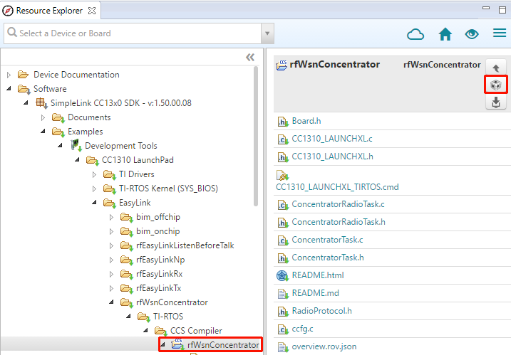
Click on the import icon in top right corner (shown in red box above).
There should now be a new project in the Project Explorer called rfWsnConcentrator_CCxxxx_LAUNCHXL_tirtos_ccs:
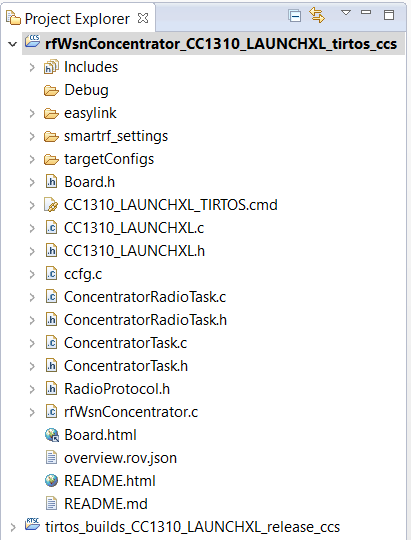
Note
The TIRTOS kernel is now included in a separate project imported with the example project. It can be seen above in the tirtos_builds_CCxxxx_LAUNCHXL_release_ccs project. The TIRTOS kernel project is specific to the Board type and compiler and shared by all examples for that Board type / compiler.
Connect one LaunchPad to your PC via USB. This will enumerate two serial COM ports on the PC, one of them will have the word "UART" in its name string - this is referred to as the Application UART.
Connect a PC terminal emulator program (e.g. Tera Term) to the LaunchPad via the Application UART port, using the configuration 115200,8,N,1.
Build and download the example by clicking "Debug" (shortcut F11):

Run the example by clicking on the play button.
You should now see "Waiting for nodes..." printed out to the terminal emulator.
Unplug your Concentrator device and continue with the tutorial.
Importing and Building the RF Wireless Sensor Network Node Example
Import the rfWsnNode examples as you did for the rfWsnConcentrator in the previous section.
Connect another LaunchPad to your PC via USB.
Several LaunchPads connected
In order to be certain you flash the right board, it is suggested that you disconnect the Concentrator board while flashing the Node board.
Build and download the example by clicking "Debug" (shortcut F11):
Run the example by clicking on the play button.
Task 2 – Putting it all to work
Power on your concentrator device
Power on your node device(s)
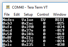
You shall now see data (raw ADC value) from all nodes connected to the concentrator being printed out to the terminal emulator connected to the concentrator once new data is received. Press and hold the left side button on the node device (marked BTN-1), the terminal emulator printout on the concentrator device should change from "0" to "1" under SW column.
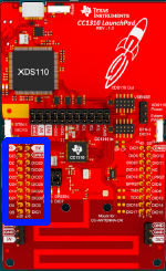
- The ADC is connected to the DIO26 pin on the node device. Cover the left
side pins with your finger (see pins marked in blue below) and observe a
change in node value on the concentrator device.
Task 3: Change RF Channel
In order to avoid interference form other devices on your joint training session it can be useful to change RF channel. Here is how you do it (remember to use a frequency that is supported by your device)!
Open the file "ConcentratorRadioTask.c" in your CCS editor.
Use the EasyLink_setFrequency API to change the frequency.
EasyLink_setFrequency(868300000);EasyLink_setFrequency used to select RF channel/frequency.
Build and download, make sure to make the changes on both your concentrator and node devices.
Task 4: Switch from Custom PHY to Long Range Mode (LRM)
Since the EasyLink layer supports different PHY settings it is straight forward to change the WSN example to use LRM instead. By default, the examples use settings exported from SmartRF Studio. In EasyLink, this is referred to as using a "custom phy". The default PHY settings is 2-GFSK 50 kbps (or 250 kbps for CC2640R2).
SimpleLink LRM is only supported by CC13xx devices
Currently, the is no LRM settings for the CC2640R2 device. If doing the lab using CC2640R2 LaunchPads, you can either skip this section or choose to use any of the other available 2.4 Ghz settings.
Open the file "RadioProtocol.h" in your CCS editor.
Change the RADIO_EASYLINK_MODULATION to your wanted setting.
#define RADIO_EASYLINK_MODULATION EasyLink_Phy_CustomRADIO_EASYLINK_MODULATION used to select RF PHY settings.
The EasyLink_Phy_Custom is a enum defined in EasyLink.h:
     //! \brief Phy Type passed to EasyLink_init()
 typedef enum
 {
     EasyLink_Phy_Custom = 0,           //!< Customer Phy specific settings exported from SmartRF Studio.
     EasyLink_Phy_50kbps2gfsk = 1,      //!< Phy settings for Sub1G 50kbps data rate, IEEE 802.15.4g GFSK.
     EasyLink_Phy_625bpsLrm = 2,        //!< Phy settings for Sub1G 625bps data rate, Long Range Mode.
     EasyLink_Phy_2_4_200kbps2gfsk = 3, //!< Phy settings for 2.4Ghz 200kbps data rate, IEEE 802.15.4g GFSK.
     EasyLink_Phy_5kbpsSlLr = 4,        //!< SimpleLink Long Range (5 kbps)
     EasyLink_Phy_2_4_100kbps2gfsk = 5, //!< Phy settings for 2.4Ghz 100kbps data rate, IEEE 802.15.4g GFSK.
     EasyLink_Phy_2_4_250kbps2gfsk = 6, //!< Phy settings for 2.4Ghz 250kbps data rate, IEEE 802.15.4g GFSK.
 } EasyLink_PhyType;
EasyLink_PhyType used to select RF PHY settings.
Build and download, be sure to make the changes on both your concentrator and node devices.
Task 5: Measure Power consumption on the node
The node is entering the lowest possible power mode between measurements - let's measure its average power consumption.
- Connect an ampere meter between pin3V3 and pinGND on your node device.
- Power on the node device.
Task 6: Modify Code Running on the Sensor Controller
The WSN node example includes code for the sensor controller, in this task we shall modify the interval for reading the ADC.
Make sure Sensor Controller Studio is installed on your system.
In your imported WSN node example, open the adc_sample.scp file from within Sensor Controller Studio by selecting "Open an existing project". The file is located in the sce folder.
Click on the execution code, in to pane to the right.
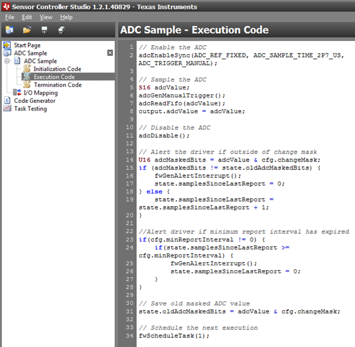
Modify the last line to:
fwScheduleTask(2);
...to make the next wake schedule every 2 tics.
Click on Code Generator in the right pane.
Click on the button on the bottom of the page saying "Generate driver source code":
Switch back to CCS, rebuild and run.
Measure average power consumption to see if is lower. We are now reading the sensor every 2 seconds instead of 1.
References
CC13xx Overview – Available here
CC2640R2 Overview – Available here
CC13x0 and CC2640R2 Technical Reference Manual – Available here
CC13x2 Technical Reference Manual – Available here
EasyLink API: Available in the Proprietary RF User's Guide
This work is licensed under a Creative Commons Attribution-NonCommercial-NoDerivatives 4.0 International License.