Introduction
This SimpleLink Academy lab introduces the reader to the fundamentals of DMM, and it is recommended to use this lab as a starting point for any DMM implementation done on a CC13x2 or CC26x2 device.
The Dynamic Multi-protocol Manager (DMM) allows multiple wireless stacks to coexist and operate concurrently on a single radio on a CC13x2 or CC26x2 device. DMM allows the user to define and control the priorities and timing constraints of each stack at run-time.
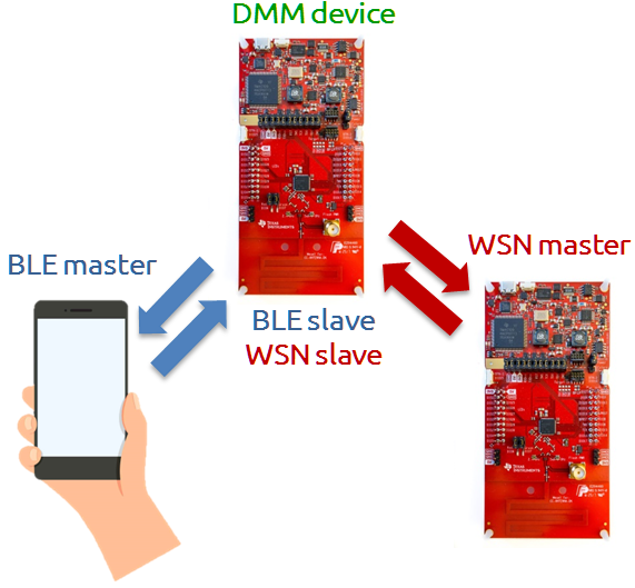
This lab will show how to use a single device as an EasyLink Wireless Sensor Network (WSN) Node on a sub-1 GHz radio frequency (RF) network while simultaneously acting as a BLE peripheral.
It is assumed that the user has previous knowledge of the Bluetooth® Low Energy (BLE) protocol and the EasyLink WSN Node and Concentrator topology. You can learn about this in the BLE and Proprietary RF SimpleLink Academy labs.
Additional examples
This lab focus on explaining the fundamentals of using DMM, which is why the DMM example with BLE Peripheral and EasyLink is used. DMM is not limited to this combination. There are other DMM examples in the SimpleLink CC13x2 / CC26x2 SDK with different wireless stack combinations, such as a TI 15.4 Sensor or ZigBee End Device with a BLE Peripheral.
For more information on available combinations and limitations, please refer to the DMM User's Guide.
Prerequisites
Other SimpleLink Academy Labs
- Completion of BLE Fundamentals
- Completion of BLE Connections
- Completion of Proprietary RF Wireless Sensor Network example
Hardware
For the DMM device, 1x LaunchPad of either:
For the WSN Concentrator device, 1x LaunchPad of either:
A smartphone with a BLE explorer app
Note
Depending on which LaunchPad is used as the DMM device, the antenna will be tuned for different frequency bands. This is also reflected in the EasyLink examples for that the LaunchPad in question.
For the WSN Node to be able to communicate with the collector, the two devices must have compatible settings. If using the same LaunchPad version for both the WSN Node and WSN Collector, the examples will have matching settings per default.
Software
- Code Composer Studio version 9.2 or later with support for CC13xx/CC26xx devices installed
- SimpleLink CC13x2 / CC26x2 SDK, version 3.30 or later
- If the WSN Concentrator device is a CC1310 or CC1350, then
- SimpleLink CC13x0 SDK, version 3.20 or later
Recommended reading
It is recommended to read the DMM User's Guide alongside this lab for details and further information.
Before you start
Attention
The steps in this lab make reference to CC1352R1 LaunchPad. Please note that the same steps apply when using either boards listed under required hardware.
Install the SimpleLink CC13x2/CC26x2 SDK.
Install Code Composer Studio. These instructions assume that you install CCS with support for the CC13xx and CC26xx devices.
Setup CCS Workspace
Before we start, create an empty CCS workspace and import the following example projects:
dmm_wsnnode_remote_display_app, found under<SDK>/examples/rtos/<BOARD>/dmm/.rfWsnConcentrator, found under<SDK>/examples/rtos/<BOARD>/easylink/.
where <SDK> is the install location of the SimpleLink SDK, and <BOARD> must
correspond to the board being used for that example project.
To import an example from the SimpleLink SDK, follow these steps within your workspace in Code Composer Studio:
Select
Project→Import CCS Projects...to open the import dialog.Browse to the path of the example as the search directory. Click
Select Folder.Select the example project, and click
Finishto import the example application.Repeat the process for the other example project.
When both projects has been imported, build them by doing one the following:
Right clicking on the project in the project explorer and selecting
Build Project.Clicking
Project→Build Project.Clicking the hammer icon.
Ctrl + B.
Make sure both projects builds successfully.
Project README
You can refer to the project's README file for a functional description of each example.
Group Training – Additional Requirements
If you are working in groups, make sure to always use your designated frequency to avoid interfering with other operations. Also, change the BLE scan response to output a uniquely identifiable name.
Feel free to skip this section if you are not participating in a group training.
Frequency Allocation
In order to avoid interfering with other groups when operating on the same frequency, use a unique frequency during this lab.
Ask your Instructor
If you are part of a group training, please ask the instructor for a base frequency and a unique number to generate your unique frequency to use during this lab.
For simplicity, it is possible to select a base frequency (915.0 MHz, 868.0
MHz, 433.0 MHz), allocate a running number to each of the operators and
have each operator multiply their number with a 100 kHz channel spacing. For
example with using base frequency 868.0 MHz, group #5 would use the
following frequency 868 + 0.1 * 5 = 868.5 MHz.
The frequency is configured in both examples with SysConfig as such:
Open SysConfig by double clicking on the
*.syscfgfile.dmm_wsnnode_remote_display.syscfgfordmm_wsnnode_remote_display_app.rfWsnConcentrator.syscfgforrfWsnConcentrator.
In SysConfig, navigate to
EasyLink→Custom Radio Settings→PHY Properties→Frequency (MHz).Change the value of
Frequency (MHz)to the unique frequency.
BLE Scan Response
To make it easier for the operators to distinguish between the BLE advertisements, it is recommended to change the BLE scan response to output a unique identifiable name.
Ask your Instructor
If you are part of a group training, please ask the instructor for a unique number to use in your scan response during this lab.
The BLE scan response is configured in dmm_wsnnode_remote_display_app with
SysConfig as such:
Open SysConfig by double clicking on the
dmm_wsnnode_remote_display.syscfgfile.In SysConfig, navigate to
BLE→Broadcaster Configuration→Advertisement Set 1→Scan Response Data 1→Complete Local Name.Change the value of
Complete Local Nameto the unique identifiable name.
Dynamic Multi-protocol Manager (DMM)
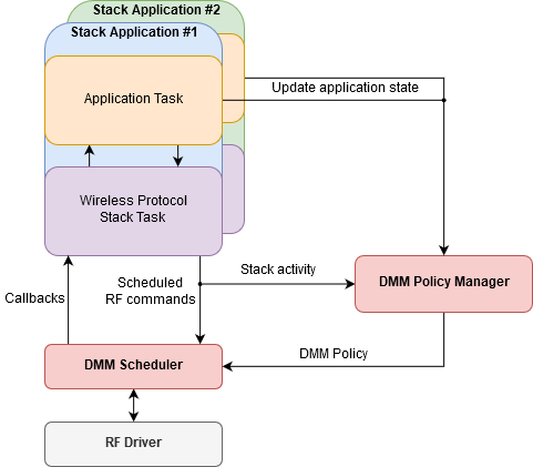
DMM is a layer between the RF protocol stacks and the RF Driver. It will intercept calls to the RF driver done from either a protocol stack or an application, and will modify the order in which RF commands are scheduled based on constraints and requirements from the applications and stacks. For a full description of DMM, please refer to the DMM User's Guide.
DMM consists of two modules:
- The DMM Policy Manager – determines the current DMM policy from the DMM policy table, based on the current combination of stack states and stack activities as reported by the applications and protocol stacks, respectively.
- The DMM Scheduler – manages scheduled RF commands, resolves conflicts during a schedule and interfaces the RF driver.
A block diagram of DMM in relation to the stack applications and the RF driver is given in the following figure:
DMM is configured in SysConfig under the Multi-Protocol section. Below is an overview of that configuration page.
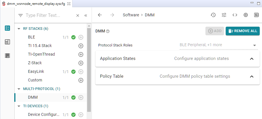
Protocol stack roles are unique IDs assigned to each stack application, and is used to identify which stack application is updating its application state to DMM. Each stack application has a set of one or more application states, and is configurable by the developer.
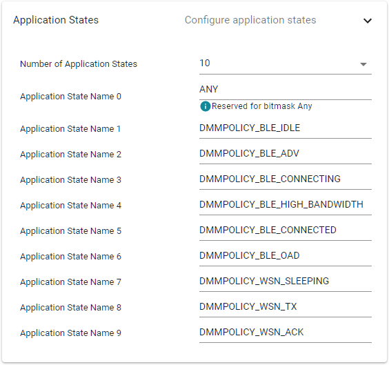
In the case of the dmm_wsnnode_remote_display_app example, a set of
application states has already been defined for both the BLE and WSN
application. Note the special application state ANY, which is used to match
any application state when making a DMM policy.
The current application state of both stack applications results in an active DMM policy from the DMM policy table. A DMM policy is scheduling rule for both stack application, and the DMM policy table makes up the complete set these scheduling rules used in the system. This is explained in more detail later.
Quiz
How does DMM know what application state the BLE peripheral application is in?
DMM Policy Manager
The primary goal of the DMM policy manager is to determine which stack application has priority over the other at any given time. This is used by the DMM scheduler when a protocol stack schedules an RF command which creates a conclict with a different protocol stack.
In order to determine which stack application has priority over the other, the DMM policy manager keeps track of the current DMM policy, combined with scheduled RF activities. A DMM policy decides the scheduling rules both protocol stacks, and in the end determines which protocol stack has priority over the other. The complete set of all DMM policies used in the system are stored in the DMM policy table.
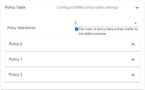
DMM Policy Table Order
The order of policy table entries matter, since the search of the active DMM policy are done in ascending order and will return on the first match.
Priorities are set by the Global Priority Table (GPT). GPT defines the base priority for all stack activities. It is this base priority, combined with the weight from the active DMM Policy, that determines which stack has priority over the other for a given stack activity.
GPT is not configured in SysConfig. TI provides pre-made GPTs in the SDK,
found under <SDK>/source/ti/dmm/. These GPTs are named
dmm_priority_{stacks}.h, and serves as a starting point with tested default
values. Please refer to the source code for more documentation and overview of
each GPT.
Priority Tiebreaker
The GPT and DMM policy table should be designed to avoid ties; how else are you supposed to decide who has priority?
In the unlikely event of a tiebreaker, the last DMM policy entry in the policy table, also known as the default policy, acts as a tiebreaker. The stack with the higher priority in that policy wins.
A DMM policy tells the scheduler which stack has priority in a certain application state and whether submitted RF commands can be deferred or not. From the policy, the scheduler can deduce how a scheduling conflicts shall be resolved. Each policy within the structure represents a comprehensive system state for each stack application and consists of the following parameters:
- Weight – an application weight where a higher value represents a higher priority
- Paused Stack – callback notification if the stack application must pause or resume the radio activity
- Application States – one or more application states for which this policy is valid for
- Applied Activity – none or more stack activities for which this policy applies to
Below is a DMM policy from the dmm_wsnnode_remote_display_app, which
configures the following:
- BLE Peripheral application
- must be in the BLE OAD application state; and
- no particular stack activity; which
- gives weight of 0; and
- no pause requirements
- WSN Node application
- can be in Any application state; and
- no particular stack activity; which
- gives weight of 0; and
- radio activity must be paused
This DMM policy could be described in words as such: when the BLE application is in some OAD operation, regardless of what radio activity, and the WSN Node is in whatever state and radio activity, they both have equal weight, but the WSN Node application must pause its radio activity.
In SysConfig, the same DMM policy would be configured as such:
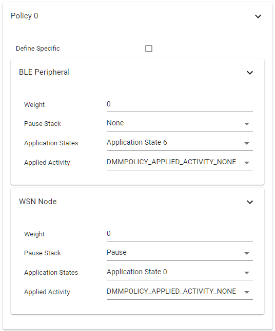
Application State Names
There is currently a limitation in SysConfig which does not allow displaying the name of all application states; they will only show as Application State #. Refer to the Application States overview in SysConfig for which application states you have defined.
Applications use the DMMPolicy_updateStackState() API to notify DMM of an
application state change, which takes a protocol stack role and the new
application state as arguments. Calling this functions multiple times in a row
with the same arguments will not change the active DMM policy, it will only
cause unecessary overhead and is generally recommended to avoid.
Quiz
Study the DMM policy table in SysConfig. Which of the following statements are true?
DMM Scheduler
As illustrated in the DMM block diagram, the DMM Scheduler handles all interactions with the RF driver. A core concept of DMM is that the wireless protocol stack does not need to be directly aware that DMM is present. In other words, it should be able to operate as normal whether it running in a DMM application or not.
RF Driver Concepts
To fully understand the DMM scheduler you need to understand how the RF driver operates with RF commands and the internal RF command queue. This can be read in more detail in the Proprietary RF User's Guide.
When a wireless protocol stack submits an RF command, the RF driver will invoke the scheduler function supplied by the DMM to schedule the command. The scheduled RF driver The DMM Scheduler acts according to the following criteria:
- What are the current stack priorities?
- What are the timing constraints of the scheduled RF command?
- Are there any commands in the RF queue, and what priority do they have?
At first, the DMM scheduler will try to simply schedule the new command directly based on its start time. If the DMM scheduler is not able to schedule the command due to a conflict with another stack, it will try to resolve the conflict using the current stack priority and timing constraints.
In the case where it is time to run the next command in the RF command queue, but the radio is still busy with the previous command, the RF driver will invoke to the DMM conflict resolution function to resolve the run-time conflict.
In order for DMM to inject itself in-between the wireless protocol stacks and the RF driver without directly changing the RF driver API calls, some RF Driver API functions are re-mapped to the equivalent DMM function. In both the BLE Peripheral and WSN Node stack, the DMM RF map header file is included instead of the RF driver when DMM is used.
#ifndef USE_DMM
#include <ti/drivers/rf/RF.h>
#else
#include <dmm/dmm_rfmap.h>
#endif //USE_DMM
rd_ble_user_config.c – the RF driver remapping to DMM is included instead of the RF driver when USE_DMM is defined
Note that the define USE_DMM is used as a feature flag to differentiate
between a DMM and non-DMM application. If you take a look at the file
dmm/dmm_rfmap.h you can see which RF driver functions that are redefined.
Quiz
Which of the following statements is the expected behavior for the DMM Scheduler?
Task 1 – Setup the DMM Device
The first task is to setup the DMM example application on the DMM device.
Build the DMM example (
dmm_wsnnode_remote_display_app) by doing one of the following:Right clicking on the project in the project explorer and selecting
Build
Project
Clicking
Project→Build ProjectClicking the hammer icon
Ctrl + B
Debug the DMM example by doing one of the following:
Right clicking on the project in the project explorer and selecting
Debug As→Code Composer Studio Debug SessionClicking
Run→DebugClicking the green bug icon
F11
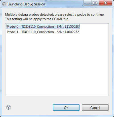
If you have multiple debug probes are connected to your computer, CCS will prompt you to select one. This serial number will be set as the debug connection for this target configuration.
Once the debug session has flashed the device, the debugging session should halt a
main(). Allow the example application to free run by:Clicking
Run→ResumeClicking the green resume button
F8
End the debugging session by clicking the red stop button.
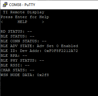
Connect a terminal program to see the serial output from the device. This is described in the BLE Fundamentals SimpleLink Academy lab. When you press play, the device will output the following:
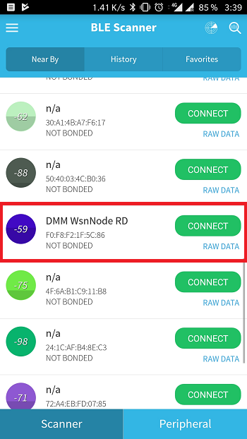
Verify the device is advertising over BLE with a smartphone. Steps for connecting to a smartphone are given in the BLE Fundamentals SimpleLink Academy lab.
The device will either advertise with the default name "DMM WSNNode RD" as seen below, or using the name chosen following the group training recommendations.
DMM Device is now setup
You now have a device that is concurrently running as a WSN Node and as a BLE Peripheral.
Task 2 – Setup the WSN Concentrator
The DMM device is a WSN Node. We need a WSN Concentrator to connect to it in order to see the Sub-1 GHz network. Setting up a WSN Concentrator is described in the SimpleLink Academy module Proprietary RF Wireless Sensor Network Example.
When you start the WSN Concentrator, the node will connect to it automatically. You may have noticed that the WSN Node outputs a counter, called "WSN Node Data". You can now see that this information is transmitted to the concentrator.
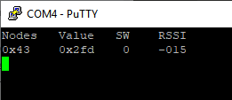
We now have two devices connected to the DMM device over two different RF protocols. With your phone, you can use the Remote Display Service to interact with the WSN network.
Interacting with the node and concentrator over BLE
While connected to the WSN Node over BLE it is possible to interact with
both the WSN Node and WSN Concentrator (via the WSN Node). Information on
how to interact with the WSN network is found inside the
dmm_wsnnode_remote_display_app README.
Limitations
Unlike Task scheduling in TI-RTOS, RF scheduling cannot be preempted and resumed at a later time. Instead, DMM will use the policy table to resolve scheduling conflicts between the stacks. Whenever there is a scheduling conflict, DMM will either reject the new command or abort the conflicting command in favor of the new command. This means that there are limitations to which DMM use-cases that are feasible.
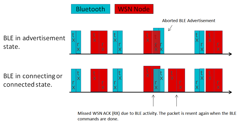
When looking at the policy table, we can see that when the BLE Peripheral is in advertisement mode, the WSN Node has a higher priority than the BLE Peripheral. However, when the BLE Peripheral is in any other state then advertising, the priorities are inverted, giving the BLE Peripheral higher priority than the WSN Node.
In this example, the BLE Peripheral is set to advertise at a 100ms interval while the WSN Node is set to transmit a packet every second. This means that for most of the time there will be no scheduling conflicts, and if one was to arise the WSN Node would have higher priority. In theory, assuming ideal conditions, the WSN Concentrator would never miss a WSN Node packet while the BLE Peripheral is in advertising mode.
Connecting to the BLE Peripheral will not only change the priority, but also potentially increase the BLE activity depending on the negotiated interval. You can read about the connection interval negotiation in the BLE connection lab. This means that when connecting to the BLE Peripheral, we are more likely to observe missed packages due to BLE scheduling interference.
This is illustrated in the packet diagram below where the aborted packets are in the background of the higher priority one.
Quiz
Which of the following aspects are important in the context of DMM when considering running two stack applications?
Task 3 – Enable Statistics
Let us setup our DMM project to observe some WSN Node statistics! The WSN Node application already keeps track of some statistics, but we need to enable the printouts of these statistics. We do this by doing the following:
Navigate to
Project Properties→Build→ARM Compiler→Predefined Symbols.Add the define
RD_DISPLAY_WSN_STATS.Build project and flash the DMM device.
While already tracking some statistics, the WSN Node does not track the number of aborted command per default. We will need to modify the WSN Node application to also count the numbers of aborted packages.
Inside NodeRadioTask.c, found under application/wsn_node/, navigate to the
rxDoneCallback() function and add another check to handle aborted commands.
/* did the Rx timeout */
else if(status == EasyLink_Status_Rx_Timeout)
{
    /* Post a RADIO_EVENT_ACK_TIMEOUT event */
    Event_post(radioOperationEventHandle, RADIO_EVENT_ACK_TIMEOUT);

    radioStats.ackRxTimeout++;
    RemoteDisplay_updateNodeWsnStats(&radioStats);
}
// =========== ADD START ===========
else if (status == EasyLink_Status_Aborted)
{
    /* Count number of aborted packages */
    radioStats.ackRxAbort++;
    Event_post(radioOperationEventHandle, RADIO_EVENT_ACK_TIMEOUT);
}
// =========== ADD END ===========
else
{
    /* The Ack reception may have been corrupted causing an error.
     * Treat this as a timeout
     */
    Event_post(radioOperationEventHandle, RADIO_EVENT_ACK_TIMEOUT);
    rxErrorFlg |= status;
    radioStats.ackRxSchError++;
    RemoteDisplay_updateNodeWsnStats(&radioStats);
}
NodeRadioTask.c – rxDoneCallback()
Abort Status for EasyLink
EasyLink_Status_Aborted is the EasyLink stack return status received
when the RF driver reports a command as stopped or aborted. The WSN Node
application is built on top of the EasyLink stack.
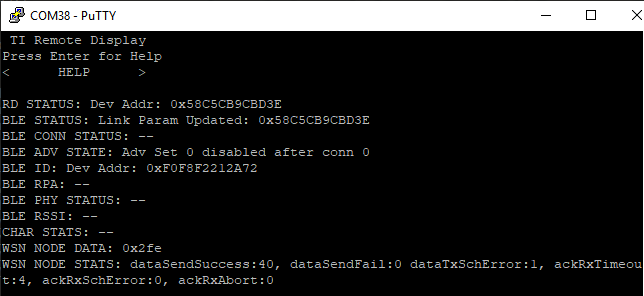
Build and download the changed project to the DMM device. When pressing play, the terminal output from the device should look something like this:
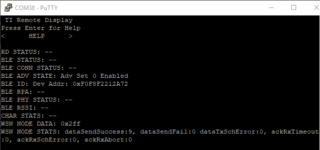
While the BLE Peripheral is running in advertising mode, you should not see
any missed packages. It is also worth comparing the ackRxTimeout and
dataSendSuccess values, these can be mapped to how well the connection is
working.
Ideally, there would be no timeout or scheduling errors as this means that
either the WSN Node missed an ACK from the WSN Concentrator, or that the WSN
Node was not able to schedule an RX or TX command. When missing an ack from
the collector, the WSN Node will try to re-transmit the packet a specific
number of times before it is counted as a dataSendFail. The number of
retries the WSN node will perform is defined by
NODERADIO_MAX_RETRIES inside NodeRadioTask.c. Now
connect to the BLE Peripheral using your smartphone and observe how the the
statisics change:
As we can see in the picture, most node packages are still counted as
"successful" even while the ackRxTimeout counter increases due to the
WSN Node ACK timeout. We can also see that there is no ackRxAbort count,
meaning the DMM is not aborting any of the WSN Node's commands. They are
simply postponed and will later timeout when the WSN Concentrator's ACK is
missed.
Furthermore, it can be seen that since connecting to the BLE peripheral, the
DMM Scheduler sometimes reject the WSN Node when it tries to schedule the
sensor data packet by observing the dataTxSchError value.
Messing With The Timings
Now, let us see what happens if we change the WSN Node timings to seriously
interfere with the BLE Peripheral timings. Inside NodeRadioTask.c, the
WSN Node RX timeout noRadioAckTimeoutTimeMs is set at the beginning of the
nodeRadioTaskFunction() function. noRadioAckTimeoutTimeMs sets the RX
timeout the WSN Node uses when listening for a ACK from the WSN Concentrator.
Change the value of noRadioAckTimeoutTimeMs used for the
EasyLink_PHY_CUSTOM case from 10ms to 350ms. This means that the RX command
for sure will overlap with at least one BLE advertisement packages as the
advertisement interval for the BLE Peripheral is 100ms.
uint32_t noRadioAckTimeoutTimeMs;
if (RADIO_EASYLINK_MODULATION == EasyLink_PHY_CUSTOM)
{
    //noRadioAckTimeoutTimeMs = 10;
    noRadioAckTimeoutTimeMs = 350;
}
else if (RADIO_EASYLINK_MODULATION == EasyLink_PHY_5KBPSSLLR)
{
    noRadioAckTimeoutTimeMs = 100;
}
else
{
    System_abort("Unsupported PHY Mode.");
}
NodeRadioTask.c – nodeRadioTaskFunction()
Build and download the changed project to the DMM device and again observe the WSN node statistics.
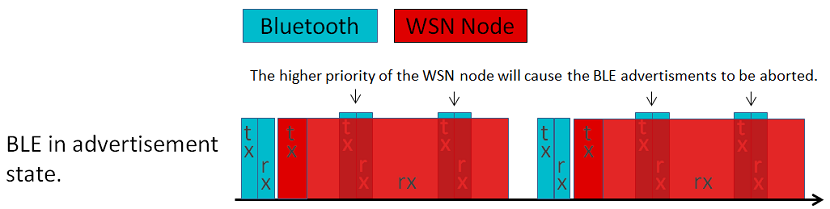
While the BLE Peripheral is running in advertising mode there is no difference in the WSN Node statistics. However, due to the longer RX timeout for the WSN Node command, no BLE advertisements will be able to run for the full length of the specified RX timeout. This is illustrated in the picture below, where the blue background commands is the aborted BLE advertisement commands.
Note that due to the long intervals between the actual WSN Node packages, the BLE Peripheral will still be able to advertise often enough that it will be discoverable by the phone. If trying to connect to the device, you should see that this is still possible.
Dead time
The new RX timeout in the WSN Node does not necessarily mean that the WSN Node will stay in RX for this amount of time. In the worst case, the WSN Node does not receive the ACK and thus stays in RX for the full RX timeout time..
If the ACK is received before the RX timeout occur, the WSN Node will stop receiving and a previous aborted command can be re-scheduled even if this initially conflicted with the WSN Node RX command.
Now, disconnect your WSN Concentrator device to force the WSN Node to
experience RX timeouts. You should now see that the DMM device is unable to
send any data messages to the WSN Concentrator, and the dataSendFail
statisic increases. However, the BLE connection with the phone is still able
to be maintained.
One would believe that when the WSN Node tries to re-transmit the packet two times, the WSN Node would block the radio for a total amount of time of ~1050ms, or three RX timeouts per unique packet it tries to send. However, connection events from the BLE Peripheral will preempt the ongoing RX in the WSN Node, and will make sure the BLE connection is not broken.
Congratulations!
You have successfully tested a use-case where DMM preempts an on-going operation in order to maintain a BLE connection. If you want to know how to DMM-enable a standalone project, continue doing the bonus Task 4.
Task 4 (bonus) – Create a DMM Application from scratch
In this bonus task we will create a DMM application from scratch by taking a single RF stack example, enable DMM and add a second RF stack. For this example we will create a Bluetooth Peripheral and WSN Node application with Project Zero as the starting point.
Import and Build Project Zero
Start with importing the Project Zero project into your workspace. This project will form the foundation for our DMM project, where we later are going to add the WSN Node application.
Refer to the Build the projects and Flash the device section of the BLE Fundamentals SimpleLink Academy lab for steps on how to import, build and flash the device.
Adding DMM to Project Zero
First step is to convert the Project Zero project to use the DMM.
Restructure the CCS project
Start by organizing the folders to better fit a DMM project:
Add a new folder called
project_zero/inside theApplication/folder, and move the contents of the application folder inside this new folder.Create a new top-level folder called
dmm/.
Now add the DMM header files to the newly created dmm/ folder. Copy the
following files from the SDK, found under <SDK>/source/ti/dmm/, into your
workspace:
dmm_rfmap.hdmm_scheduler.hdmm_policy.hdmm_priority_ble_wsn.cdmm_priority_ble_wsn.h
DMM Pre-defined Priority Tables
The SDK already provides pre-defined priority tables for certain
combination of RF stacks. In this case of BLE + WSN, the priority table
dmm_priority_ble_wsn is available.
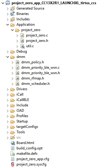
Your project explorer should look something like this:
The define USE_DMM is used as a feature flag to indicate that DMM is used.
It is important we set this define in order for TI source code to know to use
DMM.
Navigate to
Project Properties→Build→ARM Compiler→Predefined Symbols.Add the following pre-define:
USE_DMM
In order for the project to find the recently added files, add the following include search paths in the project properties:
Navigate to
Project Properties→Build→ARM Compiler→Include Options.Add the following search paths:
${PROJECT_ROOT}/Application/project_zero${PROJECT_ROOT}/dmm
The pre-compiled DMM library also needs to be included as part of the linker step:
Navigate to
Project Properties→Build→ARM Linker→File Search Path.Add the pre-compiled DMM library at the top in the Include library file view:
If you are compiling for a CC13x2 device:
${COM_TI_SIMPLELINK_CC13X2_26X2_SDK_INSTALL_DIR}/source/ti/dmm/library/tirtos/ccs/bin/dmmlib_cc13x2.a
If you are compiling for a CC26x2 device:
${COM_TI_SIMPLELINK_CC13X2_26X2_SDK_INSTALL_DIR}/source/ti/dmm/library/tirtos/ccs/bin/dmmlib_cc26x2.a
Add DMM in SysConfig
Next step is to add DMM in SysConfig, which allows us to configure a DMM
policy table. Open SysConfig by double clicking on the project_zero.syscfg
file. In the SysConfig view, add DMM by simply clicking on the pluss sign next
to the DMM section.
SysConfig Warning
Immediately after adding DMM you will get a warning. We will fix this very soon.
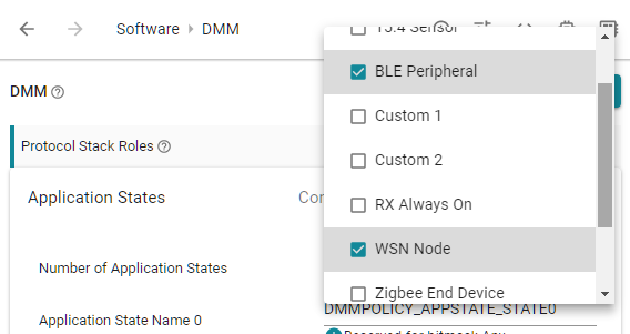
In the DMM section, the Protocol Stack Roles are by default set to Custom 1
and Custom 2. It is fine to let these be as is, as they are just names.
However, for the sake of clarity in this task, we will change these to BLE
Peripheral and WSN Node.
Click on the drop down next to the Protocol Stack Roles and deselect the
currently selected roles and select BLE Peripheral and WSN Node.
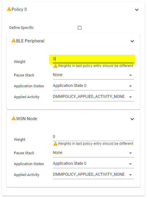
Now we will fix the warning from the DMM component. What has happened is that the initial generated DMM policy table contains a single DMM policy which has invalid weights. Long story short, the last policy entry in the policy table must have different weights, so that is what we are going to do.
Navigate to the last DMM policy entry in the DMM policy table, and set the
weight for the BLE Peripheral to 1. All warnings should now disappear, and
the yellow warning sign next to the DMM component should now become a green
checkmark.
Now we will create the different application states for each protocol stack. This is, as stated before, completely user defined and can be any number of application states. For this task, we will use the following application states:
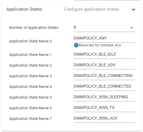
Modified SysConfig file
Make sure to save the SysConfig file.
Configure DMM in main.c
Next is to modify main.c, which is located under the Startup/ folder, to
use DMM:
Include the following header files at the top:
dmm/dmm_policy.hdmm/dmm_scheduler.hdmm/dmm_priority_ble_wsn.hsyscfg/ti_dmm_application_policy.h
Initialize and open the DMM Policy Manager using the global priority table defined inside
dmm_priority_ble_wsn.hand the policy table defined insideti_dmm_application_policy.h.- The relevant APIs are found in
dmm_policy.h.
- The relevant APIs are found in
Initialize and open the DMM Scheduler using the policy table defined inside
ti_dmm_application_policy.h.- The relevant APIs are found in
dmm_scheduler.h.
- The relevant APIs are found in
Register clients with the DMM scheduler with for both protocol stack roles. Note that the registered client is a pointer to the TI-RTOS Task handle of a corresponding stack role which calls the RF driver APIs.
- For the BLE peripheral, the BLE Stack Task handle can be extracted by
calling
ICall_getRemoteTaskHandle(0).
- For the BLE peripheral, the BLE Stack Task handle can be extracted by
calling
Set the initial DMM application state for each protocol stack role.
- The application state for BLE peripheral should be set to
DMMPOLICY_BLE_ADV.
- The application state for BLE peripheral should be set to
At the top of main.c include the relevant header files.
    /* Include DMM module */
    #include "dmm/dmm_policy.h"
    #include "dmm/dmm_scheduler.h"
    #include "dmm/dmm_priority_ble_wsn.h"
    #include "syscfg/ti_dmm_application_policy.h"
main.c – DMM includes
Inside main(), do the following changes.
    int main()
    {
        // =========== ADD START ===========
        Task_Handle* pBleTaskHndl;
        DMMPolicy_Params dmmPolicyparams;
        DMMSch_Params dmmSchParams;
        // =========== ADD END ===========

        ...

        /* Start tasks of external images - Priority 5 */
        ICall_createRemoteTasks();
        // =========== ADD START ===========
        pBleTaskHndl = ICall_getRemoteTaskHandle(0);
        // =========== ADD END ===========

        ...
        // =========== ADD START ===========
        /* Initialize and open the DMM policy manager */
        DMMPolicy_init();
        DMMPolicy_Params dmmPolicyParams;
        DMMPolicy_Params_init(&dmmPolicyParams);
        dmmPolicyParams.numPolicyTableEntries = DMMPolicy_ApplicationPolicySize;
        dmmPolicyParams.policyTable = DMMPolicy_ApplicationPolicyTable;
        dmmPolicyParams.globalPriorityTable = globalPriorityTable_bleLwsnH;
        DMMPolicy_open(&dmmPolicyParams);

        /* Initialize and open the DMM scheduler */
        DMMSch_init();
        DMMSch_Params_init(&dmmSchedulerParams);
        memcpy(dmmSchedulerParams.stackRoles,
               DMMPolicy_ApplicationPolicyTable.stackRole,
               sizeof(DMMPolicy_StackRole) * DMMPOLICY_NUM_STACKS);
        dmmSchedulerParams.indexTable = DMMPolicy_ApplicationPolicyTable.indexTable;
        DMMSch_open(&dmmSchedulerParams);

        /* Register clients with DMM scheduler */
        DMMSch_registerClient(pBleTaskHndl, DMMPolicy_StackRole_BlePeripheral);

        /* Set the initial application states */
        DMMPolicy_updateStackState(DMMPolicy_StackRole_BlePeripheral, DMMPOLICY_BLE_ADV);
        // =========== ADD END ===========

        /* enable interrupts and start SYS/BIOS */
        BIOS_start();

        return(0);
    }
main.c – initialize and open DMM
Modify the Project Zero Application
Next is to make the BLE-stack DMM aware and modify the Project Zero application to update the current application state. There is no correct way to define when to update application states; it is up to you, the developer, to decide what makes sense.
For this lab, the BLE-stack is either in the advertising or connected state. An fairly straightforward implementation would be to define the application state based on the internal BLE-stack state. For instace, we could define the application state to be connected when the internal state is in the Slave state, and advertising for any other internal state.
In order to do this, we need to configure a .fastStateUpdateCb and
.bleStackType for the BLE-stack, which allows the application to receive a
callback every time the internal stack state changes.
Do the following:
We need to modify the
ble_user_config.c, however, it is linked to the original file in the SDK. In order not to modify the original file, we will replace the linked file with a local copy.Remove the linked
ble_user_config.c, found under theiCallBLE/folder.Copy
ble_user_config.cfrom the SDK, found under<SDK>/source/ti/ble5stack/icall/app/, to theiCallBLE/folder.
Inside
ble_user_config.c, specify the.fastStateUpdateCbto beProjectZero_fastStateUpdateCband the.bleStackTypeasDMMPolicy_StackRole_BlePeripheral.You can find the location of the variables inside the
bleStackConfigstructure.Also make sure to include the
project_zero.hfile, as we will defineProjectZero_fastStateUpdateCbinsideproject_zero.c.// Include application headers #include "project_zero.h" #include "dmm/dmm_policy.h" // BLE Stack Configuration Structure const stackSpecific_t bleStackConfig = { /* ... omitted ... */ .fastStateUpdateCb = ProjectZero_fastStateUpdateCb, .bleStackType = DMMPolicy_StackRole_BlePeripheral /* ... omitted ... */ };ble_user_config.c – DMM ready BLE-stack config
Declare the
ProjectZero_fastStateUpdateCb()function inproject_zero.h.extern void ProjectZero_fastStateUpdateCb(uint32_t stackType, uint32_t stackState);project_zero.h –
ProjectZero_fastStateUpdateCb()declarationDefine the
ProjectZero_fastStateUpdateCb()function inproject_zero.c.#include "dmm/dmm_policy.h" #include "syscfg/ti_dmm_application_policy.h" void ProjectZero_fastStateUpdateCb(uint32_t StackRole, uint32_t stackState) { if (StackRole == DMMPolicy_StackRole_BlePeripheral) { static uint32_t prevStackState = 0; /* Transition to Slave state */ if (!(prevStackState & LL_TASK_ID_SLAVE) && (stackState & LL_TASK_ID_SLAVE)) { DMMPolicy_updateStackState(DMMPolicy_StackRole_BlePeripheral, DMMPOLICY_BLE_CONNECTED); } /* Transition from Slave state */ else if ((prevStackState & LL_TASK_ID_SLAVE) && !(stackState & LL_TASK_ID_SLAVE)) { DMMPolicy_updateStackState(DMMPolicy_StackRole_BlePeripheral, DMMPOLICY_BLE_ADV); } prevStackState = stackState; } }project_zero.c –
ProjectZero_fastStateUpdateCb()definitionOptimize application state updates
The BLE-Stack can call the registered
.fastStateUpdateCbmultiple times as it changes state internally. In order to minimize the calls toDMMPolicy_updateStackState(), we only update the application state whenstackStatetransitions from any state toLL_TASK_ID_SLAVE.Build the project and flash the device. You should experience the exact same behavior and printouts as before adding the DMM.
Good work!
You have now DMM enabled Project Zero! In order to observe any meaningful difference, we need to have a secondary stack running concurrently. Time to add the WSN Node.
Adding WSN Node alongside Project Zero
Again, for the sake of simplicity, we will re-use one of the existing WSN Node
DMM examples. A good candidate for this is the WSN Node from the
dmm_wsnnode_ble_sp example.
Why not use the WSN Node from dmm_wsnnode_remote_display?
It is more convenient! The WSN Node application inside
dmm_wsnnode_remote_display is tied together with the BLE Peripheral
application in order to print to the console.
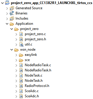
Copy over the wsn_node/ folder inside the Application/ folder. You can do
this by drag-and-dropping the whole source code folder found inside
<SDK>/source/ti/dmm/apps/dmm_wsnnode_ble_sp/source.
Your project explorer should now look something like this:
WSN Node Configuration
This example is currently only available as an CC1352R1 example but we can still reuse the WSN node for the other device variants; keep in mind that you will have to adjust the WSN Node settings to fit your WSN Collector device.
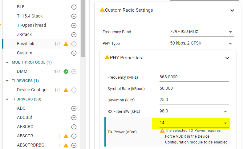
First we need to configure EasyLink in SysConfig, as the WSN Node application expects configuration files from SysConfig for EasyLink.
Open SysConfig by double clicking the
project_zero.syscfgfile.Add the EasyLink component by clicking the pluss sign next to the name.
You will initially get a warning from the EasyLink component. This is because the default TX power value is set to the highest value, which requires Force VDDR to be enabled. We can fix this by simply changing the default TX power in EasyLink to something lower.
Make sure the rest of the configuration matches the one to the WSN Concentrator device you used earlier in the lab.
Lastly, we need to make a TRNG handle for EasyLink, which expects the name
CONFIG_TRNG_EASYLINK. Use default configuration.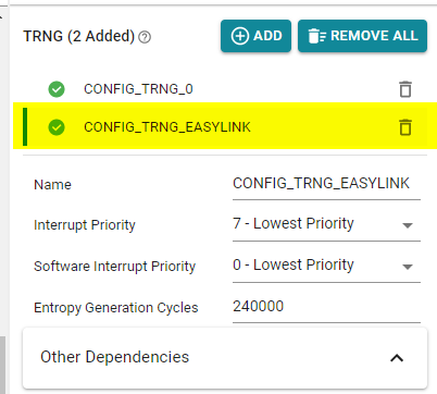
We need to add the pre-define USE_DMM_BLE_SP, because the WSN Node
application will use some none existing code for remote display if we don't.
In addition, setting the POWER_MEAS_DMM_WSN define makes sure the WSN Node
is not using LEDs.
Navigate to
Project Properties→Build→ARM Compiler→Predefined Symbols.Add the following pre-define:
USE_DMM_BLE_SPPOWER_MEAS_DMM_WSN
In order for the project to find the recently added files, add the following include search paths in the project properties:
Navigate to
Project Properties→Build→ARM Compiler→Include Options.Add the following search paths:
${PROJECT_ROOT}/Application/wsn_node
Now we need to initialize the WSN Node application and register it with the
DMM. Do the necessary changes inside main.c to setup the WSN Node and
register DMM:
Include
node_radio_task.h.Initialize the WSN Node.
Register the WSN Node client with the DMM scheduler.
Set the initial WSN Node stack state to be in sleeping mode.
The following changes need to be done to the main function:
#include "NodeTask.h"
#include "NodeRadioTask.h"

int main()
{
    Task_Handle *pBleTaskHndl;
    // =========== ADD START ===========
    Task_Handle *pWsnTaskHndl;
    // =========== ADD END ===========
    DMMPolicy_Params dmmPolicyParams;
    DMMSch_Params dmmSchedulerParams;

    /* Register Application callback to trap asserts raised in the Stack */
    RegisterAssertCback(AssertHandler);

    Board_initGeneral();

    ...

    ProjectZero_createTask();

    // =========== ADD START ===========
    /* Initialize wsn sensor node tasks */
    pWsnTaskHndl = NodeRadioTask_init();
    NodeTask_init();
    // =========== ADD END ===========

    /* initialize and open the DMM policy manager */
    DMMPolicy_init();
    DMMPolicy_Params_init(&dmmPolicyParams);
    dmmPolicyParams.numPolicyTableEntries = DMMPolicy_ApplicationPolicySize;
    dmmPolicyParams.policyTable = DMMPolicy_ApplicationPolicyTable;
    dmmPolicyParams.globalPriorityTable = globalPriorityTable_bleLwsnH;
    DMMPolicy_open(&dmmPolicyParams);

    /* initialize and open the DMM scheduler */
    DMMSch_init();
    DMMSch_Params_init(&dmmSchedulerParams);
    memcpy(dmmSchedulerParams.stackRoles, DMMPolicy_ApplicationPolicyTable.stackRole, sizeof(DMMPolicy_StackRole) * DMMPOLICY_NUM_STACKS);
    dmmSchedulerParams.indexTable = DMMPolicy_ApplicationPolicyTable.indexTable;
    DMMSch_open(&dmmSchedulerParams);

    /* register clients with DMM scheduler */
    DMMSch_registerClient(pBleTaskHndl, DMMPolicy_StackRole_BlePeripheral);

    // =========== ADD START ===========
    DMMSch_registerClient(pWsnTaskHndl, DMMPolicy_StackRole_WsnNode);
    // =========== ADD END ===========

    /*set the stacks in default states */
    DMMPolicy_updateStackState(DMMPolicy_StackRole_BlePeripheral,
                               DMMPOLICY_BLE_ADV);

    // =========== ADD START ===========
    DMMPolicy_updateStackState(DMMPolicy_StackRole_WsnNode,
                               DMMPOLICY_WSN_SLEEPING);
    // =========== ADD END ===========

    /* enable interrupts and start SYS/BIOS */
    BIOS_start();

    return(0);
}
main.c – WSN Node stack registered alongside the BLE-Stack
Build and download the project to the device, if you did everything correctly you should now also see a WSN Node connecting to your WSN Concentrator.
Congratulations!
You now have a Project Zero BLE Peripheral running on your device together with a WSN Node.
Feeling adventurous? Why not try too add a service to Project Zero that allows you to interact with the WSN Node and the Concentrator. If this sounds like fun, a good starting point is the BLE Custom Profile lab.
This work is licensed under a Creative Commons Attribution-NonCommercial-NoDerivatives 4.0 International License.