Introduction
This module is a study of the Angle of Arrival (AoA). AoA is a technique for finding the direction that an incoming packet is coming from. The estimated time to complete this lab is between 2-3 hours. It is assumed that the reader has a basic knowledge of embedded C tool chains and general C programming concepts.
This lab is based on the rtls_master, rtls_slave and rtls_passive projects that are part of
the SimpleLink™ CC13X2 / CC26X2 SDK.
First, the lab will cover an overview on how to get started with the AoA projects. Subsequent tasks of this lab will guide the user on how to customize these projects in order to answer most of the common AoA questions.
Prerequisites
Recommended reading
These chapters in the TI BLE5-Stack User's Guide
- TI BLE5-Stack Quick Start
- The CC13x2 or CC26x2 SDK Platform
- Application
- BLE5-Stack
- RTLS Toolbox
- Network Processor Interface (NPI)
Project readme files:
rtls_masterReadme located in <SimpleLink CC13X2 / CC26X2 SDK> → examples → rtos → Board → ble5stack → rtls_master folder within the CC13X2 / CC26X2 SDK.- All relevant information to
rtls_slaveandrtls_passiveis contained in thertls_masterreadme rtls_agentReadme located in <SimpleLink CC13X2 / CC26X2 SDK> → tools → ble5stack → rtls_agent folder within the CC13X2 / CC26X2 SDK. This will be covered in detail in Task 2.
Software for desktop development
- SimpleLink CC13X2-26X2 SDK 4.20
- Those listed under the Dependencies section of the CC13x2-26x2 SDK Release Notes
This module requires the following kits:
- 2x or 3x SimpleLink™ CC26x2R LaunchPad™
- 1x or 2x BOOSTXL-AoA
Getting started with AoA booster pack
Getting started – Desktop
At the end of this task you must have:
- SimpleLink CC13X2-26X2 SDK installed
- Working Python environment
- Used
rtls_example.pyscript that sets up an RTLS network. - A basic knowledge of the positioning techniques
- Used the RTLS toolbox and the RTLS UI
Install the Software
- Run the SimpleLink CC13X2 / CC26X2 SDK installer.
- Install Python 3.7 or later from the Python Download page.
- Setup the Python environment as described in the README.md in <SimpleLink CC13X2 / CC26X2 SDK> → tools → ble5stack → rtls_agent folder.
- If a bash environment doesn't exist on your system, install Git bash
This gives you:
- The SDK with TI-RTOS included at
<SIMPLELINK_CC13X2_26X2_SDK_INSTALL_DIR>which defaults toC:\ti\simplelink_cc13x2_26x2_sdk_x_xx_xx_xx. - Python 3.7 environment with all dependencies required by the RTLS Node Manager
Load the software
- Load Board #1 + BOOSTXL-AoA with
rtls_passiveproject:
<SimpleLink CC13X2 / CC26X2 SDK> → examples → rtos → CC26X2R1_LAUNCHXL → ble5stack → rtls_passive - Load Board #2 with
rtls_slaveproject:
<SimpleLink CC13X2 / CC26X2 SDK> → examples → rtos → CC26X2R1_LAUNCHXL → ble5stack → rtls_slave - Load Board #3 with
rtls_masterproject:
<SimpleLink CC13X2 / CC26X2 SDK> → examples → rtos → CC26X2R1_LAUNCHXL → ble5stack → rtls_master
Localization Techniques
A Real Time Localization System can be defined as a system capable of determining the position of a target within a defined physical area in real time. The physical area is normally defined through deployment of reference/locator nodes.
There are two fundamentally different approaches to location finding:
Trilateration, where you know the distance between a reference node and a target node. RSSI based techniques are typical examples of trilateration.
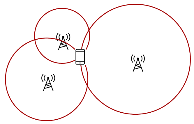
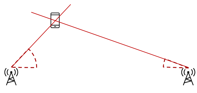
Triangulation, where you know the direction from a reference node to a target
node. Angle of Arrival is a technique that can be used to measure the angle
from the receiver to the transmitter.
What is a node?
A node in this case is referred to as a localization capable embedded device. For the demos in the SDK, nodes are LaunchPads
Quiz!
Select the localization techniques based on trilateration...
Select the localization techniques based on triangulation...
RTLS Toolbox Introduction
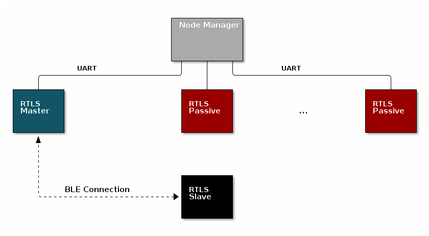
In the previous paragraph, we discussed how multiple AoA nodes can combine angle information to perform triangulation. It is important to remember in the pictures above, it is not possible for one single node to localize an object using the TI sample applications. A single AoA node only produces one angle. By nature this is an ambiguous measurement. If there are at least two nodes providing AoA data, then localization can occur. This requires a fourth device that is capable of combining the samples from the individual nodes and finding the intersection.
The intersection between the angles (AoA) is the estimated location of the device. An overview of the topology is shown below. In the diagram below, the black, blue, and red boxes represent CC26x2R LaunchPads while the grey box is a PC.
For a comprehensive presentation of the RTLS toolbox and its software components, please see the TI BLE5-Stack User's Guide
RTLS Roles and Topology
Each node in an RTLS network utilizes the software components listed above
in a different role to perform a specific task related to localization. There are
three examples: rtls_master, rtls_slave, and rtls_passive. The capabilities
of these examples are explained below.
RTLS Master
The RTLS master runs a full BLE-Stack and acts as a BLE central device. It will scan and connect to the RTLS slave over BLE. Once a connection is established the RTLS Master will do the following:
- Share the connection parameters (access address, master sleep clock accuracy, and CRC init) with the PC.
- Use the BLE link to share AoA parameters with the peripheral device.
- (Possibly) Receives packets with CTE and performs in-phase and quadrature component (IQ) sampling
- The RTLS master does not send out AoA packets, but configures the slave to do so.
RTLS Slave
The RTLS slave runs a full BLE-Stack and acts as a BLE peripheral device. This is the device that is to be located. The slave device will advertise and enter a connection with the RTLS Master.
- Advertises special string to be detected by
rtls_master(covered in detail in Task 3) - BLE-Stack peripheral role
- Sends data packets with AoA tone embedded using Constant Tone Extension (CTE). More information on CTE can be found in the Bluetooth 5.1 Core Spec
- Wireless/battery operated, not connected to PC
RTLS Passive
The RTLS passive does not actively participate in the BLE connection between the RTLS master and slave. Instead, it uses the Micro BLE-Stack in connection monitoring mode to follow the connection. To do this, the passive device relies on the Master to distribute the connection parameters once a connection is formed. The passive node does the following:
- Receives packets with CTE and performs in-phase and quadrature component (IQ) sampling
- Uses Micro BLE-Stack in Connection Monitoring mode to follow connection between master and slave
Note: The RTLS passive can be used but is not necessary.
PC/Central Processing Node
The PC node is responsible for controlling the embedded RTLS nodes by sending commands and processing events. In the SDK, this is realized by a combination of a Python layer that implements the UNPI master role and a server that translates UNPI commands to a socket interface that is used by the User Interface (UI) application running in the browser. In a final product, these algorithms may be implemented on an embedded device or even perhaps the RTLS master node.
The PC implements the following functionality in the RTLS GUI:
- Communicate via REST API's with RTLS_Util to issue commands and extract received RTLS Data from devices
- Graphing and logging data
- Enumerate devices
- Distribute connection parameters to passive nodes
Quiz!
Is it possible to have multiple RTLS passive devices in a network?
Why would multiple passive devices be desirable? (select all that apply)
Running the RTLS Visual Demo
In this sub-part, we are going to use the UI (User Interface). This tool runs on a computer. You will find RTLS_UI in <SimpleLink CC13X2 / CC26X2 SDK> → tools → ble5stack → rtls_agent → rtls_ui folder.
Apply any fixes from the RTLS known issues page on E2E
Build the projects and flash the LaunchPads as described before
Connect the master and passive devices to the computer. The slave device must be powered but does not require to be connected to the computer.
Execute the program
rtls_ui(stored <SimpleLink CC13X2 / CC26X2 SDK> → tools → ble5stack → rtls_agent → rtls_ui)This will open your default web-browser and connect you to a local server. If your default browser is not supported (typically if your default web browser is IE), you will have to copy-paste the address of the server in a supported web browser.
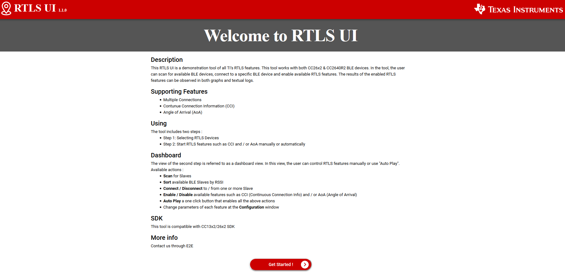
Review RTLS UI's welcome page, then click on "Get Started!"
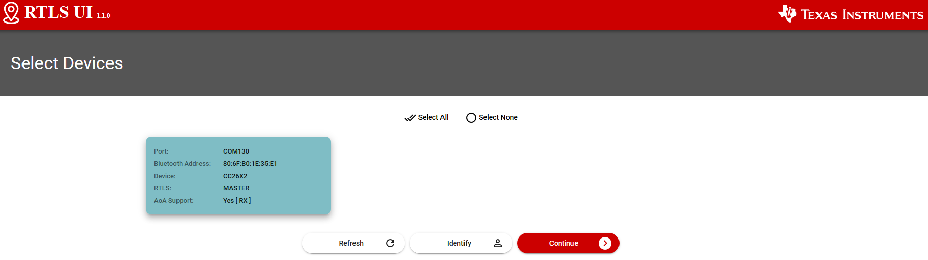
The UI will display the devices detected. The UI only detects the RTLS receivers (i.e. the master and passive devices). The UI will NOT display the slave device(s) eventually connected to the computer.
Select the launchpad(s) to use. Only the master and (eventually) passive devices have to be selected. Once done, click on "Continue"
The system is ready! Click on "Auto Play" to start the demo:
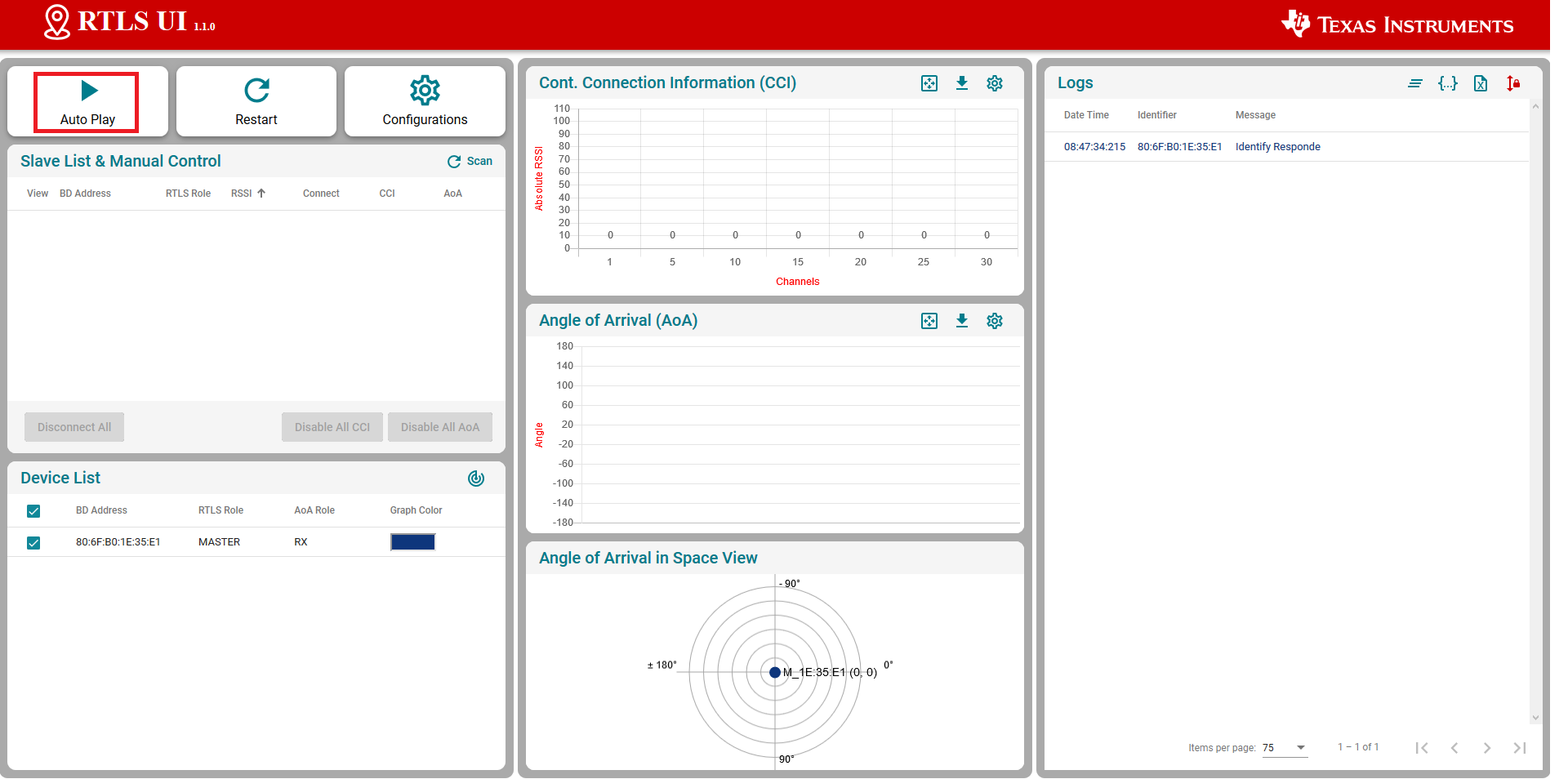
This will automatically:
- launch a scan to detect the slave device
- connect the slave device
- enable continuous connection information monitoring
- enable AOA measurement
Running the RTLS Non-Visual Demo
In this sub-part we are going to use a Python script to directly interact with the nodes.
This gives power to the developer to define
custom behavior of the RTLS network and control the devices directly.
Specifically, this will cover setting up the required Python dependencies and
running the rtls_example_with_rtls_util.py template script provided in the SDK.
Assumptions and Notation
Before starting this task the following is assumed
- A command prompt supporting bash or Git bash is open and running.
- Unix style slashes will be used throughout. If it is necessary to run these
steps in the Windows Command Prompt (
cmd.exe), then/should be replaced with\. - Various command prompts will search your [System Path variable][1] to find Python. If you have a pre-existing Python version in your path this may be selected over the newly installed version. To prevent mixing the two up, we will use virtual environments.
- We assume that Mac users don't have another instance of Python 3 installed.
If this is not the case, then based on the
PATHvariable an older version of Python may be selected with invoking thepython3command. Be sure to invoke the correct version of Python. - Here we re-hash some of the instructions from the rtls_agent/readme.html. Some steps may be redundant if you already followed this and have the python environment setup.
- Please have a look to the README file stored in tools\ble5stack\rtls_agent\rtls_util
- Install Python per steps in Getting started
- Open a command prompt (Git Bash is recommended)
Create a Python virtual environment
- Navigate to the SDK folder (e.g.
C:\ti\simplelink_cc13x2_26x2_sdk_x_xx_xx_xx\tools\ble5stack\rtls_agent) - Execute
py -3.7 -m venv .venv(windows) orpython3 -m venv .venv(mac). - This will create a folder called
.venvin the current directory that includes a copy of the python interpreter and a sandbox for installing packages. - Activate virtual environment using
source .venv/Scripts/activate(bash) or.venv\Scripts\activate.bat(Windows cmd) - Observe that when a venv is activated
(.venv)will appear before each cmd prompt - Notice that once the virtual environment is activated, the
pythoncommand will use the local Python interpreter in the venv. See Virtual Environments for more info.
- Navigate to the SDK folder (e.g.
Install RTLS packages
This step will use package.bat (for Windows) or package.sh (for Linux / Mac) to install the RTLS packages.
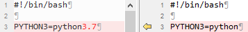
Workaround to deal with hard-coding in package install scripts
Unfortunately the package install script hard-codes the python 3 location. This does not work if you have created a virtual environment as per the previous step. To fix this:
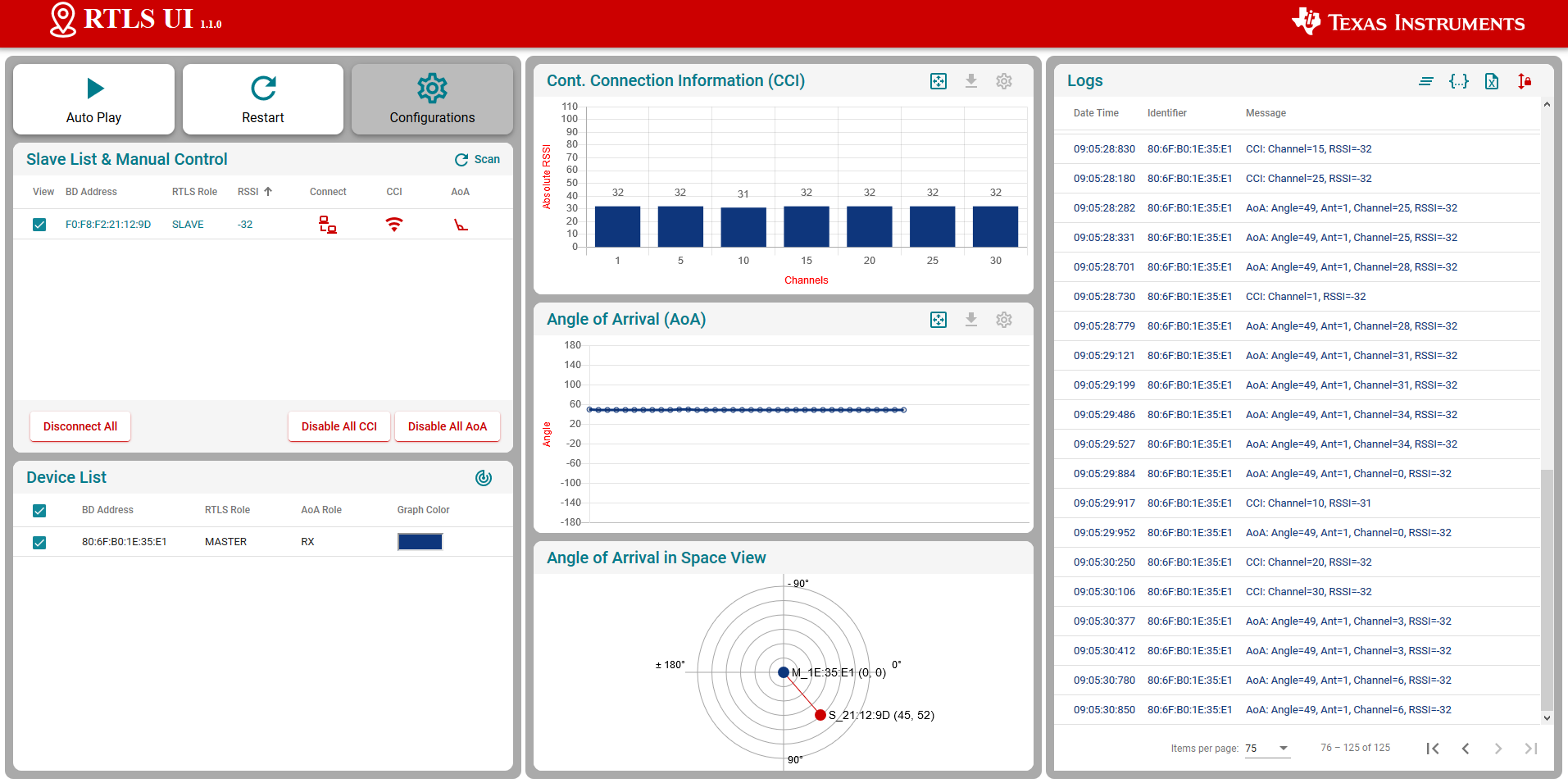
- In Windows, make the following change (code on right is fixed version):
- In Linux/Mac, make the following change (code on right is fixed version):
- In Windows, run
winpty ./package.bat -c -b -u -i(winpty must be omitted if you are using PowerShell or CMD terminal). In Linux / Mac runpackage.sh -c -b -u -i
- In Windows, make the following change (code on right is fixed version):
Install required external Python Dependencies into the newly created virtual environment
- Execute
python -m pip --proxy www.proxy.com install -r requirements.txt - Note that above
--proxy www.proxy.comis only required if behind a proxy. www.proxy.comis an example of a proxy. It should be replaced with the web address of your specific proxy if applicable.- This will install the required external Python packages that are needed by the RTLS
Python suite (these are listed in
requirements.txt).
- Execute
Open the
examples/rtls_example_with_rtls_util.py, find and update the following lines.devices = [ {"com_port": "COM37", "baud_rate": 460800, "name": "CC26x2 Master"}, {"com_port": "COM29", "baud_rate": 460800, "name": "CC26x2 Passive"},Make sure to list all the master and passive LaunchPads used an to update properly the COM ports used. It is not required to add the slave device to this list.
Note
The "name" field above does not affect the functionality. It is simply used for logging purposes and therefore it is not required to modify this if not desired.
Save the file and run it using
python -u examples/rtls_example_with_rtls_util.py.- The script will scan for RTLS devices, connect, and then print continuous connection information (RSSI, channel) for 5 seconds.
- See below for sample output snippet (note that the addresses and COM ports will be different).
- The out-of-box demo only reports continuous connection information (CCI). The following sections will help you to leverage all the capabilities of the provided scripts.
Master : <RTLSNode(CC26x2 Master, started 22068)>
Passives : [<RTLSNode(CC26x2 Passive, started 23740)>]
All : [<RTLSNode(CC26x2 Passive, started 23740)>, <RTLSNode(CC26x2 Master, started 22068)>]
Devices Reset
Start scan for 15 sec
Scan Results: [{'addr': '80:6F:B0:1E:3A:8B', 'addrType': 0, 'rssi': -61}]
Connection Success
CCI Callback Set
[08:10:2020 13:59:38:441627] : {"name": "CC26x2 Passive", "type": "conn_info", "identifier": "80:6F:B0:1E:37:14", "payload": {"rssi": -71, "channel": 13}}
[08:10:2020 13:59:38:443650] : {"name": "CC26x2 Master", "type": "conn_info", "identifier": "80:6F:B0:1E:3F:06", "payload": {"rssi": -51, "channel": 2}}
CCI Started
Going to sleep for 5 sec
[08:10:2020 13:59:38:544616] : {"name": "CC26x2 Passive", "type": "conn_info", "identifier": "80:6F:B0:1E:37:14", "payload": {"rssi": -72, "channel": 24}}
[08:10:2020 13:59:38:544616] : {"name": "CC26x2 Master", "type": "conn_info", "identifier": "80:6F:B0:1E:3F:06", "payload": {"rssi": -51, "channel": 13}}
[08:10:2020 13:59:38:644620] : {"name": "CC26x2 Passive", "type": "conn_info", "identifier": "80:6F:B0:1E:37:14", "payload": {"rssi": -75, "channel": 35}}
[08:10:2020 13:59:38:644620] : {"name": "CC26x2 Master", "type": "conn_info", "identifier": "80:6F:B0:1E:3F:06", "payload": {"rssi": -50, "channel": 24}}
[08:10:2020 13:59:38:746616] : {"name": "CC26x2 Passive", "type": "conn_info", "identifier": "80:6F:B0:1E:37:14", "payload": {"rssi": -74, "channel": 9}}
[08:10:2020 13:59:38:746616] : {"name": "CC26x2 Master", "type": "conn_info", "identifier": "80:6F:B0:1E:3F:06", "payload": {"rssi": -49, "channel": 35}}
[08:10:2020 13:59:38:845621] : {"name": "CC26x2 Passive", "type": "conn_info", "identifier": "80:6F:B0:1E:37:14", "payload": {"rssi": -70, "channel": 20}}

...

[08:10:2020 13:59:43:257107] : {"name": "CC26x2 Passive", "type": "conn_info", "identifier": "80:6F:B0:1E:37:14", "payload": {"rssi": -71, "channel": 23}}
[08:10:2020 13:59:43:259117] : {"name": "CC26x2 Master", "type": "conn_info", "identifier": "80:6F:B0:1E:3F:06", "payload": {"rssi": -49, "channel": 12}}
[08:10:2020 13:59:43:355919] : {"name": "CC26x2 Passive", "type": "conn_info", "identifier": "80:6F:B0:1E:37:14", "payload": {"rssi": -76, "channel": 34}}
[08:10:2020 13:59:43:359918] : {"name": "CC26x2 Master", "type": "conn_info", "identifier": "80:6F:B0:1E:3F:06", "payload": {"rssi": -49, "channel": 23}}
[08:10:2020 13:59:43:458910] : {"name": "CC26x2 Passive", "type": "conn_info", "identifier": "80:6F:B0:1E:37:14", "payload": {"rssi": -74, "channel": 8}}
[08:10:2020 13:59:43:461956] : {"name": "CC26x2 Master", "type": "conn_info", "identifier": "80:6F:B0:1E:3F:06", "payload": {"rssi": -49, "channel": 34}}
Try to stop CCI result parsing thread
STOP Command Received
CCI Stopped
Master Disconnected
Done
Why is it recommended to create a virtual Python environment (select all that apply)?
Building Custom RTLS Python Scripts
With the environment setup, it is time for us to use Python directly to control the RTLS nodes. The goal of this task is to explain the RTLS PC software and to walk through setting up a RTLS network.
You might want to revision or make a copy of the default rtls_example_with_rtls_util.py so it is
preserved. Save it with another name like rtls_example_old.py as a backup.
RTLS Node Manager Python Overview
First, we will briefly discuss the important layers of the Python solution and their role.
/rtls_agent
    /examples/
      rtls_example_with_rtls_util.py - Example to exercise rtls_util functionality
      rtls_aoa_iq_with_rtls_util_export_into_csv.py - Example to store the IQ data (or AOA) to a file on your computer
      rtls_aoa_multi_conn_example.py - Example to exercice the multi-connections capability of the RTLS devices
    /rtls_util/
         Main interface for examples. Class that abstracts RTLSManager and RTLSNode
         functionality. Handles waiting for RTLS responses in order to provide synchronous
         API's.  Raises any unexpected functionality as an exception.
         Please review the README file for details.

    /rtls/
        /rtls/
            rtlsmanager.py - Class to manage multiple nodes in an RTLS network.
                             Subscribes to incoming data from the nodes, routes
                             outgoing data to each of the nodes. Distributes
                             connection parameters from master node to any
                             connected passive nodes when an connection is
                             established. Handles messages from rtls_agent_cli server
                             if one is provided.

            rtlsnode.py -    Class that implements the basic functionality of a node
                             in an RTLS network. This class will query the embedded
                             device connected to it and determine its capabilities.
                             Essentially this assigns a role in an RTLS context to
                             a COM port.

            ss_rtls.py       Defines the commands in the RTLS UNPI subsystem.
                             This file will define builder classes for the various
                             UNPI commands that the RTLS subsystem supports.

      /unpi/
          serialnode.py - Thread that manages serial communication from COM ports.
                          to higher layers.
                          Queues up messages and sends them to parser.
          unpiparser.py - Parser for Unified Network Processor Interface messages.
                          Implements UNPI frame format packing/unpacking.
RtlsUtil Summary
It is recommended to build RTLS based Python applications on top of the
RtlsUtil class within rtls_util.py. This class forms the RTLS API set. A call
to an RtlsUtil method translates to a sequence of one or more RTLS UNPI commands
/ responses from ss_rtls.py. In this way, RtlsUtil is an abstraction of both the
RTLS UNPI communication as well as the RTLSManager which manages the various
RTLSNode's.
Any errors in an RtlsUtil method will be reported as an exception raised to the
RtlsUtil consumer (i.e. rtls_example_with_rtls_util.py). Alternatively, if the
method returns, the functionality has been performed successfully.
Asynchronous localization data is received and stored into one of the following queues depending on the data:
- RtlsUtil.aoa_results_queue
- RtlsUtil.tof_results_queue
- RtlsUtil.conn_info_queue
RTLS Python Program Template
The rtls_example_with_rtls_util.py from the previous task
shows how to perform basic initialization of RtlsUtil as well
as setting up the networking and collecting localization data.
Here we highlight some of the important parts of the example:
The beginning of main() has several boolean variables to enable / disable
example functionality. It is possible to combine any of these modes together.
cci: Continuous Connection Informationaoa: Angle of Arrivalupdate_conn_interval: Updating Connection Interval
Out-of-box Functionality
The out-of-box functionality, as demonstrated above, only has continuous connection information enabled. AOA can be enabled too by setting the aoa variable to True
Common Initialization
There is initialization functionality that is common to all modes. First, construct an instance of the RTLSUtil class to serve as the RTLS Node Manager interface. The first parameter is the file to log debug information to and the second parameter is the logging level.
rtlsUtil = RtlsUtil(logging_file, RtlsUtilLoggingLevel.UTIL_ALL)
Then set the timeout property to specify how long (in seconds) to wait for a response
to a synchronous rtls command. A RtlsUtilTimeoutException will be raised
if no response is received in this time.
rtlsUtil.timeout = 30
Next, create a dictionary of devices and pass this to RTLS.set_devices() which
will create RTLSNode's for each device and an RTLSManager class using these
nodes.
devices = [
  {"com_port": "COM32", "baud_rate": 460800, "name": "CC26x2 Master"},
  {"com_port": "COM26", "baud_rate": 460800, "name": "CC26x2 Passive"},
]
Note
The "name" field above does not affect the functionality. It is simply used for logging purposes and therefore it is not required to modify this if not desired.
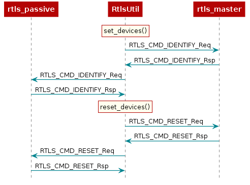
RTLS.set_devices() will send RTLS_CMD_IDENTIFY to each node to identify it's capabilities
and set the relevant master / passive(s).
Next, reset both nodes:
rtlsUtil.reset_devices()
The procedures above will appear, from a UNPI perspective, as the following:
RTLS Network Setup Procedure
At this point you should have a basic understanding of RTLS classes. Next we will cover the minimum commands required to setup an RTLS network.
In all cases a BLE connection is a prerequisite for performing localization.
The sequence diagram below shows the UNPI commands required to establish a connection between rtls_master and rtls_slave.
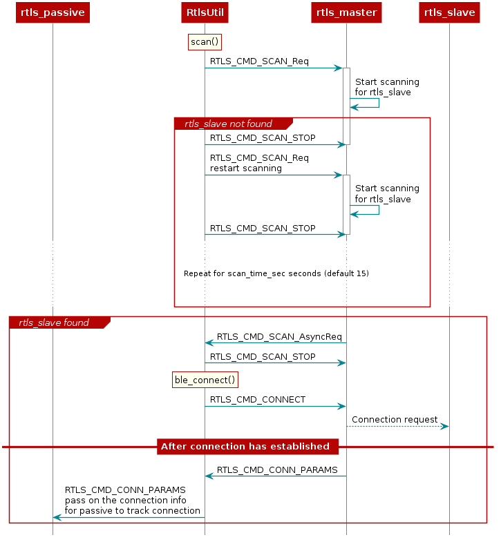
As covered in the BLE connections lab, before connecting, a scan must be
performed to see if the desired device is nearby. This is initiated by RtlsUtil.scan().
The scanning device will inspect the advertisement and optionally the scan response
data to determine if it wishes to connect to a given advertiser. Usually the
scanner is looking for a given token or string in the broadcast data of the advertiser.
The RTLS master will look for the string {'R','T','L','S','S','l','a','v','e'} starting
at the 3rd byte of the slave's advertisement data. If the advertising device
matches the filter, then it will be reported to the PC/Node Manager as
RTLS_CMD_SCAN responses which are returned from RtlsUtil.scan() as a list of
devices. If the advertising device does not match the filter, it will be discarded.
RtlsUtil.ble_connect() can be used to form a connection to one of the devices in the
scan results. This will inform rtls_master to form a connection by issuing an
RTLS_CMD_CONNECT along with the peer device's address and address type.
The address information can be extracted from the RTLS_CMD_SCAN responses
coming from the master node.
If the connection is successful, the RTLS_CMD_CONNECT response will be
received with status of RTLS_SUCCESS and RtlsUtil.ble_connect() will return.
The RTLS examples do not consider a connection to be established between master
and slave until the devices have paired and formed an L2CAP Connection Oriented
Channel (CoC). The L2CAP CoC is used to send RTLS sync related information
between master and slave. This can include AoA parameters or ToF parameters,
or a command to enable AoA or ToF.
Immediately after the BLE connection is established
(i.e. GAP_LINK_ESTABLISHED_EVENT received from the stack), the rtls_master
will share the connection parameters with the PC/Node Manager via
RTLS_CMD_CONN_PARAMS. This information is needed by the connection monitor
inside rtls_passive in order to follow the connection between RTLS master
and slave.
Distributing Connection Parameters
The RTLSManager Python class will immediately relay any connection
parameters received (RTLS_CMD_CONN_PARAMS) to all of the passive nodes
connected. This does not need to be done manually.
RTLS Passive Connection Lost
As its name suggests, the passive device does not have an active role in the BLE connection. The passive has only the capability to listen the link but is not able to require a retransmission if a packet is not properly received. As a result, and especially in noisy environments, the passive can lose track of the connection. In that case, the passive device needs to re-receive the (up to date) connection info to be able to listen the BLE link. This mechanism is not implemented in the out-of-the-box examples and you will be required to restart the demo if it happens.
Setting up RTLS Network in Python
Now that we understand the basics behind the RTLS network and how to set it up,
let's review how the rtls_example_with_rtls_util.py sample app sets up the RTLS network.
Note that the rtls_example_with_rtls_util.py will do some additional processing after the
network is setup. This is will be covered latter in this lab.
The commands required to setup a network belong to the RTLS UNPI subsystem and
can be found in the ss_rtls.py file. The sending and receiving of these commands
is abstracted through the RtlsUtil class.
Scanning for Devices
We will use the rtls_example_with_rtls_util.py as a starting point. From the sections
above, we know that after the nodes are identified, we want to tell the master
to scan. This is initiated as such:
scan_results = rtlsUtil.scan(scan_time_sec)
Alternatively, it is possible to only scan for a specific device address by passing a second "address" parameter as such:
scan_results = rtlsUtil.scan(scan_time_sec, slave_bd_addr)
After the scan completes (runs for scan_time_sec), the results are returned in
scan_results as a list of the following dictionaries:
{
    "addr" : 6 byte address as string,
    "addrType" : address type as int,
}
Asynchronous vs Synchronous commands in UNPI
The following provides more information about the RTLS UNPI commands. As mentioned
above, all of this is abstracted through RtlsUtil so can be skipped if desired.
You might have noticed that RTLS_CMD_SCAN is used to tell the node to start
scanning, receive status, and receive scan results.
This is possible within UNPI because each message can be one of the following
types
- Synchronous request
- Synchronous response
- Asynchronous request
In the case of RTLS_CMD_SCAN the message that initiates the scan on the
rtls_master is a synchronous request. The message that returns the status
of the scan start call is a synchronous response, and the message that
returns scan results is an asynchronous request. See the NPI chapter
in the [TI BLE5-Stack User's Guide]
for more information.
Connecting to a Device
Now, we have collected a list of scan results and are ready to connect. It is required to specify an address to connect to. The address can be hard-coded:
  slave_bd_addr = "80:6F:B0:1E:38:C3"
  rtlsUtil.ble_connect(slave_bd_addr, connect_interval_mSec)
If you don't know the address, you can read it from the UART
display of the slave device. Open a Serial terminal (like putty or Tera Term)
on the user/UART port of the rtls_slave LaunchPad. Use 115200 baud, 8N1.
It should show the following text:
Initialized
Dev Addr: 0x806FB01E3A8B
Advertising
Alternatively, the address can be extracted from the scan results as such:
rtlsUtil.ble_connect(scan_results[0], connect_interval_mSec)
Connection Interval
It is also necessary to pass a connection interval into RtlsUtil.ble_connect().
The ramifications of this parameter will be discussed in the various RTLS mode
documentation sections where relevant. The out-of-box example uses 100
milliseconds by default.
Remember, the rtls_master will automatically send the connection parameters
once a BLE connection is formed with the rtls_slave. The RTLSManager python
class will intercept this and distribute it to all rtls_passive nodes so we
don't have to do this in our program. Upon receiving the connection parameters,
the rtls_passive connection monitor will begin following the connection between
master and slave. Note that it may take some time to establish a connection as this
does include LE Secure Connections pairing as well as opening an L2CAP
Connection Oriented Channel.
Enabling Localization
Now that the connection has been formed and the connection parameter information has been distributed, it is time to enable one or more localization modes.
Continuous Connection Information
CCI is the default functionality of the out-of-box rtls_example_with_rtls_util.py. It is the
most simplistic method and only provides a received signal strength indicator (RSSI) and
frequency channel index for each BLE connection event.
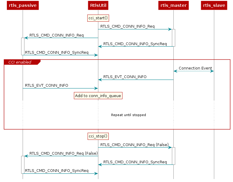
CCI can be enabled on both the master and the passive(s) by sending a RTLS_CMD_CONN_INFO UNPI
request. This is abstracted and initiated from RtlsUtil as such:
rtlsUtil.cci_start()
After being enabled, the respective node will send a RTLS_EVT_CONN_INFO UNPI Asynchronous Response
after each master-slave connection event. This response contains the RSSI and the channel of the
connection event. The master will send this after participating in the connection
event with the slave and the passive will send this after it observes the connection event.
RtlsUtil will receive each response and append it to the RtlsUtil.conn_info_queue. This queue
can then be processed as desired. The out-of-box example periodically reads and prints
from this queue in results_parsing() in a separate thread.
This procedure is shown here:
Miscellaneous Functionality
Stopping the Example
After enabling the localization mode(s), rtls_example_with_rtls_util.py will sleep for 5 seconds then
gracefully stop all ongoing over-the-air procedures and any spawned result-processing threads. If it is
desired to run for longer than 5 seconds, simply update the timeout_sec in the following code:
  timeout_sec = 5
  print("Going to sleep for {} sec".format(timeout_sec))
  timeout = time.time() + timeout_sec
  while timeout >= time.time():
      time.sleep(0.1)
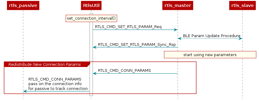
Updating Connection Interval
It is possible to dynamically update the connection interval of the master-slave BLE connection after
the connection has been established via RtlsUtil.set_connection_interval():
new_connect_interval_mSec = 80
rtlsUtil.set_connection_interval(new_connect_interval_mSec)
The new connection parameters are automatically distributed from the node manager to the passive devices so that they capable of maintaining synchronization with the connection after the update occurs. The procedure is shown here:
Introduction to AoA
Bluetooth Core Specification Version 5.1 introduces AoA/AoD which are
covered under Direction Finding Using Bluetooth Low Energy Device section.
AoA is for receivers that have RF switches, multiple antennas, can switch antennas and capture I/Q samples when receiving direction finding packets.
AoD is for transmitters that have RF switches, multiple antennas and can switch antennas when transmitting direction finding packets. And receivers only have one antenna but can capture I/Q samples when receiving direction finding packets.
| Direction Finding Method | Transmitter | Receiver |
|---|---|---|
| AoA | Single antenna, transmit CTE | Multiple antennas, RF switches, can switches antennas while capture I/Q data of the CTE |
| AoD | Multiple antennas, RF switches, transmit CTE while switching antennas | Single antenna, can capture I/Q data of the CTE |
On top of that, the Bluetooth Core Specification version 5.1 specifies the following states can support sending direction finding packets:
- Periodic advertising; also called
Connectionless CTE - Connection; also called
Connection CTE
The theory behind AoA/AoD and Connectionless/Connection CTE is the same, therefore in this SimpleLink Academy training, we will only focus on Connection CTE AoA.
We will explain the AoA theory first and the walk through our SimpleLink CC13X2 / CC26X2 SDK offering.
AoA measurement is typically a 3-step process:
- Collect phase information by sampling the I/Q
- Calculate the phase difference among the antennas
- Covert the phase difference into Angle of Arrival
1. Collect phase information by sampling the I/Q
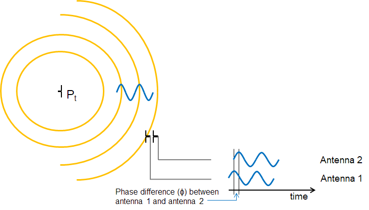
When two (or more) antennas are placed at a given distance apart from each other, their received RF signals will have a phase difference that is proportional to the difference between their respective distances from the transmitter.
Typically, the signal from one antenna will be a delayed version of the signal from the other antenna. If they are sufficiently close (less than Λ(wavelength)/2 between phase centers), you can always determine which is closest to the transmitter.
These path length differences will depend on the direction of the incoming RF waves relative to the antennas in the array. In order to measure the phase difference accurately, the radio wave packet must contain a section of constant tone with whitening disabled where there are no phase shifts caused by modulation.
Constant Tone Extension (CTE)
The constant tone extension is a section of consecutive 1's without whitening, which is effectively a +250kHz wave on top of the carrier wave. In the Bluetooth Core Specification Version 5.1, both periodic advertising packets and connection packets can contain a constant tone extension(CTE) after the CRC. The CTE can only be sent using uncoded PHY.
2. Calculate the phase difference among the antennas
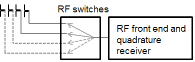
Phase Difference (Φ) is measured by connecting at least two antennas to the same receiver sequentially (more antennas can be added).
In order to get a good estimate of Φ (phase), all other intentional phase shifts in the signal should be removed. Connection CTE AoA solution achieves this by adding CTE at the end of packets.
 |
|---|
| Connection CTE Packet Format |
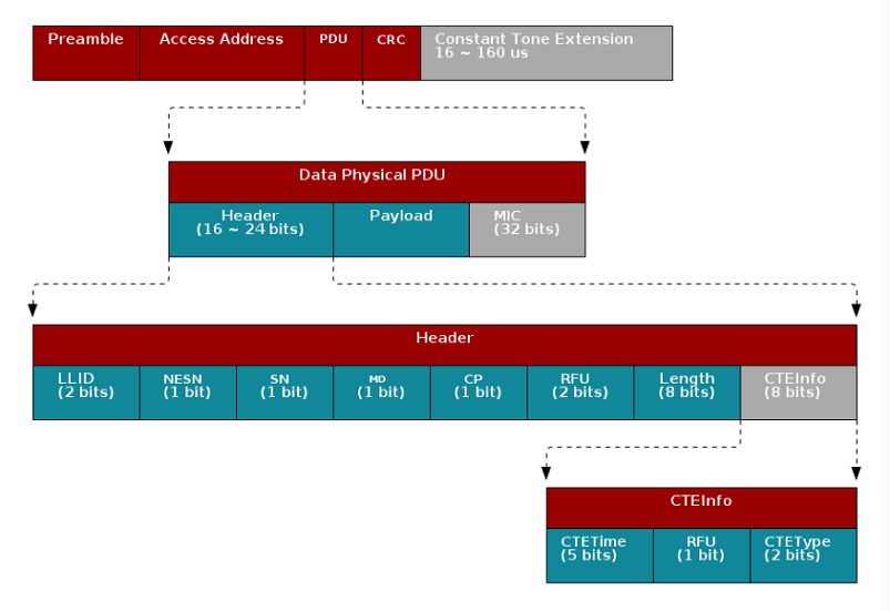
Data Physical Packet format
The grey colored part of the packet shown above means
it's optional. The Constant Tone Extension is only enabled when the CP bit
in the Data Physical PDU header is set. The detail of the Constant Tone
Extension is then specified by the CTEInfo field in the in the Data
Physical PDU.
This gives the receiver time to synchronize the demodulator first, and then store the I/Q samples from the CTE into radio RAM. The I/Q data is then extracted by the application layer.
I/Q samples are used to estimate phase difference among antennas. When the receiver gets AoA packets, the RF core will trigger an event that will lead to start of the antenna switching. The RF core will start sampling the I/Q data after the guard period of the CTE and the sampled data will be stored in the radio RAM.
By comparing the I/Q data collected from different antennas, users can get the relative phase difference among antennas.
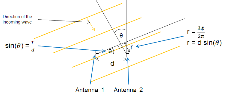
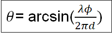
3. Convert the phase difference into Angle of Arrival
Last step is converting the phase shift (Φ) back to AoA (Θ).
If Φ is negative, this means that antenna 2 is ahead of antenna 1.
In this case Θ is negative too but this does not cause any
mathematical problem as sin() and arcsin() functions are defined
both for positive and negative numbers. To avoid any unnecessary complications
we will consider here Φ to be positive.
The angle between the incident wave and antenna array is Θ. Base on the picture below we know that the sin(Θ) = r/d, and d is the distance between antenna 1 and antenna 2 which is known. Then all we need to find out is r.
r is the distance to antenna 2 that the incident wave needs to travel after arriving at antenna 1. We have found that the phase difference between antenna 1 and antenna 2 is Φ, so the extra distance r is equal to wavelength of the incoming signal * Φ/(2Π).
r= Λ* Φ/(2Π)
Note
In rtls_passive example, you might notice that step 3 is not implemented.
The reason is simply because by step 2 using our
BOOSTXL-AoA we already have
linear result from +/-90 degree using antenna pair[1,2] and pair[2,3].
Therefore all we need is to have a look up table to do the fine tuning.
This saves computation time/current consumption compared to doing another arcsin function.
We also tried to do arcsin, but the result is pretty much the same as adding gain and offset after step 2.
What technique does AoA use to identify the direction of incident wave?
Task 1 – Running the AoA application
Have you moved the capacitor C51 of your LaunchPad to use external antenna?
If you have no idea what I am talking about, it's time for you to read the "Preparations" chapter of the Angle of Arrival BoosterPack Getting Started guide :)
The SimpleLink CC13X2-26X2 SDK
has three examples dedicated to performing AoA (rtls_master,
rtls_slave and rtls_passive).
In the TI BLE5-Stack User's Guide → RTLS Toolbox → Angle of Arrival → AoA application Overview, we have covered how the application works.
Therefore, after following the instruction on running the RTLS visual demo, you should be able to get it up and running.
An important remark before starting
Until the SDK version 3.30, the out-of-the-box example requires three LaunchPad devices (the master, the slave and the passive). The master was “only” responsible to maintain the BLE connection with the slave and to share the connection’s information with the passive device. The passive device was the only responsible to perform the AoA measurements.
Since SDK version 3.30, the master device can perform AoA measurements too. Of course this is only possible if it is equipped with a BOOSTXL-AoA. The master is still responsible to maintain the connection with the slave and to share the connection’s information with the passive device. As a result, you can choose to run the example with:
- both the master and the passive are performing AoA measurements
- only the passive is performing the measurements
- only the master is performing the measurements
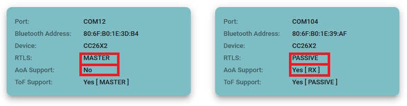
In this task, you will configure the example to suit best your needs. In the rest of the lab we will provide the steps assuming you are using both the master and the passive to perform the measurement. If this is not the case, you can basically ignore the steps that do not concern you.
Hardware settings:
Two BOOSTXL-AoA are required. One BOOSTXL-AoA must be on the passive device, the other must be on the master device.
Embedded Software settings:
In theory, no modification is required by the out-of-the-box software to run the demo. The guidance are provided for training purposes only.
rtls_passive: The passive's RTLS Control module needs the capability to act as RTLS Passive and AoA receiver. This capabilities are set modifying (if needed) the fieldrtlsCapabof thertlsConfigstructure (this must be done into themain.cfile which is stored under theStartupfolder). The capabilities we need for the lab are onlyRTLS_CAP_RTLS_PASSIVEandRTLS_CAP_AOA_RX.rtlsConfig.rtlsCapab = (rtlsCapabilities_e)(RTLS_CAP_RTLS_PASSIVE | RTLS_CAP_AOA_RX);main.c::main()
Note: The IOs and the switching pattern used by the antennas are provided through the overrides.
rtls_master: Ensure the master's RTLS Control module has the capability to act as a master (RTLS_CAP_RTLS_MASTER) and to receive the CTE (RTLS_CAP_AOA_RX).rtlsConfig.rtlsCapab = (rtlsCapabilities_e)(RTLS_CAP_RTLS_MASTER | RTLS_CAP_AOA_RX);main.c::main()
Note: The python script configures the master device in order to select the appropriate antennas and switching pattern. The default parameters are as following:
"aoa_cc26x2": {
  "aoa_slot_durations": 1,
  "aoa_sample_rate": 1,
  "aoa_sample_size": 1,
  "aoa_sampling_control": int('0x10', 16),
  ## bit 0   - 0x00 - default filtering, 0x01 - RAW_RF no filtering,
  ## bit 4,5 - default: 0x10 - ONLY_ANT_1, optional: 0x20 - ONLY_ANT_2
  "aoa_sampling_enable": 1,
  "aoa_pattern_len": 3,
  "aoa_ant_pattern": [0, 1, 2]
}
aoa_params used by default by the python script
rtls_slave: Ensure the slave's RTLS Control module has the capability to act as a slave (RTLS_CAP_RTLS_SLAVE) and to send out the CTE (RTLS_CAP_AOA_TX).rtlsConfig.rtlsCapab = (rtlsCapabilities_e)(RTLS_CAP_RTLS_SLAVE | RTLS_CAP_AOA_TX);main.c::main()
Once you have done the required modification on the embedded code, flash the LaunchPads and power-cycle them
RTLS UI settings:
Run the RTLS UI as explained before.
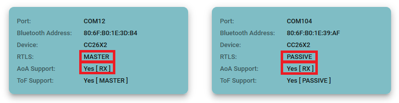
Verify if the passive's and master's capabilities listed by the RTLS UI match the settings you have previously done.
Hardware settings:
The BOOSTXL-AoA must be on the passive device.
Embedded Software settings:
rtls_passive: The passive's RTLS Control module needs the capability to act as RTLS Passive and AoA receiver. This capabilities are set modifying (if needed) the fieldrtlsCapabof thertlsConfigstructure (this must be done into themain.cfile which is stored under theStartupfolder). The capabilities we need for the lab are onlyRTLS_CAP_RTLS_PASSIVEandRTLS_CAP_AOA_RX.rtlsConfig.rtlsCapab = (rtlsCapabilities_e)(RTLS_CAP_RTLS_PASSIVE | RTLS_CAP_AOA_RX);main.c::main()
Note: The IOs and the switching pattern used by the antennas are provided through the overrides.
rtls_master: Ensure the master's RTLS Control module has the capability to act as a master (RTLS_CAP_RTLS_MASTER).rtlsConfig.rtlsCapab = (rtlsCapabilities_e)(RTLS_CAP_RTLS_MASTER);main.c::main()
rtls_slave: Ensure the slave's RTLS Control module has the capability to act as a slave (RTLS_CAP_RTLS_SLAVE) and to send out the CTE (RTLS_CAP_AOA_TX).rtlsConfig.rtlsCapab = (rtlsCapabilities_e)(RTLS_CAP_RTLS_SLAVE | RTLS_CAP_AOA_TX);main.c::main()
Once you have done the required modification on the embedded code, flash the LaunchPads and power-cycle them
Note: The python script configures the passive device in order to select the appropriate antennas and switching pattern. The default parameters are as following:
"aoa_cc26x2": {
  "aoa_slot_durations": 1,
  "aoa_sample_rate": 1,
  "aoa_sample_size": 1,
  "aoa_sampling_control": int('0x10', 16),
  ## bit 0   - 0x00 - default filtering, 0x01 - RAW_RF no filtering,
  ## bit 4,5 - default: 0x10 - ONLY_ANT_1, optional: 0x20 - ONLY_ANT_2
  "aoa_sampling_enable": 1,
  "aoa_pattern_len": 3,
  "aoa_ant_pattern": [0, 1, 2]
}
aoa_params used by default by the python script
RTLS UI settings:
Run the RTLS UI as explained before.
Verify if the passive's and master's capabilities listed by the RTLS UI match the settings you have previously done.
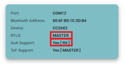
Hardware settings:
In this case, the passive device is not required. The BOOSTXL-AoA must be on the master device.
Embedded Software settings:
In theory, no modification is required by the out-of-the-box software to run the demo. The guidance are provided for training purposes only.
rtls_passive: As previously said, the passive device is not required (no need to turn it on or to flash any image on it).rtls_master: The master's RTLS Control module needs the capability to act as RTLS Master and AoA receiver. This capabilities are set modifying (if needed) the fieldrtlsCapabof thertlsConfigstructure (this must be done into themain.cfile which is stored under theStartupfolder). The capabilities we need for the lab are onlyRTLS_CAP_RTLS_MASTERandRTLS_CAP_AOA_RX.rtlsConfig.rtlsCapab = (rtlsCapabilities_e)(RTLS_CAP_RTLS_MASTER | RTLS_CAP_AOA_RX);main.c::main()
Note: The python script configures the master device in order to select the appropriate antennas and switching pattern. The default parameters are as following:
"aoa_cc26x2": {
  "aoa_slot_durations": 1,
  "aoa_sample_rate": 1,
  "aoa_sample_size": 1,
  "aoa_sampling_control": int('0x10', 16),
  ## bit 0   - 0x00 - default filtering, 0x01 - RAW_RF no filtering,
  ## bit 4,5 - default: 0x10 - ONLY_ANT_1, optional: 0x20 - ONLY_ANT_2
  "aoa_sampling_enable": 1,
  "aoa_pattern_len": 3,
  "aoa_ant_pattern": [0, 1, 2]
}
aoa_params used by default by the python script
rtls_slave: Ensure the slave's RTLS Control module has the capability to act as a slave (RTLS_CAP_RTLS_SLAVE) and to send out the CTE (RTLS_CAP_AOA_TX).rtlsConfig.rtlsCapab = (rtlsCapabilities_e)(RTLS_CAP_RTLS_SLAVE | RTLS_CAP_AOA_TX);main.c::main()
Once you have done the required modification on the embedded code, flash the LaunchPads and power-cycle them
RTLS UI settings:
Run the RTLS UI as explained before. Only the Master is supposed to be connected to the computer. As a result, only the Master device is supposed to be detected by the RTLS UI.
Verify if the master's capabilities listed by the RTLS UI match the settings you have previously done.
Now, test your setting
Same procedure as what we did previously
If AoA values are inaccurate...
Keep in mind that an office environment is not suitable for AoA evaluation. Many metallic and RF reflective surfaces are around you and provoke multipath. Try to find a more open environment.
AoA inaccuracies might also be caused by a bad antenna connection. Verify that the C51 capacitor of your LaunchPad is correctly positioned.
Task 2 – Modify AoA application to use the other antenna array
Using the python scripts...
From now on the lab only gives the direction on how to modify the
python scripts. To keep it simple, we will always use rtls_example_with_rtls_util.py
but the same procedure applies for all the python scripts.
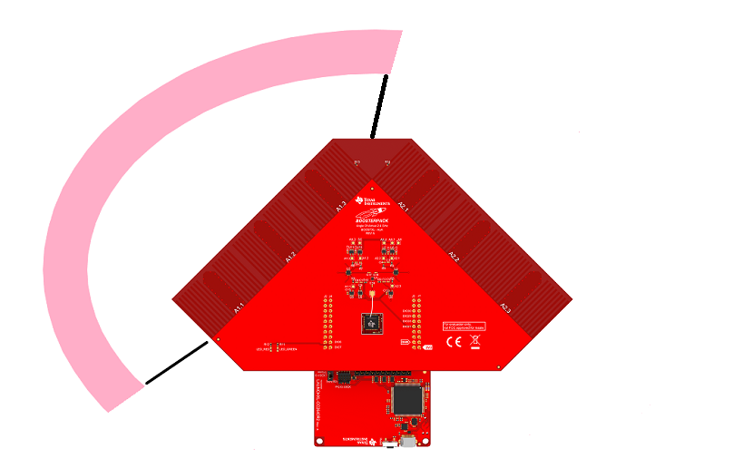
The out of box SimpleLink CC13X2-26X2 SDK example will always use the first antenna array.
We will go from this configuration (using antenna array #1):
To this configuration (using antenna array #2):
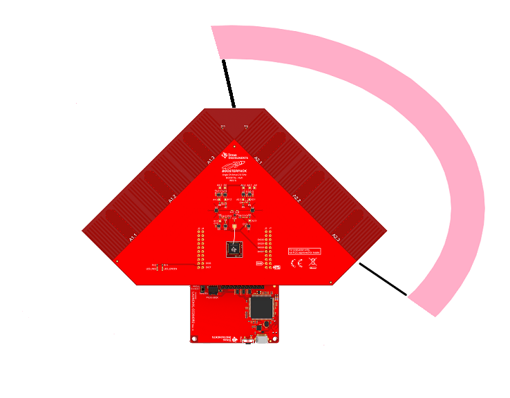
In the python script, modify the aoa_params structure as followed:
    "aoa_cc26x2": {
        "aoa_slot_durations": 1,
        "aoa_sample_rate": 1,
        "aoa_sample_size": 1,
        "aoa_sampling_control": int('0x20', 16),
        ## bit 0   - 0x00 - default filtering, 0x01 - RAW_RF no filtering,
        ## bit 4,5 - default: 0x10 - ONLY_ANT_1, optional: 0x20 - ONLY_ANT_2
        "aoa_sampling_enable": 1,
        "aoa_pattern_len": 3,
        "aoa_ant_pattern": [3, 4, 5]
    }
aoa_params used to activate the second antenna array
Now, test your setting
You have two options available:
Use the same procedure as described previously. In the log you should observe that the antenna 2 is used.
Have a look at DIO27, DIO28, DIO29, DIO30. The antenna switching is controlled by DIO27 to DIO30. Using a logic analyzer, you can determine which antennas are used. The following truth table gives the control logic of the antennas of the BOOSTXL-AoA:
| DIO27 | DIO28 | DIO29 | DIO30 | Antenna Used |
|---|---|---|---|---|
| 0 | 1 | 0 | 0 | A2.1 |
| 0 | 0 | 1 | 0 | A2.2 |
| 0 | 0 | 0 | 1 | A2.3 |
| 1 | 1 | 0 | 0 | A1.1 |
| 1 | 0 | 1 | 0 | A1.2 |
| 1 | 0 | 0 | 1 | A1.3 |
*0: 0.0V to 0.2V, 1: 2.5V to 5.0V
Task 3 – Modify AoA application to use only two antennas
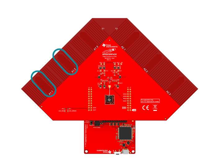
We will use the out of the box example as the baseline and make the proper changes so we only use 2 antennas from the antenna array 1.
Out of the box software is using all 3 antennas from
A1: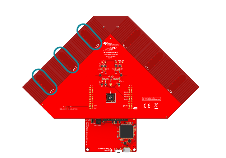
And the end goal is using the following:
The antenna toggling pattern is controlled by radio core, therefore the pattern and the pins are passed on to radio core through override list.
More information!
Even though the radio core does the antenna toggling, the application layer is still responsible to initialize the pins to the correct configuration and the array switch if the feature is required.
The pin initialization is taken care in AOA.c::AOA_initAntArray.
In the python script, modify the aoa_params structure as followed:
    "aoa_cc26x2": {
        "aoa_slot_durations": 1,
        "aoa_sample_rate": 1,
        "aoa_sample_size": 1,
        "aoa_sampling_control": int('0x10', 16),
        ## bit 0   - 0x00 - default filtering, 0x01 - RAW_RF no filtering,
        ## bit 4,5 - default: 0x10 - ONLY_ANT_1, optional: 0x20 - ONLY_ANT_2
        "aoa_sampling_enable": 1,
        "aoa_pattern_len": 2,
        "aoa_ant_pattern": [0, 1]
    }
aoa_params used to activate the second antenna array
Fundamental done
Now the application only uses antenna A1.1 and A1.2! Very well done!
Task 4 – Export raw IQ samples to CSV file
Python solution
The goal of this task is to understand how the script
rtls_aoa_iq_with_rtls_util_export_into_csv.py (stored in your SDK
under tools\ble5stack\rtls_agent\examples)is made.
We will guide you step by step in order to rewrite it. You can directly
jump to the next task if you are not interested in this part...
however it is always cool to discover how the magic happens :)
1- Where does the I/Q Samples come from?
So far we have worked on the application code to modify the
rtls_passive and/or the rtls_master to work with custom HW.
We will now spend some time looking into the I/Q data.
The reason for checking I/Q data is that different HW design will yield different result which will affect your own angle calculation algorithm. For example, if the rf switches you are using need longer settling time than the ones on BOOSTXL-AoA, then you will need to discard more I/Q samples when doing calculations.
To decide how many I/Q samples you can use, you will need to extract I/Q samples and calculate phase to determine at which samples antennas are changing.
We will first take a look at where I/Q samples are stored, in what format and how they are accessed.
For the Passive device
I/Q is stored in the radio core RAM(
RFC_CTE_RFE_RAM_DATA) and each I/Q pair takes up 32 bits space where I is stored in the lower 16 bits and Q is stored in higher 16 bits.void AOA_getRfIqSamples(RF_Handle rfHandle, RF_CmdHandle cmdHandle, RF_EventMask events) { uint8_t state = 0; uint8_t lastCapture; uint32_t *cteData; uint32_t *extCteData = NULL; if (events & RF_EventCmdDone) { lastCapture = HWREGB(RFC_CTE_LAST_CAPTURE); // check which RAM is capturing samples if ((lastCapture == RFC_CTE_CAPTURE_RAM_MCE) || (lastCapture == RFC_CTE_CAPTURE_RAM_RFE)) { // wait while buffer is busy do { state = (lastCapture == RFC_CTE_CAPTURE_RAM_MCE)?HWREGB(RFC_CTE_MCE_RAM_STATE):HWREGB( RFC_CTE_RFE_RAM_STATE); } while ((state == RFC_CTE_RAM_STATE_BUSY) || (state == RFC_CTE_RAM_STATE_DUAL_BUSY)); // check if buffer is ready for reading if ((state == RFC_CTE_RAM_STATE_READY) || (state == RFC_CTE_RAM_STATE_DUAL_READY)) { if (lastCapture == RFC_CTE_CAPTURE_RAM_MCE) { // get the MCE buffer address cteData = (uint32_t *)RFC_CTE_MCE_RAM_DATA; extCteData = (uint32_t *)RFC_CTE_RFE_RAM_DATA; } else { // get the RFE buffer address cteData = (uint32_t *)RFC_CTE_RFE_RAM_DATA; } // This will trigger the upper layer which polls samplesReady if (cteData != NULL && extCteData == NULL) { memcpy(gAoaReport.samples, cteData, AOA_RES_MAX_SIZE * sizeof(AoA_IQSample)); gAoaReport.sampleState = SAMPLES_READY; } // release the RAM so it should be available for next CTE if (lastCapture == RFC_CTE_CAPTURE_RAM_MCE) { HWREGB(RFC_CTE_MCE_RAM_STATE) = RFC_CTE_RAM_STATE_EMPTY; } else { HWREGB(RFC_CTE_RFE_RAM_STATE) = RFC_CTE_RAM_STATE_EMPTY; } } } } // If we don't have samples at this point then they are not valid if (gAoaReport.sampleState != SAMPLES_READY) { gAoaReport.sampleState = SAMPLES_NOT_VALID; } }AOA.c
In
rtls_passive, the functionAOA_getRfIqSamplesis executed (more or less directly) by the functionAOA_postProcess(which is itself called byRTLSCtrl_postProcessAoa, i.e. at the end of each connection event).For the Master device
For the master device, the BLE stack is responsible for reading the I/Q samples from the radio core. The tables containing the I/Q samples (or at least pointers on them) are sent back by the BLE Stack through messages stored in the ICall queue. The message containing I/Q samples are handled by the function
RTLSMaster_processRtlsSrvMsg(inrtls_master.c). This leads to the execution of the functionRTLSCtrl_aoaResultEvt(inrtls_ctrl.c) which in turn enqueues a message of typeAOA_RESULTS_EVENTin the RTLS message-queue.Finally (and as it is done on the passive's side) the
AOA_RESULTS_EVENTtriggers the functionAOA_postProcess. The master does not execute the functionAOA_getRfIqSamples(the I/Q samples are part of thepEvtstructure passed toAOA_postProcess).
I/Q samples resolution
I and Q samples only have 13 bits resolution even though they occupy 16 bits space in radio core RAM (this applies for both the passive and the master devices). Since they only have 13 bits resolution, the maximum and minimum value you will observe as signed integers are [4095, -4096].
2- How to send the I/Q samples to the computer?
If you haven't done it yet, change the COM port used by the script. Of course, if you are not using the passive device, you can comment the corresponding line.
 {"com_port": "COM12", "baud_rate": 460800, "name": "CC26x2 Master"},
 {"com_port": "COM14", "baud_rate": 460800, "name": "CC26x2 Passive"},
Set up the COM ports used
To extract the I/Q data from embedded devices over UART, we need to make sure that we have enough time to flush the I/Q data before next AoA packet arrives.
To achieve this, there are two options:
Increase the connection interval (it is what we are going to do in this lab). In the
rtls_masterreadme file, it's mentioned that the connection interval should be larger than 300ms to accommodate outputting all the samples.Increase the UART baudrate.
For SDK 3.30 and latter, the default UART baudrate is set to 460800. This value is set and can be modified in the function
RTLSHost_openHostIf(in the filertls_host_npi.c, stored in the folderRTLSCtrl.)npiPortParams.portParams.uartParams.baudRate = 921600;Change baudrate (for example) to 921600
Note: The procedure is the same for both passive and master.
If you modify the baudrate in the embedded code, don't forget to modify the baudrate used by the python script to communicate with the devices...
    {"com_port": "COM12", "baud_rate": 921600, "name": "CC26x2 Master"},
    {"com_port": "COM14", "baud_rate": 921600, "name": "CC26x2 Passive"},
Set up the baudrates used
In this lab we will increase connection interval to 500ms and leave the baudrate as is.
→ Change the
connect_interval_mSecparameter to the following code inrtls_example_with_rtls_util.py.connect_interval_mSec = 500 #100Set up connection interval to be 500ms
Post Processing on Embedded Device
For users that will do I/Q data post process on chip, there is no limitation on the connection interval.
Now we will build on top of the python script that is used in running the RTLS non-visual demo
First we create a csv file to store I/Q data for analyzing later if needed. Normally, this code is already written in your
rtls_aoa_iq_with_rtls_util_export_into_csv.pyfile, in the functioninitialize_csv_file. This function assumes that you have properly imported the csv package and declared the global variables csv_writer and csv_row. You can change thefilenameto whichever suits you better.global csv_writer global csv_row # Prepare csv file to save data data_time = datetime.datetime.now().strftime("%m_%d_%Y_%H_%M_%S") filename = f"{data_time}_rtls_raw_iq_samples.csv" outfile = open(filename, 'w', newline='') csv_fieldnames = ['pkt', 'sample_idx', 'rssi', 'ant_array', 'channel', 'i', 'q'] csv_row = namedtuple('csv_row', csv_fieldnames) csv_writer = csv.DictWriter(outfile, fieldnames=csv_fieldnames) csv_writer.writeheader()Create a csv file to log I/Q data
The devices must be reseted, then the master can scan and connect
     ## Reset the passive and the master
     rtlsUtil.reset_devices()

     ##...

     ## Ask the master to scan
     scan_results = rtlsUtil.scan(scan_time_sec)

     ##...

     ## Ask the master to connect a device
     rtlsUtil.ble_connect(scan_results[0], connect_interval_mSec)
Set the parameter to configure the devices
Once the slave and the master are connected, we can start the setup of AoA parameters
To extract I/Q data, the AoA operation mode needs to be
AOA_MODE_RAW. If needed, modify in the aoa_params structure, modify the aoa_run_mode to the following:aoa_params = { "aoa_run_mode": "AOA_MODE_RAW", ## AOA_MODE_ANGLE, AOA_MODE_PAIR_ANGLES, AOA_MODE_RAW "aoa_cc2640r2": { "aoa_cte_scan_ovs": 4, "aoa_cte_offset": 4, "aoa_cte_length": 20, "aoa_sampling_control": int('0x00', 16), ## bit 0 - 0x00 - default filtering, 0x01 - RAW_RF no filtering - not supported, ## bit 4,5 - 0x00 - default both antennas, 0x10 - ONLY_ANT_1, 0x20 - ONLY_ANT_2 }, "aoa_cc26x2": { "aoa_slot_durations": 1, "aoa_sample_rate": 1, "aoa_sample_size": 1, "aoa_sampling_control": int('0x10', 16), ## bit 0 - 0x00 - default filtering, 0x01 - RAW_RF no filtering, ## bit 4,5 - default: 0x10 - ONLY_ANT_1, optional: 0x20 - ONLY_ANT_2 "aoa_sampling_enable": 1, "aoa_pattern_len": 3, "aoa_ant_pattern": [0, 1, 2] } }Set the parameter to configure the devices
Let's have a look to the mode that used after a BLE connection has been established. Basically, the data are written to the .csv file until a STOP command is received.
     try:
         data = q.get(block=True, timeout=0.5)
         if isinstance(data, dict):
             data_time = datetime.datetime.now().strftime("[%m:%d:%Y %H:%M:%S:%f] :")
             print(f"{data_time} {json.dumps(data)}")

             offset = data['payload'].offset
             payload = data['payload']

             # If we have data, and offset is 0, we are done with one dump
             if offset == 0 and len(dump_rows):
                 pkt_cnt += 1

                 # Make sure the samples are in order
                 dump_rows = sorted(dump_rows, key=lambda s: s.sample_idx)

                 # Write to file
                 for sample_row in dump_rows:
                     csv_writer.writerow(sample_row._asdict())

                 # Reset payload storage
                 dump_rows = []

             # Save samples for writing when dump is complete
             for sub_idx, sample in enumerate(payload.samples):
                 sample = csv_row(pkt=pkt_cnt, sample_idx=offset + sub_idx, rssi=payload.rssi,
                                    ant_array=payload.antenna, channel=payload.channel, i=sample.i, q=sample.q)
                 dump_rows.append(sample)

         elif isinstance(data, str) and data == "STOP":
             print("STOP Command Received")

             # If we have data, and offset is 0, we are done with one dump
             if len(dump_rows):
                 # Make sure the samples are in order
                 dump_rows = sorted(dump_rows, key=lambda s: s.sample_idx)

                 # Write to file
                 for sample_row in dump_rows:
                     csv_writer.writerow(sample_row._asdict())

             break
         else:
             pass
     except queue.Empty:
         continue
Script's main loop (in results_parsing subfunction)
Log file
By default, the script produces a log file. This file is stored in the same path as the .csv file (i.e. in the directory from where the script was run) and can be useful for debug.
After running the script, you can see the following format in the csv file.
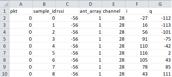
Remark 1: The names of the columns are chosen when the CSV is initialized.
 csv_fieldnames = ['pkt', 'sample_idx', 'rssi', 'ant_array', 'channel', 'i', 'q']
 csv_row = namedtuple('csv_row', csv_fieldnames)

 csv_writer = csv.DictWriter(outfile, fieldnames=csv_fieldnames)
 csv_writer.writeheader()
Remark 2: The data written in each column are chosen by the following code.
 # Samples are prepared
 sample = csv_row(pkt=pkt_cnt, sample_idx=offset + sub_idx, rssi=payload.rssi,
                    ant_array=payload.antenna, channel=payload.channel, i=sample.i, q=sample.q)
 dump_rows.append(sample)

 #...

 # Samples are written to the CSV file latter
 for sample_row in dump_rows:
     csv_writer.writerow(sample_row._asdict())
3- How to treat the I/Q samples on the computer?
Here we are only interested in the payload part of the AOA_MODE_RAW command. The AOA_MODE_RAW payload has the following structure. In the python script provided above, we have extracted most of the information and save them to a csv file.
  struct = Struct(
      "rssi" / Int8sl,
      "antenna" / Int8ul,
      "channel" / Int8ul,
      "offset" / Int16ul,
      "samplesLength" / Int16ul,
      "samples" / GreedyRange(Struct(
          "q" / Int16sl,
          "i" / Int16sl,
      )),
  )
ss_rtls.py::class AoaResultRaw
New Python Packages
For the script below you will have to install the following new Python packages
- pandas
- matplotlib
They can be installed with pip. Consult the running the RTLS non-visual demo chapter for more information on how to install packages from pip.
import matplotlib.pyplot as plt
import pandas as pd
import math
def cal_magnitude(q_value,i_value):
return math.sqrt(math.pow(q_value,2)+math.pow(i_value,2))
def cal_phase(q_value,i_value):
return math.degrees(math.atan2(q_value,i_value))
if __name__ == "__main__":
df = pd.read_csv('sla_rtls_raw_iq_samples.csv')
AOA_RES_MAX_SIZE=81
# We only want one set of data per channel
df = df.drop_duplicates(subset=['channel','sample_idx'] , keep='first')
# We Calculate the phase and the margin
df['phase'] = df.apply(lambda row: cal_phase(row['q'], row['i']), axis=1)
df['magnitude'] = df.apply(lambda row: cal_magnitude(row['q'], row['i']), axis=1)
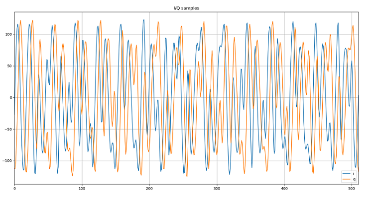
# Plot all the I/Q collected. Each channel will have a plot which contains I/Q samples.
# If you have collected I/Q data on 37 data channels, then there will be 37 windows popped up
grouped = df.groupby('channel')
grouped[['i', 'q']].plot(title="I/Q samples", grid=True)
plt.show()
# Create 4 plots and each plot has x number of subplots. x = number of channels
indexed = df.set_index(['channel', 'sample_idx'])
indexed.unstack(level=0)[['phase']].plot(subplots=True, title="Phase information", xlim=[0,AOA_RES_MAX_SIZE], ylim=[-190,+190])
indexed.unstack(level=0)[['magnitude']].plot(subplots=True, title="Signal magnitude", xlim=[0,AOA_RES_MAX_SIZE])
indexed.unstack(level=0)[['i']].plot(subplots=True, title="I samples", xlim=[0,AOA_RES_MAX_SIZE])
indexed.unstack(level=0)[['q']].plot(subplots=True, title="Q samples", xlim=[0,AOA_RES_MAX_SIZE])
plt.show()
This script can be executed as is.
After executing the small script provided above, if the angle between rtls_passive
rtls_slave is not 0 degree, you can see that magnitude of the sine wave is not the same
when you swap between antenna 1 and antenna 2 as shown below.
Another alternative to observe the magnitude of received signal is to calculate it based on I/Q data. Since each I/Q pair is a vector, the magnitude of a vector can be calculated by sqrt(I^2+Q^2).
Using the script provided above, you will see a plot called Signal magnitude. In this plot, you can clear see that received signal magnitude from antenna 2 is almost double as from antenna 1.
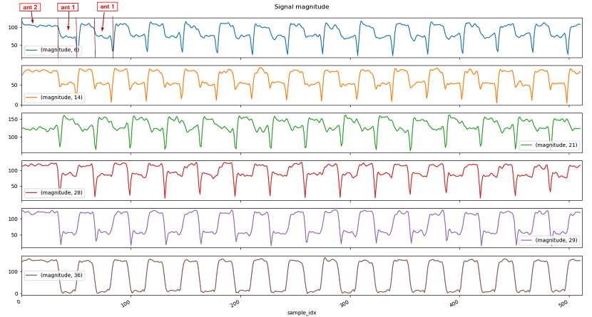
More information!
If there is no antenna toggling, then the I/Q samples will form a perfect sine wave. To prove it, change the antenna toggling pattern from 2 antennas to 1 antenna(A1.2), and see how the I/Q plots look like.
Task 5 – Antenna Switch Settling Time
Now that we are equipped with all the needed tools to manipulate I/Q data, we will try to identify when the antenna is toggling in order to help determine which I/Q samples can be used.
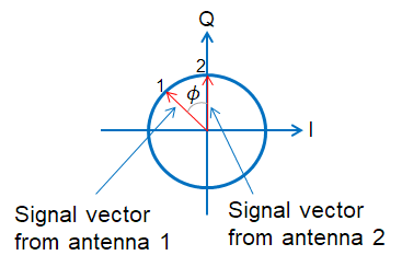
As mentioned in Calculate the phase difference among the antennas, I/Q samples can be presented with constellation diagram, each I/Q pair is a vector and its angle is within a range of +180 ~ -180. Therefore when we have an I/Q pair, to obtain the angle information, we can use arctan to get angle of a vector. Then based on the I and Q value, we can find out the corresponding angle.
| I > 0 | I < 0 | |
|---|---|---|
| Q >=0 | angle = arctan(Q/I) | angle = 180 + arctan(Q/I) |
| Q < 0 | angle = arctan(Q/I) | angle = -180 + arctan(Q/I) |
Luckily in python, the math.atan2 function takes care of the aforementioned logic.
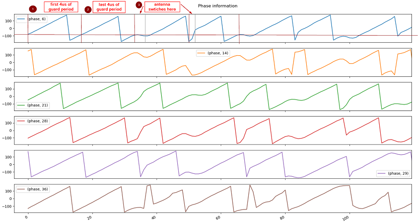
Let's take a look at the Phase Information plot.
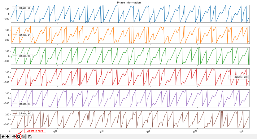
A perfect sine wave, assuming it starts at 0 degree, the phase will first go towards +180 and then, once it crosses +180, it will start from -180 and then go back to 0 degrees. From the picture provided below, you can see that in the first 8us(32 samples), there is no abrupt phase change.
When the rf switches and the angle of incident wave is not 0 degree, you will see abrupt phase change. As shown below after 2 periods, we started to switch antennas. Then the phase we obtained is no long linear.
Hence by looking at the phase information plot, you will know how many I/Q samples you can keep per period.
That's all folks!
You earned a coffee ☕.
Now go off and make something awesome with Angle Of Arrival!
This work is licensed under a Creative Commons Attribution-NonCommercial-NoDerivatives 4.0 International License.