Introduction
This workshop will show you how to create and integrate a basic Sensor Controller ADC driver with a blank TI-RTOS project. The training is expected to take about 2 h to complete. There should be at least an beginner level of knowledge of the C programming language as well experience with embedded software development to be able to complete the tasks.
The Sensor Controller ADC driver will measure an analog input voltage on one pin (DIO29) and set the green LED if the input ADC value is below a set threshold to indicate LOW input. If the ADC input value is above the set threshold it will notify the main application processor which then set the Red LED to indicate HIGH input. To vary the input voltage applied to the pin, an external voltage source can be connected to the analog input pin. In this workshop a jumper from the LaunchPad is used to short the analog input pin with adjacent pins (DIO28 and DIO30). There are two additional bonus tasks: one for Bluetooth® low energy and one for proprietary operation. Refer to the table below to find the required HW for each bonus task.
Compatible Connected MCU LaunchPad kits
This workshop can be completed with any one of the SimpleLink™ Wireless MCU with Sensor Controller devices described in the table below. Install the required Associated SimpleLink Software Development Kit matching your device. For more details on LaunchPads please visit the LaunchPad overview page.
Abbreviations / terminology
| Abbreviation / terminology | Definition |
|---|---|
| CCS | Code Composer Studio |
| SC | Sensor Controller |
| SCS | Sensor Controller Studio |
| AUX RAM | Sensor Controller Memory |
| RTC | Real-Time Clock |
| RTOS | Real-Time Operating System |
| TI-RTOS | RTOS for TI microcontrollers |
| SDK | Software Development Kit |
| S-W-MCU | SimpleLink Wireless Micro Controller Unit |
Prerequisites
Completed material
- Sensor Controller Basics - Getting Started
- TI-RTOS Basics Lab 1
- For Bonus Task 1: Bluetooth Low Energy Fundamentals workshop
- For Bonus Task 2: Proprietary RF – Basic RX and TX
Software for desktop development
In order to start with this exercise you will need to download the correct Software Development Kit (SDK) for your LaunchPad. This training covers the CC13x0, CC13x2, CC2640R2 and the CC26x2 device families.
| Device | SDK downloads |
|---|---|
| CC13x0 | SimpleLink CC13x0 Software Development Kit |
| CC2640R2 | SimpleLink CC2640R2 Software Development Kit |
| CC13x2/ CC26x2 | SimpleLink CC13x2/ CC26x2 Software Development Kit |
Except for the relevant SDK for your choice of Launchpad, you also need the following software:
The following software applies for all device families:
Code Composer Studio version 9.2 or later
Make sure that CCS is using the latest updates: Help → Check for UpdatesSensor Controller Studio version 2.5.0 or later
For Bonus Task 1:
- Bluetooth mobile app:
- Android: BLE Scanner by Bluepixel Technology LLP - available on the Google Play store
- iOS: LightBlue Explorer - Bluetooth Low Energy by Punch Through - available on the App Store
OR
- BTool (located in tools/blestack directory of the SimpleLink SDK installation)
- Bluetooth mobile app:
- For Bonus Task 2:
- SmartRF Studio 7 version 2.13.0 or higher
Hardware
One LaunchPad connected with a USB micro cable:
- LAUNCHXL-CC1310,
- LAUNCHXL-CC1312R1,
- LAUNCHXL-CC1350,
- LAUNCHXL-CC1352R1,
- LAUNCHXL-CC1352P,
- LAUNCHXL-CC26x2R1, or
External variable voltage source or wire/jumper.
For bonus task1:
- One CC2640R2F LaunchPad
- Mobile device for testing or any other Bluetooth client applications as described in Bluetooth Low Energy Fundamentals workshop
For bonus task2:
- Two CC13xx LaunchPads.
Getting started – Desktop
Install the software
1 - Run the Associated SDK installer (refer to table in
introduction) to the default directory:
C:\ti\
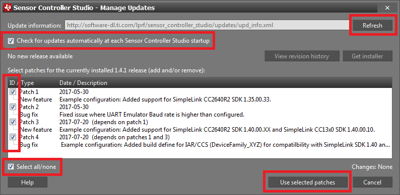
2 - Install Sensor Controller Studio and enable all patches. Patches
can be enabled by first clicking Updates → Check for Updates. If any
new patches are available, click Updates → Manage Updates... and
apply all new patches. Note that the picture below is only used as an example.
You may have a newer version, and there may be no patches available.
Getting started – Hardware
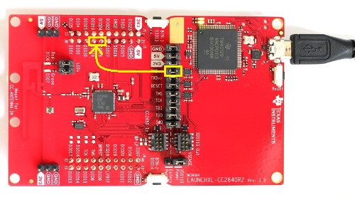
Connect the LaunchPad to your computer via the micro-USB cable. DIO29 on
LaunchPad will be the ADC input. Connect the external variable voltage source
to DIO29. As an alternative, a jumper or wire can be used. In this training
DIO29 is connected to DIO28 or DIO30 via a jumper, borrowed from RXD<<
on the LaunchPad. DIO28 will be set as digital output HIGH and DIO30 as
digital output LOW, which will be used to test and verify the ADC driver and
main application. Note that any jumper that does not interfere with the
application can be used. See picture below for reference.
Task 1 – Import, build and download clean TI-RTOS Project
In this task you will import a clean TI-RTOS Driver project called Empty and
run the program on your LaunchPad. This project will be used as a clean
template to integrate the SC driver. It is a minimal TI-RTOS example project
that has one single task that toggles the red LED on the LaunchPad once every
second.
- In CCS, go to Project &rdash; Properties, or press Alt+Enter.
- Click on
Buildsection to the left. - Navigate to the
Variablestab. - Click on
Show system variablescheckbox at the bottom. - Scroll down until you find the
WORKSPACE_LOCvariable, and note the value. This is your CCS workspace path for your project.
Do the following:
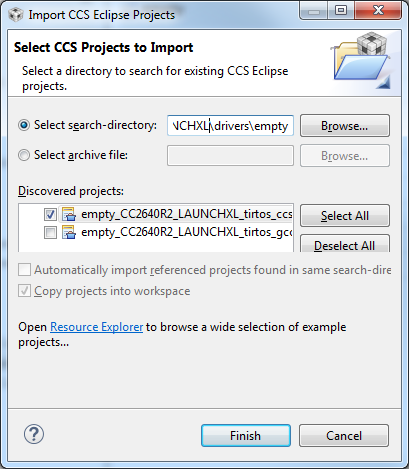
Open CCS and press Project → Import CCS Project
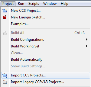
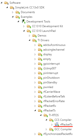
Import the
EmptyProject found in your SDK install path folder subdirectory as shown below:<SDK>\examples\rtos\CCxxxx_LAUNCHXL\drivers\empty
- Build and download the project to your LaunchPad by pressing F11. Then press F8 to allow the program to run. The red LED should now toggle once every second.
If you failed to download and run the "Empty" Project
- Make sure you have connected the LaunchPad to your computer with a micro-USB Cable.
Make sure that you have selected the correct project, e.g.
- called
empty_CC2640R2_LAUNCHXL_tirtos_ccsfor CC2640R2F. - called
empty_CC1352R1_LAUNCHXL_tirtos_ccsfor CC1352R1. - etc.
- called
Unplug and plug in the USB cable again.
- If this fails, you can try to run a "Erase Entire Flash" operation with UniFlash and retry.
Task 2 – Create and setup SCS project
In this task we will create a new Sensor Controller project in SCS.
SCS Documentation and Help
At any time in SCS, Help – Sensor Controller Studio Help or press F1 for documentation and help.
Create SCS project
Do the following:
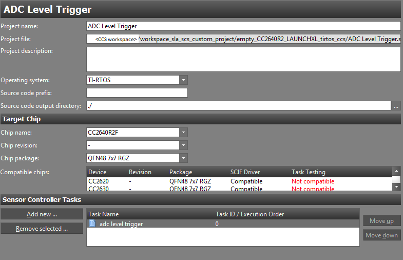
- Start SCS and open a new project, File → New Project or Ctrl+N.
- Set the
Project NametoADC Level Trigger. - Set the
Operating systemtoTI-RTOS. - Set
Source code output directoryto./. - Set
Chip namecorresponding to the device in use, e.g.:CC2640R2Fif using CC2640R2F.CC1352R1F3if using CC1352R1.
- Set
Chip packagetoQFN48 7x7 RGZ. - Add one task by clicking
Add new, name itadc level trigger. - Save the project, File → Save Project or Ctrl+S, to the CCS project base folder in your CCS workspace. See Task 1 on how to find your CCS workspace path.
Correct project file save path
The path set in Project file must be the CCS project base folder located
in the CCS workspace.
Refer to the screen shot below for the CC2640R2F LaunchPad.
Setup SC ADC Driver
Task Properties
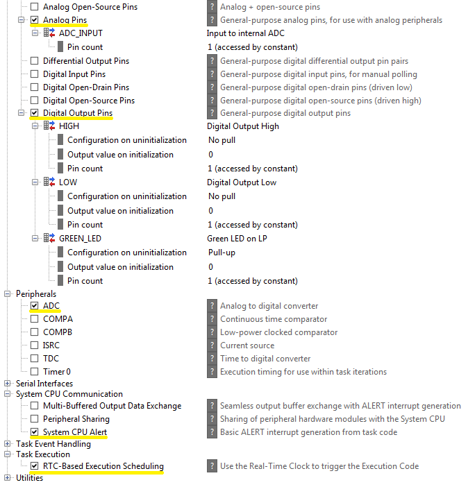
We need to specify the resources to be used. Go to Task Properties for the
adc level trigger task, which can be accessed by clicking on the task name in
the directory on the left hand side, above the Initialization Code. Select
the task resources in the list below.
- Analog Pins
- Create one pin and name it
ADC_INPUT.
- Create one pin and name it
- Digital Output Pins
- Create three pins and name them
GREEN_LED,LOW, andHIGH. You can add more pins by clickingAdd I/O usageto the right of the task resource name.
- Create three pins and name them
- ADC
- System CPU Alert
- RTC-Based Execution Scheduling
Unnecessary pins
If you are using an external variable voltage source connected to the ADC
input, then the two digital pins LOW and HIGH are not needed.
Make sure the Task resource settings match the screenshot below:
I/O mapping
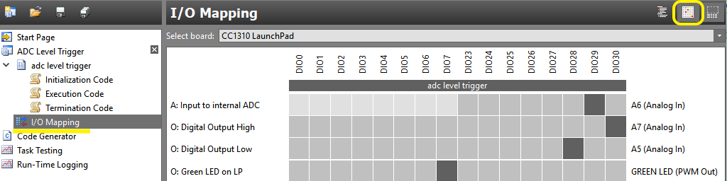
Go to the I/O Mapping window and set the following pins to:
- Analog pin
ADC_INPUTtoDIO29. - Digital pin
GREEN_LEDtoDIO7. - Digital pin
LOWtoDIO28. - Digital pin
HIGHtoDIO30.
The pin order can vary. In the I/O mapping view you can at the top select
which board you are using. For instance, select the CC1310 LaunchPad if you
are using a CC1310 LaunchPad. It should look something like the picture below
if the I/O mapping is displayed in grid mode.
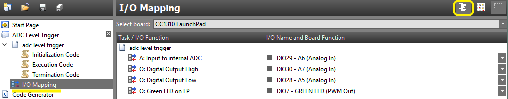
Or, if I/O mapping is displayed in list mode, it should look something like the picture below.
Task 3 – Create Sensor Controller Driver
In this task you will implement and test the ADC driver in Sensor Controller Studio.
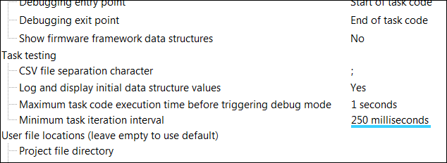
Specify the RTC Trigger Period
The RTC period is specified by Minimum task iteration interval in
preferences, File → Preferences or Ctrl+P. See picture below for
reference. A RTC period of 250 milliseconds is more than enough for this training.
Task testing specific
Specifying the RTC period in SCS only affects the task testing in SCS.
This does not set the RTC period when the SC driver is integrated into other
projects or applications, as this is done through the functions
scifStartRtcTicks() and then started with scifStartRtcTicksNow().
RTC scheduling
The RTC period determines the execution interval of the SC task, if the SC task
is scheduled by the RTC with the fwScheduleTask() function.
fwScheduleTask(N) schedules the next task iteration in N RTC ticks. So for
instance, let's say the RTC is operating at 200Hz. Scheduling the SC task with
fwScheduleTask(1); would run the execution code at a 200Hz rate. With
fwScheduleTask(5); the execution code would run at a (200/5)=40Hz rate, and
so on.
However, to minimize current consumption it is recommended to select the
highest possible tickPeriod so that the argument in fwScheduleTask() can be
as low as possible.
Quiz
If a given SC task is scheduled with fwScheduleTask(2);, and the RTC period
is set to 250 ms, what is the SC task period?
If a SC task period is 700 ms, and the RTC is set at 20 Hz, for which N is
the SC task scheduled with the function fwScheduleTask(N);?
If a SC task is scheduled with fwScheduleTask(3);, and the SC task period is
1500 ms, what is the RTC period?
Adding a data structure member
For a given SC Task, data structure members are used in a SC task to store variables in AUX RAM. This allows the SC Task to store data between task iterations, and to exchange data between the SC and the main application processor. There are four different types of data structures that represent different types of data, shown in the table below. All data structure types have the same format (16 bit word).
| Data structure | Intended use |
|---|---|
| cfg | Configuration of SC Task |
| input | Input data for SC Task |
| output | Output data from SC Task |
| state | Internal state of SC Task |
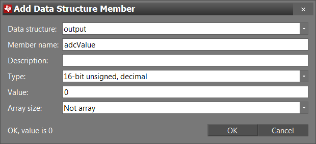
To add a data structure member, locate the Data structures box to the right
in either code window. This is the same for both Initialization Code,
Execution Code, and Termination Code. Click Add. Select which
Data structure, and set Member name and Value. Optionally, but not
necessary, give a Description and choose a Type. See example picture for
ADC output value below.
Quiz
A SC Task is keeping track of how many ADC readings it has done between each task iteration. In which data structure should the variable be placed in?
A SC task is set to notify the main application when a given threshold is crossed, determined by the main application. In which data structure should the threshold be placed in?
Implement the SC ADC driver
It is time to create the ADC driver. The Sensor Controller ADC driver shall measure the analog voltage on DIO28 periodically and set/clear the green LED when the measured input voltage is below/above a set threshold value. The SC will alert the main application when the threshold is crossed, and the main application (TI-RTOS application in this case) will set/clear the red LED if the ADC input value was above/below the threshold.
The threshold is specified by the main application, stored in a cfg structure data member. Being under/above the threshold sets the state to be either low/high. The state is stored in a state structure member. The analog sensor value is sampled by the ADC and stored in an output structure data member.
Create data structure members
You need to create three data structure members: threshold in cfg structure,
adcValue in output structure, and high in state structure. See
Task 3 on how to create data structure
members.
Initialization code
The initialization code will run once when the task is started by the TI-RTOS
application. The initialization code should set the digital values for the
HIGH and LOW pins, select the sampling pin for the ADC, and schedule the
first execution of the execution code to the next RTC tick. See
Task 2 for a more detailed explanation on how RTC
scheduling and how fwScheduleTask() works.
The initialization code is presented below. Copy and paste the code snippet
into the Initialization Code in SCS.
// Set `DIO28` High
gpioSetOutput(AUXIO_O_HIGH);

// Set `DIO30` Low
gpioClearOutput(AUXIO_O_LOW);

// Select ADC input
adcSelectGpioInput(AUXIO_A_ADC_INPUT);

// Schedule the first execution
fwScheduleTask(1);
Initialization code
Execution code
The execution code should enable the ADC, sample and store the ADC value,
compare the converted ADC input value with the threshold, and alert the main
application if a transition happens. As explained in
Task 3, it is scheduled through the
fwScheduleTask() function every RTC tick.
Copy and paste the code snippet below into the Execution Code in SCS.
Note: There is an intentional error in the code, see next section.
// Enable the ADC
adcEnableSync(ADC_REF_FIXED, ADC_SAMPLE_TIME_2P7_US, ADC_TRIGGER_MANUAL);

// Sample the analog sensor
adcGenManualTrigger();
adcReadFifo(output.adcValue);

// Disable the ADC
adcDisable();

U16 oldState = state.high;
if (input.adcValue > cfg.threshold) {
    state.high = 1; // High input - > High state
    gpioClearOutput(AUXIO_O_GREEN_LED);
} else {
    state.high = 0; // Low input -> Low state
    gpioSetOutput(AUXIO_O_GREEN_LED);
}

if (oldState != state.high) {
    // Signal the application processor.
    fwGenAlertInterrupt();
}

// Schedule the next execution
fwScheduleTask(1);
adc level trigger Execution Code
Termination code
The termination code will run once when the SC task is either terminated by the main application, or executed without scheduling. The main purpose for the termination code is to do necessary cleanup.
For this task, there is no necessary cleanup, and the termination code is therefore left empty.
Compilation Error
With the SC driver implemented, it is time for test. However, nobody makes
perfect code. In the execution code above there is a subtle syntax error.
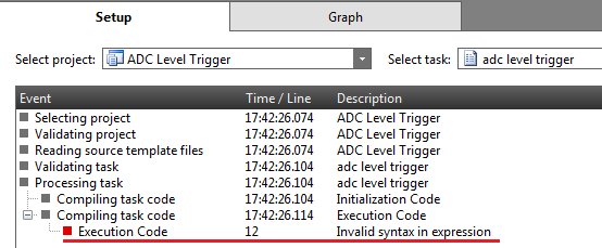
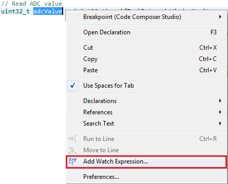
At first glance it's not obvious where the error is, but SCS can help. Go to
the Task Testing window, View → Task Testing or Ctrl+T.
Select the ADC Level Trigger project if this is not already set.
You should now be present with an event log, such as the picture below. It shows the different stages of validating and compiling the project. This event log is only shown in this window when something went wrong during validation and compiling. As we see at the bottom of the log, during compilation of the execution code, it encountered a syntax error at line 12. Note that the line number can vary. See picture below for reference.
So, go back to the execution code window and find the specified line number. If you are observant, you should see that the code line
if (input.adcValue > cfg.threshold) {
is accessing the adcValue from the input structure, and not the
output structure. A subtle bug indeed. Fix the line by changing input to
output.
Now, when going back to the Task Testing window, the event log should no
longer be there and you should be presented with the actual Task Testing
screen.
More code errors?
If you got more syntax errors present, then you might have forgotten to
create or name the pins correctly in the Task Properties window, or to
create or name the data structure members in the code windows. Go back and
double check.
Sensor Controller Task Testing
Now we test the task to verify it works as intended. Do the following:
- Go to the
Task Testingwindow if not already there, View → Task Testing or Ctrl+T. - Select the
ADC Level Triggerproject if not already set. - Select the
Use simplified workflow. See picture below.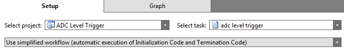
- Add
Run Execution Codeto theTask iteration action sequence.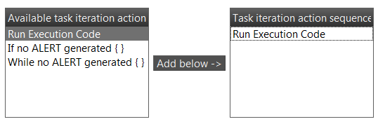
- Click on
ConnectF12. You should now be in the graph tab. If this fails, make sure your LaunchPad is not used by Code Composer Studio.
- On the right side of the graph window you should find all data structure
members created. If there are no variables you might have forgotten to create
them. Configure the
cfg.thresholdvalue by double clicking the variable, set it to 400, and press Enter.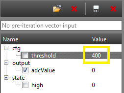
- Then, click
Run Task Iterations ContinuouslyF5.
- Select
output.adcValuein the member struct box. A graph of the variable should appear. - Place the wire or jumper between
DIO29andDIO30. Theoutput.adcValueshould be high andstate.highshould be 1. Now move the wire or jumper betweenDIO28andDIO29. Theoutput.adcValueshould drop down to about 0 andstate.highshould be 0. The green LED should also turn on. See the picture below on what you should observe.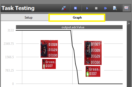
- When you are content that the driver is working, click
DisconnectF11.
Generate Sensor Controller Driver
Now that everything is working well, the next step is to generate the driver from the SCS project.
Do the following:
- Go to the
Code Generatorwindow, View → Code Generator or Ctrl+G. - Select ADC Level Trigger as
Current project. - Either select
Output automaticallyto auto generate code each time visiting the window, or clickGenerate driver source code. - Click
View output directoryand double check it is the project base folder of theEmptyProject. The files should also be visible in the project explorer in CCS, shown in the picture below. Try refreshing the project F5 if they do not show up.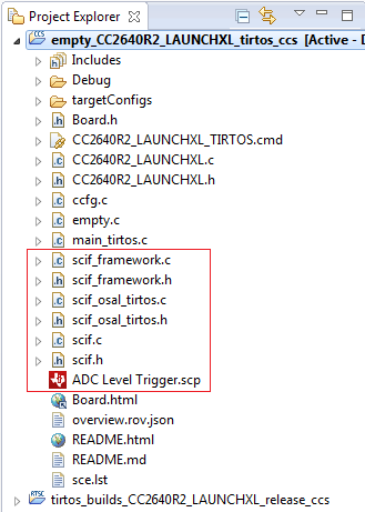
- Build the project and see that it compiles without errors.
SCIF files do not appear in CCS project folder?
If no files are generated during code generation, then the output directory is
most likely wrong. Go back to project settings and make sure Project file and
Source code output directory path are correct. See
Task 2 for help.
Task 4 – Implement TI-RTOS Application
Now we will write the TI-RTOS application and integrate the sensor controller driver you created in Task 3. This task will show you how to communicate with the SC, and the different ways to process the SC data, with focus on execution context.
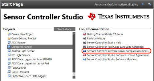
Code documentation regarding the SC can be found at
scif_framework.hfile from code generation.- SC Interface documentation (doxygen), found on the start page.
scif_how_to_use.htmlfile from code generation. This file contains code snippets for most of the topics below with the tasks and variables names used in the SC code.
Refactoring and Cleanup TI-RTOS "empty" Project
Rename the single thread defined in main_tirtos.c called mainThread to a
more descriptive and relevant name for this project. Refactor the function to
tirtosScThread, by right click function and Refactor → Rename..., or click
function and Alt+Shift+R.
TI-RTOS Task and POSIX Thread
The TI-RTOS example use POSIX threads instead of TI-RTOS tasks, but the POSIX thread has an underlying Task object and has support for many of the TI-RTOS kernel task APIs. This workshop will refer to the two terms, thread and task, Interchangeably. To summarize, a POSIX thread in TI-RTOS is practically a TI-RTOS task and a sensor controller task is not related to this as it describes a small program running on the sensor controller. Click here for more info about use of POSIX Thread in TI-RTOS
Also, replace the main loop in the newly renamed tirtosScThread() task with an empty loop while (1) {}.
I/O configuration
The green LED is controlled by the SC. Because of this the TI-RTOS application
GPIO Driver must not initialize and open the green LED pin. To fix this, go to
CCS and comment out the GPIOCCXXXX_DIO_07 line in gpioPinConfigs,
CCxxx0_LAUNCHXL_PIN_GLED line in BoardGpioInitTable and
CCxxx0_LAUNCHXL_GPIO_LED_GREEN in CCxxx0_LAUNCHXL_GPIOName. See code
snippets below for reference (do not copy and paste, but comment out lines with
// or Ctrl+Shift+/).
For example, if you have a CC2640R2 it looks like this, but it is the same steps for every LaunchPad.
GPIO_PinConfig gpioPinConfigs[] = {
    /* Input pins */
    GPIOCC26XX_DIO_13 | ...,  /* Button 0 */
    GPIOCC26XX_DIO_14 | ...,  /* Button 1 */

    /* Output pins */
//  GPIOCC26XX_DIO_07 | ....,  /* Green LED */
    GPIOCC26XX_DIO_06 | ....,  /* Red LED */
};
gpioPinConfigs in CC2640R2_LAUNCHXL.c
const PIN_Config BoardGpioInitTable[] = {
    CC2640R2_LAUNCHXL_PIN_RLED | PIN_GPIO_OUTPUT_EN | ...
//  CC2640R2_LAUNCHXL_PIN_GLED | PIN_GPIO_OUTPUT_EN | ...
    ....
    PIN_TERMINATE
};
BoardGpioInitTable in CC2640R2_LAUNCHXL.c
typedef enum CC2640R2_LAUNCHXL_GPIOName {
    CC2640R2_LAUNCHXL_GPIO_S1 = 0,
    CC2640R2_LAUNCHXL_GPIO_S2,
//  CC2640R2_LAUNCHXL_GPIO_LED_GREEN,
    CC2640R2_LAUNCHXL_GPIO_LED_RED,
    CC2640R2_LAUNCHXL_GPIOCOUNT
} CC2640R2_LAUNCHXL_GPIOName;
CC2640R2_LAUNCHXL_GPIOName in CC2640R2_LAUNCHXL.h
SC driver interaction and processing
There are two aspects with SC interaction and processing that needs to be addressed before implementation: how the SC and main application interact, and how to exchange data.
SC interaction
SC interaction is exclusively intended to be done through the two interrupt
callbacks Control READY and Task ALERT. This way the SC can signal the main
application at appropriate times.
The Control READY interrupt is signaled when one of the non-blocking task
control functions, such as scifStartTasksNbl(), has executed successfully on
the SC. However, the interrupt is encapsulated in the scifWaitOnNbl()
function, and is in most cases, such as this training, not necessary to handle.
The Task ALERT interrupt is signaled when a SC task calls one of the
functions fwGenAlertInterrupt(), fwGenQuickAlertInterrupt() or
fwSwitchOutputBuffer(), as seen done in Task 3.
This interrupt is used to signal the main application when some type of
computation is finished, or some event has happened. This is what is
interesting for us, as this allows us to free the main application from
waiting for the SC driver to finish or some certain SC event to happen.
In the SC initialization part for this project, we handle both signals by
registering a callback for each interrupt. This is only done for the sake of
completeness. As only the Task ALERT signal is of importance for this
project, we are only processing that signal.
Quiz
Which interrupt signal(s) is associated with the task control function
scifStopTasksNbl(), issued from the main application?
Which interrupt signal(s) can a SC Task explicitly generate through procedure calls?
SC task data structure
See Task 3 for an overview of the data structures.
Accessing data stored in the SC AUX RAM can be done in two ways: either direct or indirect access. Which type of access is determined by the type of data structures used: single or multi-buffered. The only requirement is for multi-buffered data, where only indirect access can be used. Single-buffered can use either way. However, direct access is preferred as this is much faster.
Direct access in done through the variable scifTaskData structure, defined in
scif.h. The hierarchy in which the data structure members are stored are as
such: scifTaskData as base, next is the name of the SC task in camelCase,
then the type of the data structure, and lastly the name of the data structure
member.
For instance, the data structure member adcValue, located in the output
structure, defined in the SC task ADC, is accessed as such:
scifTaskData.adcLevelTrigger.output.adcValue. For a complete view of the
scifTaskData structure, see the scif.h file.
The hierarchy and structure of the scifTaskData struct is highly dependent on
the SC task implementation, and will vary from SC driver to SC driver.
Indirect access can be done through the Task data structure access functions
defined in the scif_framework.h file, mainly by the scifGetTaskStruct
function. By specifying the SC Task ID and the structure type, the relevant
structure pointer is returned. As mentioned, this must be used to access
multi-buffered data structures.
Quiz
A data structure member is defined in a SC Task, and is called counter. It is
stored in the output structure. The SC Task is called Pin Counter. What is
the resulting direct access code?
Initialize and setup of SC driver
To initialize and setup the SC driver a couple of necessary steps need to be done. First, add
#include "scif.h"
#define BV(x)    (1 << (x))
Scif header and macro
at the top of the empty.c file. The scif.h file is the main interface to
the SC driver compiled and generated from the SCS project. BV() is a bit
vector macro, which will be useful soon.
Create callback functions
The initialization code for the SC driver uses two callback functions to handle
the two interrupt signals Task ALERT and Control READY. Therefore, copy and
paste the code snippet above the tirtosScThread(), shown below.
void scCtrlReadyCallback(void)
{

} // scCtrlReadyCallback

void scTaskAlertCallback(void)
{

} // scTaskAlertCallback
SC callback functions
Initialize driver and register callbacks
Then, in the tirtosScThread(), before the main loop while(1), copy and
paste the following code snippet. It is important to note that the
initialization code should preferrably be run in a TI-RTOS context, such as a
task context.
// Initialize the Sensor Controller
scifOsalInit();
scifOsalRegisterCtrlReadyCallback(scCtrlReadyCallback);
scifOsalRegisterTaskAlertCallback(scTaskAlertCallback);
scifInit(&scifDriverSetup);

// Set the Sensor Controller task tick interval to 1 second
uint32_t rtc_Hz = 1;  // 1Hz RTC
scifStartRtcTicksNow(0x00010000 / rtc_Hz);

// Configure Sensor Controller tasks
scifTaskData.adcLevelTrigger.cfg.threshold = 600;

// Start Sensor Controller task
scifStartTasksNbl(BV(SCIF_ADC_LEVEL_TRIGGER_TASK_ID));
SC Driver Initialization
So what does the code do? Let's study each code line.
// Initialize the Sensor Controller
scifOsalInit();
scifOsalRegisterCtrlReadyCallback(scCtrlReadyCallback);
scifOsalRegisterTaskAlertCallback(scTaskAlertCallback);
scifInit(&scifDriverSetup);
Driver specific initialization
The first line simply initializes the
OSAL of the scif framework. The next
two lines registers two callbacks for the two interrupt signals Control READY
and Task ALERT from the SC. This is how the main application can communicate
and work together with the SC, explained in the Section
above. The fourth line initializes the SC with our SC task driver created in
Task 3.
// Set the Sensor Controller task tick interval to 1 second
uint32_t rtc_Hz = 1;  // 1Hz RTC
scifStartRtcTicksNow(0x00010000 / rtc_Hz);
RTC initialization
The next line configures the RTC tick interval. This is more thoroughly explained in Task 3.
For this training we are setting the RTC interval to 1 second. However, feel
free to play around with the RTC interval by modifying the rtc_Hz variable or
the function argument directly. The function scifStartRtcTicksNow() takes a
32-bit value as an argument. The argument represents a tick interval, where
bits 31:16 are the seconds, and bits 15:0 are the 1/65536 of a second.
// Configure Sensor Controller tasks
scifTaskData.adcLevelTrigger.cfg.threshold = 600;

// Start Sensor Controller task
scifStartTasksNbl(BV(SCIF_ADC_LEVEL_TRIGGER_TASK_ID));
Task initialization
Next line is the SC task configuration. This part is optional, and can be done
at multiple appropriate times depending on the SC task. We configure the
cfg.threshold variable, just as we did in
Task 3. The SC task configuration can
practically be done at any time in the main application, but is highly
recommended to be done at appropriate times, such as during initialization or
before SC task execution.
The last line starts the actual execution of the SC task. All scif functions
handling task IDs, such as scifStartTasksNbl(), takes a bit vector as an
argument. The macro BV() performs this transformation, and this is why it was
included. The SC Task IDs can be found in the generated scif.h file.
Quiz
Which statement(s) are true?
Implement SC driver application processing
Now we can begin implementing the SC processing. We will do this in increments, implementing it in different application contexts and methods, and at the end discuss the pros and cons for each solution.
All three solutions are interrupt based, where the idea is the same:
- Wait for a
Task ALERTsignal. - Clear the interrupt source.
- Process the SC task.
- Acknowledge the ALERT event to the scif framework.
The actual task processing shall be encapsulated in a function called
processTaskAlert(). Copy and paste the code shown below.
void processTaskAlert(void)
{
    // Clear the ALERT interrupt source
    scifClearAlertIntSource();

    // Do SC Task processing here

    // Acknowledge the ALERT event
    scifAckAlertEvents();
} // processTaskAlert
SC Task Alert Handling
The processing is simple: fetch the state.high variable and copy the value to
the Red LED pin. See Task 4 on how to access SC
data. Copy and paste the code snippet below in processTaskAlert() above,
where the SC task processing is marked.
// Fetch 'state.high' variable from SC
uint8_t high = scifTaskData.adcLevelTrigger.state.high;
// Set Red LED state equal to the state.high variable
GPIO_write(Board_GPIO_RLED, high);
adc level trigger processing
This will not run just yet, as we need to connect the processing to the interrupt signal. Below are the three different solutions presented.
Solution 1 – HWI
For the first solution the SC task alert handling and processing will be done
in the scTaskAlertCallback() function. The scTaskAlertCallback() is
executed in a HWI context, as the title suggests. So in
scTaskAlertCallback(), call the processTaskAlert() function. See code
snippet below.
void scTaskAlertCallback(void)
{
    // Call process function
    processTaskAlert();
} // scTaskAlertCallback
HWI SC Task alert process
Build and debug the project. Move the wire or jumper between DIO28 and
DIO30 on the LaunchPad. You should see the green and red LED toggle
in-between each other.
The application is now doing nothing until the SC task generates a Task ALERT
signal. The HWI callback scTaskAlertCallback() is then called. In the HWI
context the callback clears the interrupt source, read the state variable
state.high, set or clears the red LED, and acknowledges the ALERT event.
Solution 2 – SWI
Doing extensive processing in a HWI process is not advised, as it blocks other high priority processes while running. For this solution, we will move the processing to a SWI process, and the HWI process will signal the SWI process.
At the top of the empty.c file, add the following
#include <ti/sysbios/knl/Swi.h>

// SWI Task Alert
Swi_Struct swiTaskAlert;
Swi_Handle hSwiTaskAlert;

// Function prototype
void processTaskAlert(void);

void swiTaskAlertFxn(UArg a0, UArg a1)
{
    // Call process function
    processTaskAlert();
} // swiTaskAlertFxn
SWI variables and function
In the top of the tirtosScThread task, add the following code snippet to
initialize the SWI process.
// SWI Initialization
Swi_Params swiParams;
Swi_Params_init(&swiParams);
swiParams.priority = 3;
Swi_construct(&swiTaskAlert, swiTaskAlertFxn, &swiParams, NULL);
hSwiTaskAlert = Swi_handle(&swiTaskAlert);
SWI initialization
Now, copy and paste the following into scTaskAlertCallback(). Whenever the
Task ALERT signal is raised, the HWI callback will signal the SWI process,
where the entirety of the processing will be done.
void scTaskAlertCallback(void)
{
    // Post a SWI process
    Swi_post(hSwiTaskAlert);
} // scTaskAlertCallback
SWI signalling
Again, build and debug the project. Move the wire or jumper on the LaunchPad. You should observe the same behavior from the HWI solution.
But why was this whole process of moving the task processing to SWI context necessary if the behavior was the same? This would be much more obvious if the actual task processing was much more extensive computational wise. The current task is substantially small, and therefore will not impact the execution whatever the context it runs in. It is still advised to run the task processing at least in SWI context.
Solution 3 – Task (Thread)
Next solution is to move the processing in a task context. The idea is to signal the main task when the HWI is run, and then in turn run the processing in the task. We will use a Semaphore to synchronize the signaling.
Remove SWI Code
The SWI relevant code, such as the struct and handle variables,
swiTaskAlertFxn() function, and initialization, can now be commented out or
removed. This does not include the processTaskAlert() function.
First up, at the top of the empty.c file, add the relevant header file and
variables.
#include <ti/sysbios/knl/Semaphore.h>
#include <ti/sysbios/BIOS.h>


// Main loop Semaphore
Semaphore_Struct semMainLoop;
Semaphore_Handle hSemMainLoop;
Semaphore variables
Next, In the top of the tirtosScThread task, initialize the semaphore struct
and store the handle.
// Semaphore initialization
Semaphore_Params semParams;
Semaphore_Params_init(&semParams);
Semaphore_construct(&semMainLoop, 0, &semParams);
hSemMainLoop = Semaphore_handle(&semMainLoop);
Semaphore initialization
Now, in the scTaskAlertCallback() function, you will post to the Semaphore
which should trigger the execution in the tirtosScThread while-loop.
void scTaskAlertCallback(void)
{
    // Post to main loop semaphore
    Semaphore_post(hSemMainLoop);
} // scTaskAlertCallback
Semaphore signalling
Now in the main loop in tirtosScThread(), we wait on the Semaphore
indefinitely and afterwards call processTaskAlert(), see code snippet below.
while (1) {
    // Wait on sem indefinitely
    Semaphore_pend(hSemMainLoop, BIOS_WAIT_FOREVER);

    // Call process function
    processTaskAlert();
}
tirtosScThread while-loop
Build and debug the project. Move the wire or jumper on the LaunchPad. The same behavior again should be observed. This way of using the HWI process to signal a task process (or a SWI process in solution 2) is the way to go. Not only does it free up high priority processes, but it also streamlines the application processing, which is important in bigger applications.
main_tirtos.c:
/*
 *  ======== main_tirtos.c ========
 */
#include <stdint.h>

/* POSIX Header files */
#include <pthread.h>

/* RTOS header files */
#include <ti/sysbios/BIOS.h>

/* Example/Board Header files */
#include "Board.h"

extern void *tirtosScThread(void *arg0);

/* Stack size in bytes */
#define THREADSTACKSIZE    1024

/*
 *  ======== main ========
 */
int main(void)
{
    pthread_t           thread;
    pthread_attr_t      pAttrs;
    struct sched_param  priParam;
    int                 retc;
    int                 detachState;

    /* Call driver init functions */
    Board_initGeneral();

    /* Set priority and stack size attributes */
    pthread_attr_init(&pAttrs);
    priParam.sched_priority = 1;

    detachState = PTHREAD_CREATE_DETACHED;
    retc = pthread_attr_setdetachstate(&pAttrs, detachState);
    if (retc != 0) {
        /* pthread_attr_setdetachstate() failed */
        while (1);
    }

    pthread_attr_setschedparam(&pAttrs, &priParam);

    retc |= pthread_attr_setstacksize(&pAttrs, THREADSTACKSIZE);
    if (retc != 0) {
        /* pthread_attr_setstacksize() failed */
        while (1);
    }

    retc = pthread_create(&thread, &pAttrs, tirtosScThread, NULL);
    if (retc != 0) {
        /* pthread_create() failed */
        while (1);
    }

    BIOS_start();

    return (0);
}
empty.c:
/*
 *  ======== empty.c ========
 */

/* For usleep() */
#include <unistd.h>
#include <stdint.h>
#include <stddef.h>

/* Driver Header files */
#include <ti/drivers/GPIO.h>
// #include <ti/drivers/I2C.h>
// #include <ti/drivers/SDSPI.h>
// #include <ti/drivers/SPI.h>
// #include <ti/drivers/UART.h>
// #include <ti/drivers/Watchdog.h>

/* Board Header file */
#include "Board.h"

#include "scif.h"
#define BV(x)    (1 << (x))
#include <ti/sysbios/knl/Swi.h>
#include <ti/sysbios/knl/Semaphore.h>
#include <ti/sysbios/BIOS.h>

// Main loop Semaphore
Semaphore_Struct semMainLoop;
Semaphore_Handle hSemMainLoop;

// SWI Task Alert
Swi_Struct swiTaskAlert;
Swi_Handle hSwiTaskAlert;


void processTaskAlert(void)
{
    // Clear the ALERT interrupt source
    scifClearAlertIntSource();

    // Do SC Task processing here
    // Fetch 'state.high' variable from SC
    uint8_t high = scifTaskData.adcLevelTrigger.state.high;
    // Set Red LED to the state variable
    GPIO_write(Board_GPIO_RLED, high);

    // Acknowledge the ALERT event
    scifAckAlertEvents();
} // processTaskAlert


void scCtrlReadyCallback(void)
{

} // scCtrlReadyCallback

void scTaskAlertCallback(void)
{

    // Post to main loop semaphore
    Semaphore_post(hSemMainLoop);

} // scTaskAlertCallback


/*
 *  ======== mainThread ========
 */
void *tirtosScThread(void *arg0)
{

    // Semaphore initialization
    Semaphore_Params semParams;
    Semaphore_Params_init(&semParams);
    Semaphore_construct(&semMainLoop, 0, &semParams);
    hSemMainLoop = Semaphore_handle(&semMainLoop);

    /* Call driver init functions */
    GPIO_init();
    // I2C_init();
    // SDSPI_init();
    // SPI_init();
    // UART_init();
    // Watchdog_init();

    // Initialize the Sensor Controller
    scifOsalInit();
    scifOsalRegisterCtrlReadyCallback(scCtrlReadyCallback);
    scifOsalRegisterTaskAlertCallback(scTaskAlertCallback);
    scifInit(&scifDriverSetup);

    // Set the Sensor Controller task tick interval to 1 second
    uint32_t rtc_Hz = 1;  // 1Hz RTC
    scifStartRtcTicksNow(0x00010000 / rtc_Hz);

    // Configure Sensor Controller tasks
    scifTaskData.adcLevelTrigger.cfg.threshold = 600;

    // Start Sensor Controller task
    scifStartTasksNbl(BV(SCIF_ADC_LEVEL_TRIGGER_TASK_ID));


    while (1) {
        // Wait on sem indefinitely
        Semaphore_pend(hSemMainLoop, BIOS_WAIT_FOREVER);

        // Call process function
        processTaskAlert();
    }
}
Solutions summary
We have now implemented and tested three different solutions.
HWI Context:
This gave us the fastest possible response time, as the actual processing was
done as close to the Task ALERT signal as possible. However, this is never
advised, as any HWI process should be kept to minimal execution time and not
block other high priority processes from executing.
SWI Context: This solution does not have as fast response time as the HWI solution, since the HWI process must signal the SWI process. This is however preferred over the HWI solution, as it does not block other high priority processes.
Task Context: This solution can result in slower response time than the SWI context solution, but does not block other high priority processes. This solution can safely scale with increasingly more complex projects.
Solution two (SWI) is a viable method, but solution 3 (Task) is the preferred solution in most cases. It is flexible as the task priority can be adjusted, scalable with complex projects and can handle computational heavy processing without blocking time-critical high priority processes or interrupts.
Quiz
Which context(s) gives the fastest response time?
Which context(s) are preferred for computational heavy processing?
Which context(s) is the NOT recommended for computational heavy processing?
Bonus Tasks 1 – Integrate with BLE (CC2640R2F, CC13x2 or CC26x2)
In this training, we are porting our simple application into the BLE project
Project Zero. It is meant to show you how the application would operate
within a bigger and more complex project. We are going to use the already
existing service Data Service to communicate the current state of the ADC
input, high or low.
Hardware requirement
For this lab, you need one Bluetooth-enabled development boards. Supported development boards are:
Instructions for CC260R2 and CC13x2/CC26x2 are different. Please select the correct tab below.
Import and modify Project Zero
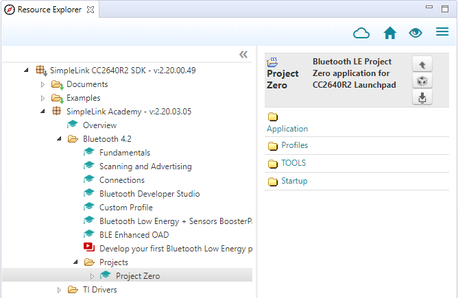
First, import a fresh version of Project Zero. You can use Resource Explorer
in CCS. It can be found in the SimpleLink Academy package, under the Bluetooth
LE section. Expand box below for reference.
Do the following:
Copy and paste (you can drag and drop with the mouse in CCS) all 6
scifrelated code files from theemptyproject into theApplication/folder inProject Zero.Open the
project_zero.cfile.Add
#include "scif.h"at the top.Add
APP_MSG_SC_CTRL_READYandAPP_MSG_SC_TASK_ALERTenum in theapp_msg_types_tenum typedef.Find the
ledPinTable[]array. Comment out theBoard_GLEDmember. Remember that this is the LED that the SC task controls.Add the following function declarations
// Sensor Controller functions
static void scCtrlReadyCallback(void);
static void scTaskAlertCallback(void);
static void processTaskAlert(void);
Sensor Controller Function Declarations
Copy and paste the SC Driver initialization into
ProjectZero_taskFxn().In
user_processApplicationMessage(), add the following case in the switch statement- Note that a case for
APP_MSG_SC_CTRL_READYis not added because it is not needed in this application.
- Note that a case for
case APP_MSG_SC_TASK_ALERT:
  processTaskAlert();
  break;
Sensor Controller Switch Case
- Add the following functions
static void scCtrlReadyCallback(void)
{
  // Notify application `Control READY` is active
  user_enqueueRawAppMsg(APP_MSG_SC_CTRL_READY, NULL, 0);
} // scCtrlReadyCallback

static void scTaskAlertCallback(void)
{
  // Notify application `Task ALERT` is active
  user_enqueueRawAppMsg(APP_MSG_SC_TASK_ALERT, NULL, 0);
} // scTaskAlertCallback

static void processTaskAlert(void)
{
  // Clear the ALERT interrupt source
  scifClearAlertIntSource();

  // Get 'state.high', and set highStr to appropriate string
  uint16_t high = scifTaskData.adcLevelTrigger.state.high;
  char *highStr = (high != 0) ? "HIGH" : "LOW";
  // Set the highStr to the String characteristic in Data Service
  DataService_SetParameter(DS_STRING_ID, strlen(highStr), highStr);

  // Set/clear red LED.
  PIN_setOutputValue(ledPinHandle, Board_GPIO_RLED, high);

  // Acknowledge the ALERT event
  scifAckAlertEvents();
} // processTaskAlert
Sensor Controller Functions
- Build and debug the project. The first build may take a while.
Import and Modify Project Zero
First, import a fresh version of Project Zero. Import it to CCS from the SDK
installation directory: <SDK>\examples\rtos\CC26X2R1_LAUNCHXL\ble5stack\project_zero.
Do the following:
Copy and paste (you can drag and drop with the mouse in CCS) all 6
scifrelated code files from theemptyproject into theApplication/folder inProject Zero.Open the
project_zero.cfile.Add
#include "scif.h"at the top.Add
PZ_SC_CTRL_READYandPZ_SC_TASK_ALERTin the application messages defines list.// Types of messages that can be sent to the user application task from other // tasks or interrupts. Note: Messages from BLE Stack are sent differently. #define PZ_SERVICE_WRITE_EVT 0 /* A characteristic value has been written */ #define PZ_SERVICE_CFG_EVT 1 /* A characteristic configuration has changed */ #define PZ_UPDATE_CHARVAL_EVT 2 /* Request from ourselves to update a value */ #define PZ_BUTTON_DEBOUNCED_EVT 3 /* A button has been debounced with new value */ #define PZ_PAIRSTATE_EVT 4 /* The pairing state is updated */ #define PZ_PASSCODE_EVT 5 /* A pass-code/PIN is requested during pairing */ #define PZ_ADV_EVT 6 /* A subscribed advertisement activity */ #define PZ_START_ADV_EVT 7 /* Request advertisement start from task ctx */ #define PZ_SEND_PARAM_UPD_EVT 8 /* Request parameter update req be sent */ #define PZ_CONN_EVT 9 /* Connection Event End notice */ #define PZ_READ_RPA_EVT 10 /* Read RPA event */ #define PZ_SC_CTRL_READY 11 /* Sensor controller control ready */ #define PZ_SC_TASK_ALERT 12 /* Sensor controller task alert */Add two sensor controller message defines.
Find the
ledPinTable[]array. Comment out theCONFIG_PIN_GLEDmember. Remember that this is the LED that the SC task controls.Add the following function declarations
// Sensor Controller functions
static void scCtrlReadyCallback(void);
static void scTaskAlertCallback(void);
static void processTaskAlert(void);
Sensor Controller Function Declarations
Add the following functions
static void scCtrlReadyCallback(void)
{
  // Notify application `Control READY` is active
    ProjectZero_enqueueMsg(PZ_SC_CTRL_READY, 0);
} // scCtrlReadyCallback

static void scTaskAlertCallback(void)
{
  // Notify application `Task ALERT` is active
    ProjectZero_enqueueMsg(PZ_SC_TASK_ALERT, 0);
} // scTaskAlertCallback

static void processTaskAlert(void)
{
  // Clear the ALERT interrupt source
  scifClearAlertIntSource();

  // Get 'state.high', and set highStr to appropriate string
  uint16_t high = scifTaskData.adcLevelTrigger.state.high;
  char *highStr = (high != 0) ? "HIGH" : "LOW";
  // Set the highStr to the String characteristic in Data Service
  DataService_SetParameter(DS_STRING_ID, strlen(highStr), highStr);

  // Set/clear red LED.
  PIN_setOutputValue(ledPinHandle, CONFIG_PIN_RLED, high);

  // Acknowledge the ALERT event
  scifAckAlertEvents();
} // processTaskAlert
Sensor Controller Functions
Copy and paste the SC Driver initialization into
ProjectZero_taskFxn().In
ProjectZero_processApplicationMessage(), add the following case in the switch statement:- Note that a case for
PZ_SC_CTRL_READYis not added because it is not needed in this application.
case PZ_SC_TASK_ALERT:
  processTaskAlert();
  break;
Sensor Controller Switch Case
- Note that a case for
Build and debug the project. The first build may take a while.
Test BLE device
There is only a specific guide here for using the iOS app LightBlue Explorer, but any of the other test solutions described in Bluetooth Low Energy Fundamentals workshop can also be used.
1. Start LightBlue Explorer
Using your iOS device, find the LightBlue Explorer app and open it.
2. Scan for BLE devices
The app should begin scanning for BLE devices automatically but you can refresh
the list by pulling down. The device name is Project Zero or Project Zero R2.
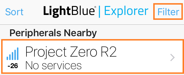
Connect to the device by clicking on the name. You can press the filter button in the top right corner to filter out all devices out of reach by setting a RSSI threshold (for example -50 dBm).
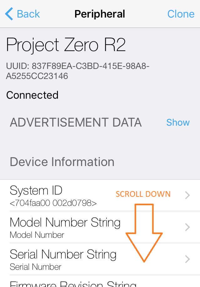
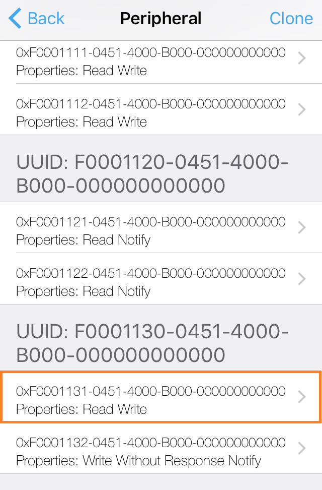
3. Find Data Service (UUID 1130) Scroll down until you find the data service and open the string characteristic which is marked with an orange box below.
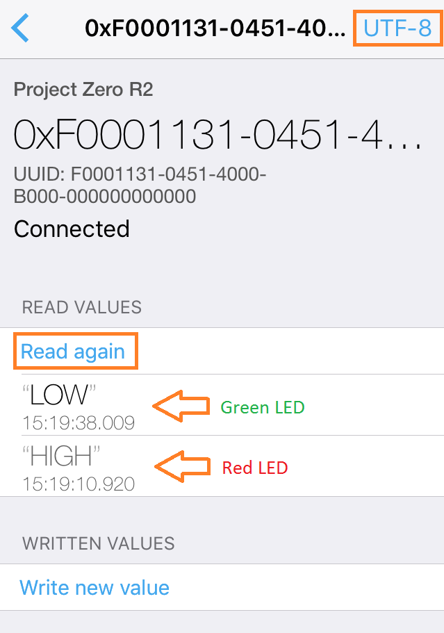
4. Read String Characteristic In the top right corner, change the format to UTF-8 and then press the "Read again" button to read the current characteristic value. This value will mirror the state.high variable in the sensor controller driver taht indicate either HIGH or LOW input value onn the ADC input pin. Move the header to change the ADC input between high and low input and press the "Read again" button to retrieve the new state.
Bonus Tasks 2 – Integrate with Proprietary RF (CC13x0 or CC13x2)
In this training, we are again porting our simple application. However, now we
are connecting it with Proprietary RF instead of BLE. We are modifying an
already existing Proprietary Tx example project, called RF Packet TX. The
application will be the transmitter, reading and storing the dawn state in a
RF packet, while the second device will be the receiver, using SmartRF Studio
to listen for the packet.
Hardware requirement
This bonus task requires two CC13xx LaunchPads; one for Tx and one for Rx.
Import and modify RF Packet TX
First, import a fresh version of the project RF Packet TX from the Resource
Explorer in CCS. It can be found in the SimpleLink CC13x0 SDK or
[SimpleLink CC13x2 SDK][CC13x2 SDK] package. Expand box below for reference.
In CCS, do the following:
Copy and paste all 6
scifrelated code files fromEmpty (Minimal) Projectinto the project base folder inRF Packet TX.Open up
rfPacketTx.cin CCS.Copy and paste the following code snippet at the top of the file.
#include <string.h>   // strlen() and memcpy()
#include <ti/sysbios/knl/Semaphore.h>
#include "scif.h"

#define BV(x)    (1 << (x))

Semaphore_Struct semMainLoop;
Semaphore_Handle hSemMainLoop;
Header Includes and Variable Declarations
Go to the already existing
pinTable[]array and change the first PIN instance fromBoard_LED1toBoard_LED0. Remember thatLED1is controlled by the SC.Copy and paste the SC callbacks.
void scCtrlReadyCallback(void)
{
    // Do nothing
} // scCtrlReadyCallback

void scTaskAlertCallback(void)
{
    // Signal main loop
    Semaphore_post(hSemMainLoop);
} // scTaskAlertCallback
SC Callbacks
- In
TxTask_init(), add initialization for the semaphore
// Main loop Semaphore initialization
Semaphore_Params semParams;
Semaphore_Params_init(&semParams);
semParams.mode = Semaphore_Mode_BINARY;
Semaphore_construct(&semMainLoop, 0, &semParams);
hSemMainLoop = Semaphore_handle(&semMainLoop);
Semaphore Initialization
In
txTaskFunction(), copy and paste the SC Driver initialization at the top of the function.At the bottom of
txTaskFunction(), replace the whole main loop with the code below
// Main loop
while(1) {
  // Wait for signal
  Semaphore_pend(hSemMainLoop, BIOS_WAIT_FOREVER);

  // Clear the ALERT interrupt source
  scifClearAlertIntSource();

  // Get 'state.high', and set highStr to appropriate string
  uint16_t high = scifTaskData.adcLevelTrigger.state.high;
  const char *highStr = (high != 0) ? "HIGH" : "LOW";
  uint16_t highStrLen = strlen(highStr);

  // Populate packet, and set pktlen
  packet[0] = (uint8_t)(seqNumber >> 8);
  packet[1] = (uint8_t)(seqNumber++);
  memcpy(packet + 2, highStr, highStrLen);
  RF_cmdPropTx.pktLen = 2 + highStrLen;

  // Send packet Tx
  RF_runCmd(rfHandle, (RF_Op*)&RF_cmdPropTx, RF_PriorityNormal, NULL, 0);

  // Toggle pin
  PIN_setOutputValue(ledPinHandle, Board_LED0, high);

  // Acknowledge the ALERT event
  scifAckAlertEvents();
}
Application Main Loop
- Build and debug project.
Test Proprietary RF application
To test the application, do the following:
- While the transmitter is running on one of the devices, open up SmartRF Studio. If both devices show up on the list of connected devices, disconnect the transmitter while setting up the receiver.
- Double click the available device, and choose
Proprietary Mode. - Choose the
50 kbps, 2-GFSK, 25 KHz deviationsetting at the top. This is usually the default. - Go to the
Packet RXtab. - In the tab, check of
infinitepacket count, set viewing format toText, and clickStart. - Try moving the wire or jumper on the transmitter. Packets with the dawn state should show up in SmartRF Studio.
You should see something like the picture below. Note the red markings.
