Meet the SimpleLink LPSTK-CC1352R LaunchPad SensorTag Development Kit
Your LaunchPad's features
- Featured MCU: CC1352R
- Connectivity: Sub-1 GHz + 2.4 GHz bands
- CPU Speed: 48MHz
- Non-volatile Memory (KB): 352kB
- RAM (KB): 80kB
- Learn more about the CC1352 MCU on ti.com
- LPSTK-CC1352R Tool Folder
Kit Overview
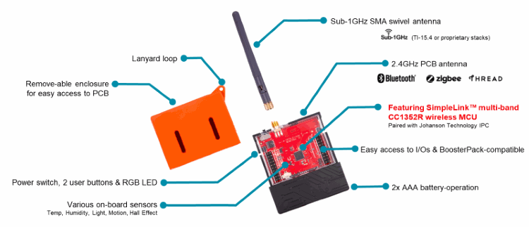
- Fully enclosed with cutouts for on-board sensors
- On-board environmental sensors
- Battery powered (AAA or CR2032)
- Integrated PCB antenna for 2.4 GHz, external antenna for sub-1Ghz
- 10-pin ARM JTAG connector for debugging
- 40-pin BoosterPack™ connectors to expand the LaunchPad SensorTag with BoosterPacks
- CC1352R wireless microcontroller device
- User LEDs (Red, Green and Blue)
- 2x User buttons
- 8 Mbit serial (SPI) flash memory
Learn more about how to use the CC1352R LaunchPad SensorTag in the Your LaunchPad Pinout section below!
On-Board Sensors
The LaunchPad SensorTag features several on-board sensors to help jump start your development. Additional sensors can be added using the LaunchPad connectors with BoosterPacks
- HDC2080 Temperature and Humidity
- Ultra-low-power, digital humidity sensor with temperature sensor
- I2C address: 0x40
- OPT3001 Ambient Light
- Digital ambient light sensor (ALS) with high-precision human-eye response
- I2C address: 0x40
- DRV5032 Hall effect
- Ultra-low-power digital-switch Hall effect sensor
- Digital input to the MCU
- ADXL362 Accelermoeter
- Digital Output MEMS Accelerometer
- SPI-based communication
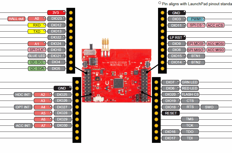
Your LaunchPad Pinout
All LaunchPad kits adhere to the BoosterPack pinout standard (documented here). You can see the documentation for this specific LaunchPad here within TI Resource Explorer.
You can find them by navigating here within TI Resource Explorer:
Development Tools→Kits and Boards→CC1352R LaunchPad→[Docs]
Device Overview
The CC13X2 family of wireless MCUs contain a 32-bit ARM® Cortex®-M4F processor running at 48 MHz as the main application processor, 352 kB of in-system programmable flash memory, 80 kB of low-leakage SRAM, a full complement of peripherals such as I2C, SPI and UART, advanced cryptography accelerators (ECC, AES256, SHA256, etc.) as well as a Sensor Controller Engine (SCE). The SCE is a 2nd programmable processor core ideal for ultra low-power sensor reading and data processing applications. The SCE runs independently from the main Cortex-M4F and handles sensor polling using just a few micro amps of average current. A dedicated Radio Controller (ARM Cortex-M0) handles low-level RF and physical layer (PHY) protocol commands that are stored in ROM or RAM, thus ensuring ultra-low power and great flexibility. A comprehensive list of capabilities can be found in the device data sheet and Technical Reference Manual.
CC1352R
The LAUNCHXL-CC1352R1 LaunchPad is a dual-band low power radio kit utilizing the CC1352R which enables Sub-1 GHz + 2.4 GHz in a single chip solution. The CC1352R LaunchPad enables development of wireless applications for the SimpleLink CC1352R wireless MCU supporting proprietary Sub-1 GHz, TI 15.4-Stack for IEEE 802.15.4e/g star based networking (868 MHz, 915 MHz and 2.4 GHz) and Bluetooth low energy (BLE) supporting Bluetooth 5 LE. With multiprotocol support, the CC1352R can run Sub-1 GHz and 2.4 GHz protocols concurrently, including, TI 15.4-Stack, Proprietary Sub-1 GHz, and BLE5.
Your LaunchPad's Out of Box Experience demo
Note for developers using a LAUNCHXL-CC1352R!
The LPSTK-CC1352R is used for the entirety of this lab, however, the same steps can be followed when using the CC1352R LaunchPad with BOOSTXL-BASSENSORS and BOOSTXL-ULPSENSE BoosterPacks.
The LPSTK-CC1352R is pre-programmed with a Bluetooth 5 (BLE5) example peripheral project called Multi-Sensor that allows wireless communication with smartphones and tablets over a BLE connection. The Multi Sensor example pairs up with the SimpleLink Starter smartphone application and demos how to interactively perform various actions such as reading sensor data, toggling LED's, reading button status, and updating the firmware using Over-The-Air Download (OAD) capabilities.
The Multi Sensor example source code is available in the SimpleLink CC13x2 26x2 SDK located at <simplelink_cc13x2_26x2_sdk install location>\examples\rtos\CC1352R1_LAUNCHXL\ble5stack\multi_sensor
Task 1. Flashing the Out of Box Project
Note for new LaunchPad SensorTags!
The LPSTK-CC1352R is pre-programmed with a Bluetooth 5 (BLE5-Stack) example peripheral project called Multi Sensor that allows wireless communication with smartphones and tablets over a BLE connection. This project serves as the Out of Box Experience for the LaunchPad SensorTag. If the device has never been used and just came out of the box, the user can skip to the next task.
If you've been using your LaunchPad for another project and want to restore the Out of Box functionality, you can revert your LaunchPad Sensor tag back to the factory image by holding BTN-1 while toggling the power switch off and then on. This will cause the LPSTK-CC1352R to revert to the factory image, which is store on the external SPI Flash.
Task 2. Out of Box Demo
Before starting, download the SimpleLink Starter smartphone application.
After downloading the SimpleLink Starter application to your smartphone, turn the LaunchPad SensorTag on using the power switch. The LaunchPad SensorTag will blink a Blue LED
Open the SimpleLink Starter smartphone app. It will automatically scan for nearby devices. You can refresh the list by pulling down.
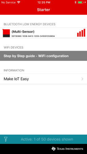
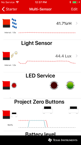
Your LaunchPad SensorTag will be advertising as "Multi Sensor". Connect to the device by clicking on the name and select Sensor View to get to the GUI.
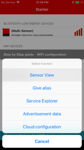
You will now be able to see sensor values and buttons status displayed in the app and toggle the user LEDs on the LaunchPad by clicking on them.
Task 3. Change stack with Over-the-Air Download (OAD)
With the out of box software pre-programmed on LPSTK-CC1352R you can change the stack with over-the-air download. There are three binaries pre-built to work with the LaunchPad SensorTag
- BLE Multi-Sensor
- TI 15.4 Sensor
- Zigbee Light Switch
To perform an OAD:
- When your smartphone is connected to a LaunchPad SenorTag running Multi Sensor (The Out-of-Box Software), go into Sensor View, scroll down and select FW Download.
- On the Enhanced OAD screen tap on Select FW File and select one of the supported images for the LaunchPad SensorTag (LPSTK)
- Select Program and then Start OAD to start the firmware update.
Note: You can also email binary images that have been compliled on your computer to yourself to open in the mobile app. This allows OAD of custom software.
Task 4. Restore to the factory image
After downloading a new image to the device, you can restore to the factory image by pressing BTN-1 (left button) during a boot/reboot using the following steps:
- Press and hold BTN-1
- While holding BTN-1, toggle power to your LaunchPad SensorTag off, then on again
- Release BTN-1
- The LaunchPad will now boot from its factory image and can be used in the same manner in Task 2.
Good to know
This section contains some tips and other good things to know about your LaunchPad SensorTag kit
Software Examples for LPSTK
There are three software examples specifically designed for the LaunchPad SensorTag Kit. However, any examples for LAUNCHXL-CC1352R in the SimpleLink CC13x2 26x2 SDK will also work with this kit.
The three software examples specifically for your kit are:
- BLE Multi Sensor
- This example is pre-programmed to your LPSTK out of the box
- Uses BLE to stream sensor data to a mobile app
- SDK Location:
\CC1352R1_LAUNCHXL\ble5stack\multi_sensor
- TI 15.4 DMM Sensor
- Uses TI-15.4 and BLE with DMM to create a long-range, low-power sensor node that can also be configured via BLE
- SDK Location:
\CC1352R1_LAUNCHXL\dmm\dmm_154sensor_remote_display_oad_lpstk_app - SimpleLink Academy
- Zigbee DMM Lightswitch
- Uses Zigbee to turn the LPSTK into a Zigbee lightswitch with the ability to use DMM and BLE to control the lighswitch from a mobile device
- SDK Location:
\CC1352R1_LAUNCHXL\dmm\dmm_zed_switch_remote_display_oad_app - SimpleLink Academy
For more information about these examples, click the SimpleLink Academy links above.
LPSTK Battery Operation and Disassembly
By default, the LPSTK-CC1352R operates using 2x AAA batteries inserted into the bottom compartments, as shown below. Due to regulatory restrictions, the LPSTK-CC1352R does not ship with AAA batteries included.
Alternatively, the LPSTK-CC1352 can be powered by a CR2032 coin cell battery (3V). To use the LPSTK-CC1352R with a CR2032 battery you will need to solder a coincell battery holder (Part umber: BAT-HLD-001) to the reverse side of the PCB. Please see the video below for more information on how to disassemble the LPSTK-CC1352R and install the CR2032 coin cell battery
Debugging the LaunchPad SensorTag
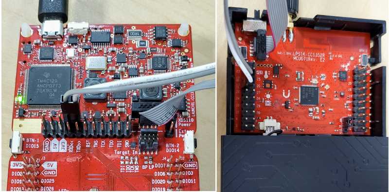
The LaunchPad SensorTag is designed to be used in conjunction with a LaunchPad development kit for debugging. Included in the box for the LaunchPad SensorTag is an ARM 10-pin JTAG cable and a 2 wire per for UART. Connecting these to an XDS110 LaunchPad (such as the LAUNCHXL-CC1352R) allows for full debugging, programming, and UART communication.
- Disconnect the debug isolation jumpers on your LaunchPad
- Connect the ARM 10-pin JTAG cable to
XDS110 OUTheader on your LaunchPad - Connect the other end of the ARM10-pin cable to the
JTAGheader on your LaunchPad SensorTag - Connect the 2-pin jumper cable to the top pins of RXD and TXD (grey wire to RXD, white wire to TXD)
- Connect the other end of the 2-pin jumper to pins 12/RX and 13/TX on the LaunchPad SensorTag (Grey to 12/RX, white to 13/TX)
- Connect your XDS110 LaunchPad to your PC!
Important Note about Debugging custom software
If you are debugging custom software on the LPSTK, please refer to the next section to learn the CC1352R Boot Image Manager (BIM)
Here's what your setup should like for debugging!
Boot Image Manager (BIM)
A running image cannot update itself. This means that incoming OAD image must be stored in a temporary location while it is being received. This temporarily location can be a reserved location in internal flash (onchip) outside of the executable area covered in the first image. Alternatively, the temporary location can be in an external flash chip (offchip)
After the download is complete, the device must determine if the new image is valid, and if current image should be overwritten, and finally execute the new image.
To do this, the device runs a piece of code called the Boot Image Manger (BIM) in the TI OAD solution.
BIM is intended to be permanently resident on the device, meaning it persists through many OADs and cannot be updated.
BIM will run every time the device boots and determine if a new image should be loaded and run (based on image header).
The Out of Box software on the LPSTK-CC1352R uses the Boot Image Manager (BIM) to allow the user to revert to the Out of Box image after an Over-the-Air Download (OAD).
If you hold BTN-1 (left button) on power-up or during a reset, the BIM will revert to the Out of Box image (Multi Sensor) which is stored in external flash (offchip). If you OAD a new image to the LPSTK that is not OAD enabled, you may not be able to revert back to the Out of Box image. If you want to enable this functionality in your custom application, refer to the Multi Sensor example source code.
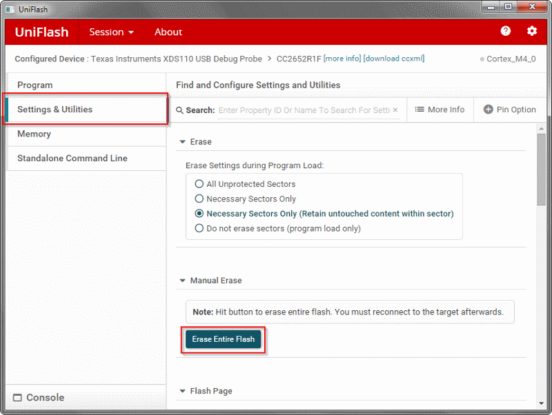
If you want to run custom software on the LaunchPad SensorTag that does not take advantage of BIM, it is reccomended you use Uniflash to erase the entire flash. (Uniflash > Settings and Utilities > Manual Erase > Erase Entire Flash)
More information about the BIM can be found in the README for the multi_sensor project in the SDK, or in the BLE5-Stack User's Guide.
Debugging with BIM
If you are debugging your code using an IDE (as opposed to running your code after a reset), BIM will not run at all. If you reset during a debug session, the BIM (if present) will run and may overwrite your code with the factory image.
Your LaunchPad Resources
- LPSTK-CC1352R
- SimpleLink CC13X2 / CC26X2 SDK Documentation Overview
- CC1352R Datasheet
- CC1352R Technical Reference Manual
- SimpleLink Academy for LPSTK
Meet the LaunchPad SensorTag Kit Technical Article
For additional CC1352R technical documents, please see the product page: https://www.ti.com/product/CC1352R/technicaldocuments
Start Developing on your LaunchPad
Your LaunchPad can be programmed using the official SimpleLink SDK that corresponds with the device you are working with.
Get started with the SimpleLink CC13X2 / CC26X2 SDK
Get started with the SimpleLink CC13X2 / CC26X2 SDK - a complete software development kit for your device. Within the SDK, you will find code examples, drivers, middleware, documentation, migration guides & more.
Checkout SimpleLink Academy
- SimpleLink Academy is a comprehensive collection of trainings & exercises to get you up and running with the SimpleLink SDK.
- Visit the SimpleLink Academy Overview page to see recommended content for this LaunchPad.
Checkout the SimpleLink CC13X2 / CC26X2 SDK Documentation Overview
Compliance Information
CE Compliance
Texas Instruments declares that this product is in compliance with Directive 2014/53/EU. The compliance has been verified in the operating bands of 868 MHz to 868.6 MHz at +14 dBm Tx Power setting and 2402 MHz to 2480 MHz at +5 dBm Tx Power setting. Should you choose to configure the EUT to operate outside of the test conditions, it should be operated inside a protected and controlled environment (such as, a shielded chamber). This evaluation board is only for development and not an end product. Developers and integrators that incorporate the chipset in any end products are responsible for obtaining applicable regulatory approvals for such end product.
For CE Mode
2.4GHz Band (BLE):
- Use Typical Setting – Bluetooth5, LE 1M PHY (1 MSym/Sec GFSK, 1MBPS data rate) from SmartRF Studio or Out-of-box Code
- Use the Tx Power Setting of +5dBm or Lower from SmartRF Studio
- Use the Integrated PCB Antenna only
868MHz Band:
- Use Typical Setting - Data Rate / Modulation: 50KBPS, 2-GFSK, 25KHz Deviation from SmartRF Studio
- Use the Tx Power Setting of +14dBm or Lower from SmartRF Studio
- Use the supplied Whip Antenna only
For FCC/IC Mode:
2.4GHz Band ( BLE):
- Use Typical Setting – Bluetooth5, LE 1M PHY (1 MSym/Sec GFSK, 1MBPS data rate) from SmartRF Studio or Out-of-box Code
- Use the Tx Power Setting of +5dBm or Lower from SmartRF Studio
- Use the Integrated PCB Antenna only
915MHz Band:
- Use TI 15.4 - Stack: Mode: Frequency hopping , PHY ID = 1 and PHY Data Rate = 50KBPS
- Use the Tx Power Setting of +11dBm or Lower
- Use the supplied Whip Antenna only
REACH Compliance
In compliance with the Article 33 provision of the EU REACH regulation we are notifying you that this module includes a Crystal 32.768KHz, Mfg PNo: FC-135 32.7680KA-AG0 from Epson that contains a Substance of Very High Concern (SVHC) above 0.1%. These uses from Texas Instruments do not exceed 1 ton per year. The SVHC is Lead titanium trioxide CAS# 12060-00-3.
A.3.2 CAN ICES-3(B) and NMB-3(B) Certification and Statement
This device complies with Industry Canada license-exempt RSS standards.
Operation is subject to the following two conditions:
- This device may not cause interference.
- This device must accept any interference, including interference that may cause undesired operation of the device.
Le présent appareil est conforme aux CNR d'Industrie Canada applicables aux appareils radio exempts de licence.
L'exploitation est autorisée aux deus conditions suivantes:
- L'appareil ne doit pas produire de brouillage.
- L'utilisateur de l'appareil doit accepter tout brouillage radioélectrique subi, même si le brouillage ests susceptible d'en compromettre lu fonctionnement.
CAUTION
IC RF Radiation Exposure Statement:
This equipment complies with IC radiation exposure limits set forth for an uncontrolled environment. This equipment should be installed and operated with a minimum distance of 20 cm between the radiator and your body.
Déclaration d'exposition aux radiations:
Cut équipement est conforme aux limites d'exposition aux rayonnements IC établies pour un environnement non contrôlé. Cet équipement doit être installé et utilisé avec un minimum de 20 cm de distance entre la source de rayonnement et votre corps.
This work is licensed under a Creative Commons Attribution-NonCommercial-NoDerivatives 4.0 International License.