Frequency-Hopping Low Latency Broadcast Mode
Introduction
The TI 15.4-Stack can be configured to operate the network in frequency-hopping low latency broadcast configuration. The configuration is done in SysConfig -> RF Stacks -> TI 15.4-Stack -> Mode.
This configuration leverages the broadcast functionality of the frequency-hopping stack to implement a low latency protocol similar to the communication pattern of the beacon mode.
The collector (PAN coordinator) hops on different frequencies and the sensors (sleepy nodes) follow this hopping sequence. The frequency hopping is based on the directed frame exchange (DFE) mode of the Wi-SUN FAN specification 1.0.
The collector transmits periodic broadcast messages to allow the sensors to perform synchronization and send data/commands to them. This allows the sensors to stay synchronized and to receive data by only performing RX operations leading to super low power consumption.
To enable sleepy devices in TI 15.4-Stack frequency-hopping networks a proprietary sleep mode extension is implemented following the behavior defined in the Wi-SUN FAN and IEEE 802.15.4 MAC protocols (see Sleep Mode Operation).
Additionally, the join and re-join is speed up by the collector sending regular asynchronous PAN configuration frames which allows the sensors to re-join in seconds after timeout detection.
Attention
The frequency hopping low latency broadcast configuration is only supported on Sub-1 GHz frequency bands.
Network Operations
A frequency-hopping low latency broadcast network consists of the following two types of devices:
Non-Sleepy PAN Coordinator - Collector
Sleepy Nodes - Sensors
A typical star topology has a single collector connected to a set of sleepy sensors. Each network is identified by a specific network name, which is an ASCII value of 32 bytes and a 16-bit PAN Identifier. The network name (NetName) is a unique network identifier that is configured by the application using frequency hopping and PAN information base (FH-PIB) attributes. Maintenance of the NetName is beyond the scope of TI 15.4-Stack and is not used to filter frames.
This section explains various network operations important to understand when developing an application using the frequency hopping low latency broadcast configuration.
Device & Network Start-Up
The network is started by the collector (PAN Coordinator) in frequency-hopping low latency broadcast configuration following the startup sequence in Figure 72..
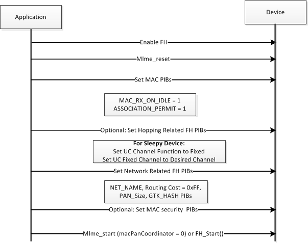
Figure 78. Start-Up Sequence of PAN Coordinator and the nodes
The PIB attributes that are related to frequency-hopping configuration are explained in Application Configuration. The NetName is a 32-bit ASCII value to be set by the application. The routing cost must be set to zero.
Initially, the PAN size must be set to zero; later, the PAN size must be updated based upon the number of nodes joined.
Note
This NetName value is not used by the TI 15.4-Stack to make any decision; instead, the value is carried in a PAN Advertisement frame that can be parsed by a receiving application. Similarly, the GTK HASH 0, GTK HASH 1, GTK HASH2, and GTK HASH 3 can be used to determine the validity of GMK keys that are in use and are beyond the scope of TI 15.4-Stack.
Up to here the start-up sequence is the same for the sleepy sensors. Next, the collector starts the MAC using the macStart API, which specifies that it is a PAN coordinator.
The collector starts a broadcast and a unicast hopping sequence based on it’s fixed channel function as shown below Figure 79..
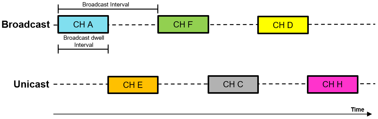
Figure 79. Collector hopping sequences
Network Join
To join to a network, a sensor must go through the two phases described as follows.
Phase 1: Exchange of Channel-Hopping Sequence Information Through Asynchronous Messages
Asynchronous messages are sent back-to-back over a specified channel list. This action enables a receiver to receive such frames with high probability, irrespective of the hopping sequence. Three different asynchronous messages are used by TI 15.4-Stack in low latency broadcast configuration. They are implemented as defined in the Wi-SUN FAN specification. The PAS and PA asynchronous frames are transmitted based on a trickle timer [RFC 6206]. The Imin, Imax, and K for the trickle algorithm are recommended to be set at 1 min, 16 min, and 1, respectively. The PC asynchronous frames are transmitted regularly by the collector every 3.5 s which accounts for the maximum channel TX activity defined by FCC.
Brief descriptions of the 3 types of asynchronous messages:
PAN Advertisement Solicit (PAS):
PAS messages are used by a device to request a coordinator or other joined nodes to transmit a PAN Advertisement frame.
Upon reception of the PAN Advertisement frame, a joining application can detect the NetName IE in the frame and then use the name to determine whether or not to reset PA trickle timer.
PAN Advertisement (PA):
PA frames can be transmitted by a coordinator to inform neighbors about the PAN size, Routing cost, and PAN ID.
The trickle timer associated with PA transmissions is programmed to be reset on reception of a PAS frame.
Upon, reception of the PAS frame, nodes communicate with the transmitter of the PA frames (note the hopping sequence is carried in the PA frame).
PAN Configuration (PC):
PC messages are transmitted by the coordinator at a fixed interval on a dedicated async channel that is not part of the unicast and broadcast fh channel map. It is used to speed up the join process and to allow for a quick re-join
PC frames carry the broadcast-hopping sequence and the hash values of the list of GMK keys that are actively used.
Upon reception of a PC frame, a device detects that the channel-hopping exchanges are completed.
Phase 2: Proprietary Association Procedure to Inform Coordinator of the Network Join (This is an Optional Step)
Because the frequency hopping join procedure (defined by the Wi-SUN specification) is silent, the PAN coordinator cannot detect if the device has successfully joined the network. The TI 15.4-Stack example applications use an additional step for network join. The MAC layer association procedure described in the IEEE 802.15.4 specification is used after the PCS indicates to the PAN coordinator that the device has successfully joined the frequency-hopping network.
In addition to informing the coordinator that the device has successfully joined the network, the optional mechanism allows the PAN coordinator to detect if the joining node is sleepy or always-on through the capability information field of the association request message sent by the device to the PAN coordinator. This optional mechanism is required for the PAN coordinator application to determine the following:
If the application must buffer the message until the device polls for some configured amount of time in case the message is for a sleepy device
If the application must send the message OTA as soon as the message- transmit request is generated
Note
The association procedure must be started at least 2 seconds after
reception of a PAN configuration frame. Upon failure, the association
procedure can be independently retried up to the retry limit of the
application. For a sleepy device, the ApiMac_attribute_RxOnWhenIdle
should be set to zero only after a successful completion of the mac-
association procedure.
Figure 73. shows the join procedure for a sensor (sleepy node).
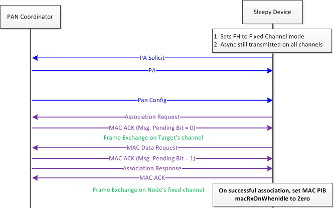
Figure 80. Joining Procedure for a Sleepy Frequency-Hopping Device
Wi-SUN FAN v1.0 does not specify sleep mode operation, but the TI 15.4-Stack implements a proprietary extension over the behavior defined in the Wi-SUN FAN and IEEE 802.15.4 MAC protocols to enable sleepy devices in the frequency-hopping networks based on TI 15.4-Stack. The channel-hopping function for a sleepy device must be set to Fixed, and the fixed channel can be set to any desired channel. The security keys can be set at start-up (if the security keys are already pre-configured for the network), or the security keys can be set after obtaining the same through a key exchange. The key exchange protocol must be handled above the MAC layer.
A sleepy device is configured to be sleepy by setting the MAC PIB (macRxOnWhenIdle) to zero only after it joins the network.
The routing cost must be set to a high value (0xFFFF) to indicate that the device has not joined the network; later, it can be updated by the application based on the routing metric used.
Data Exchange
The data exchange in the TI 15.4-Stack Frequency-Hopping Low Latency broadcast is based on a broadcast data exchange and unicast data exchange. The communication from Collector to Sensor uses only broadcast data exchange (heartbeat broadcast). The broadcast message consists of the broadcast header and payload. The payload can be customized. By default the payload consists of a field for the destination device address and a command. To achieve low latency the collector sends a broadcast message in every broadcast interval (default 1 s).
The sensor wakes up according to the broadcast interval for the broadcast dwell time (default 20 ms). For every broadcast message that is received by the sensor it synchronizes with the collector and resets it’s disconnection detection timer (see Timeout detection & Re-Join).
After receiving a broadcast message the sensor compares the address carried in the broadcast payload to its device address. If the address matches it processes the command from the broadcast payload and sends an acknowledgement to the collector.
The Acknowledgement is sent as unicast message. The collector stays in RX on the current unicast channel between the broadcast intervals, and is thus ready to receive the acknowledgement.
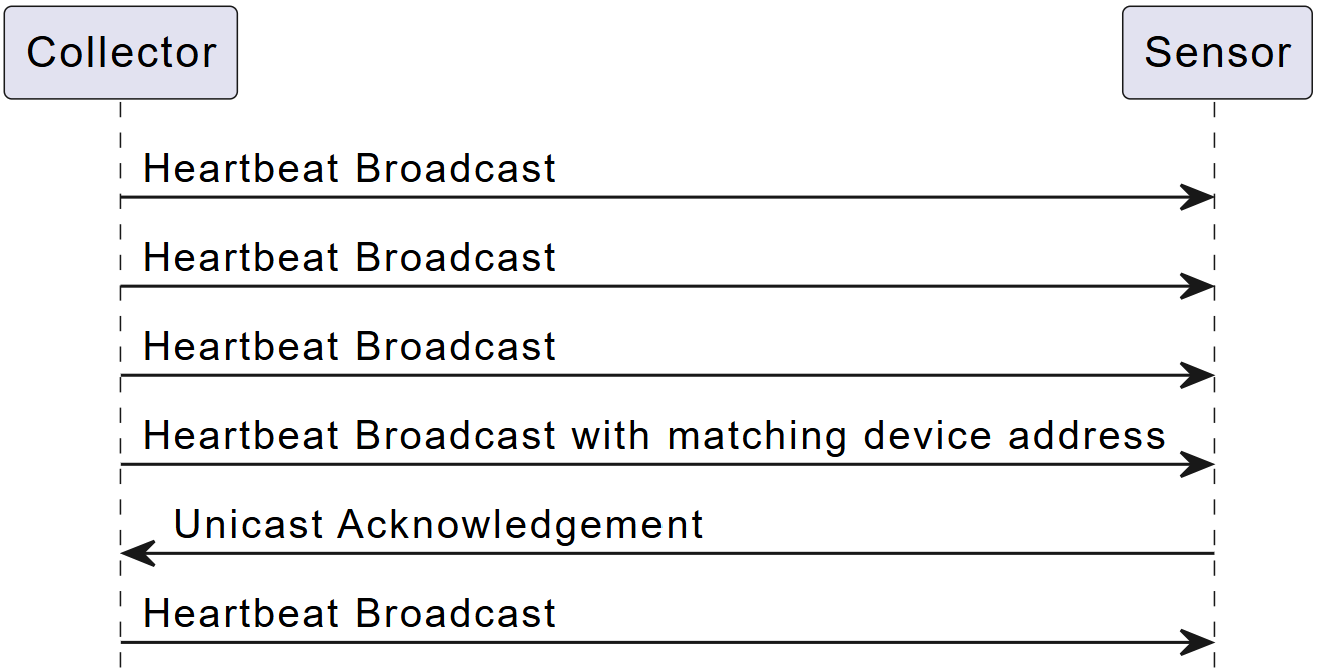
Figure 81. Data Exchange with TI 15.4-Stack in Frequency-Hopping Low Latency Broadcast Configuration
Note
The broadcast interval FH_BROADCAST_INTERVAL is configured in SysConfig.
Timeout detection & Re-Join
In the frequency hopping low latency broadcast configuration the sensor devices are responsible for tracking their connection to the collector. As explained in the previous section Data Exchange, the sensors reset with every received broadcast message their disconnection detection timers (default 5 s).
If the disconnection detection timer runs out before the sensor receives the next broadcast message from the collector, it will trigger a re-join.
For the re-join the sensor switches in continuous RX to the dedicated channel on which the collector sends regularly the Pan Configuration Frame (PC). After the sensor receives the first of these PC frames it will immediately re-join the network and receive again broadcast messages.
This allows for a re-join in seconds.
Note
By adjusting the disconnection detection timeout interval you can configure to allow a custom number of missed heartbeat broadcasts.
It is recommended that the disconnection detection timeout interval is at least double the broadcast interval. In this case the re-join is triggered after one broadcast message is missed.
For robustness the timeout should be chosen lager to allow for missing multiple broadcast messages. This makes the network resilient against single channel jamming.
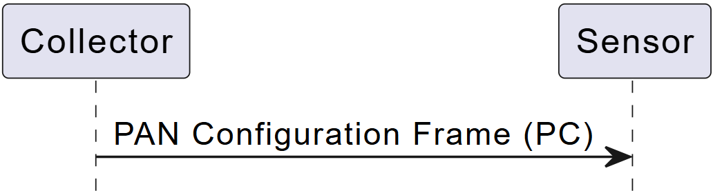
Figure 82. Re-Join with TI 15.4-Stack in Frequency-Hopping Low Latency Broadcast Configuration
Application Configuration
The frequency-hopping low latency broadcast mode can be controlled through a set of settings exposed in SysConfig and the sensor and collector application. The most relevant are listed below.
Parameter |
Default |
Description |
|---|---|---|
CONFIG_FH_CHANNEL_MASK |
All channels available in the region except the last. |
Broadcast and unicast channel map. |
FH_ASYNC_CHANNEL_MASK |
The last channel of the regional available channel map. |
Asynchronous channel mask. |
CONFIG_SECURE |
MAC security |
Network security level. |
Parameter |
Default |
Description |
|---|---|---|
FH_BROADCAST_INTERVAL |
2000 |
Broadcast interval (halved by the stack) in ms. |
FH_BROADCAST_DWELL_TIME |
20 |
Defines the length of the sensors broadcast slot in ms. |
Define |
Default |
File |
Description |
|---|---|---|---|
LOW_LATENCY_BROADCAST_MAX_RETRIES |
3 |
collector.c |
Maximum number of retries for each broadcast appended command. |
LOW_LATENCY_BROADCAST_PC_INTERVAL |
3500 |
cllc.c |
Interval in which the collector sends pan configuration frames on the aync channel in ms. |
LOW_LATENCY_BROADCAST_CONFIGURATION_TIMEOUT |
5000 |
sensor.c |
Sensor disconnection detection timer in ms. Reset with every received broadcast. |
LOW_LATENCY_BROADCAST_START_TIMEOUT_DETECTION |
120000 |
jdllc.c |
Timer to start the disconnection detection delayed to allow for the configuration update in ms. |
Broadcast Header |
1 byte: Command ID |
2 bytes: Destination Device Address |
1 byte: Command |
Unicast Header |
1 byte: Command ID |