Flash Vector Table
This table contains the reset value of the stack pointer, and the start addresses, also called exception vectors, for all exception handlers. The first 15 exception vectors are necessary system exceptions, followed by a variable number of Interrupt Request (IRQ) vectors. The location of this table is fixed to address 0x00000000. At bootup time, the RTOS kernel will run a first function to initialize the Hwi module.
For more information about the vector table format, please refer to Cortex-M0 Vector Table.
For more information on the kernel boot process and first functions, please see FreeRTOS (RTOS Kernel) Overview.
Customer Configuration (CCFG) Table
The CCFG is placed at the end of the last flash page and lets the customer configure various chip and system parameters in the Customer Configuration (CCFG) table. Parameters can be determined in the SysConfig (*.syscfg) file through the TI Devices → Device Configuration options. The last (sizeof(ccfg_t)) bytes of the CCFG sector are reserved by the system for the CCFG table. By default, the linker allocates the unused flash of the last flash page to the application image for code and data use.
See the CC23xx SimpleLink Wireless MCU Technical Reference Manual for details on CCFG fields and related configuration options, including how to set the CCFG to disable access to internal flash memory contents.
Note
The CCFG cannot be relocated, and must reside at the end of the last page of flash. Consult the CC23xx SimpleLink Wireless MCU Technical Reference Manual for more information.
Note
If SET_CCFG_ERASE_CONF_CHIP_ERASE_DIS_N is set to 0 it’s not possible to do mass erase.
User Record
The user record is a 128-byte record in CCFG that can be written at the same time as CCFG is written or with a separate command later. This allows the user record to be written as part of a commissioning step separate from the application image that has been programmed. Consult the CC23xx SimpleLink Wireless MCU Technical Reference Manual for more information.
In this case the user record typically contains some kind of device unique ID, address or key. For instance, it can be used to:
Store a custom
Public Addressinside the CCFG memory section which will not get erased by OAD procedures.Store custom keys inside the CCFG memory.
Write into the User Record for Debugging or Developing purposes
It is possible to leverage the SysConfig interface for this purpose by following the next steps:
Create a
.hfile and define the values that you want to write into the User Record. For example:1#define CCFG_USER_RECORD .val8={0x01, 0x02, 0x03, 0x04, 0x05, 0x06}Open SysConfig and go to
Device Configurationinside theTI Devicessection.Search for
Hardware Initialization And User Dataand modify the following:
Click on
Enable User Record.Include the name of the defined variable inside the
User Record Macrofield. In the previous example:CCFG_USER_RECORD.Include the path where the
.hfile can be found.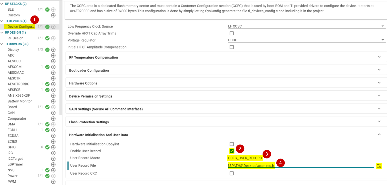
Figure 140. Setting the User Record using SysConfig.
Right click on the project and select
Properties.Go into the
Debugoption and disable the optionSkip Programming of CCFG user recordinside theFlash Settingssection.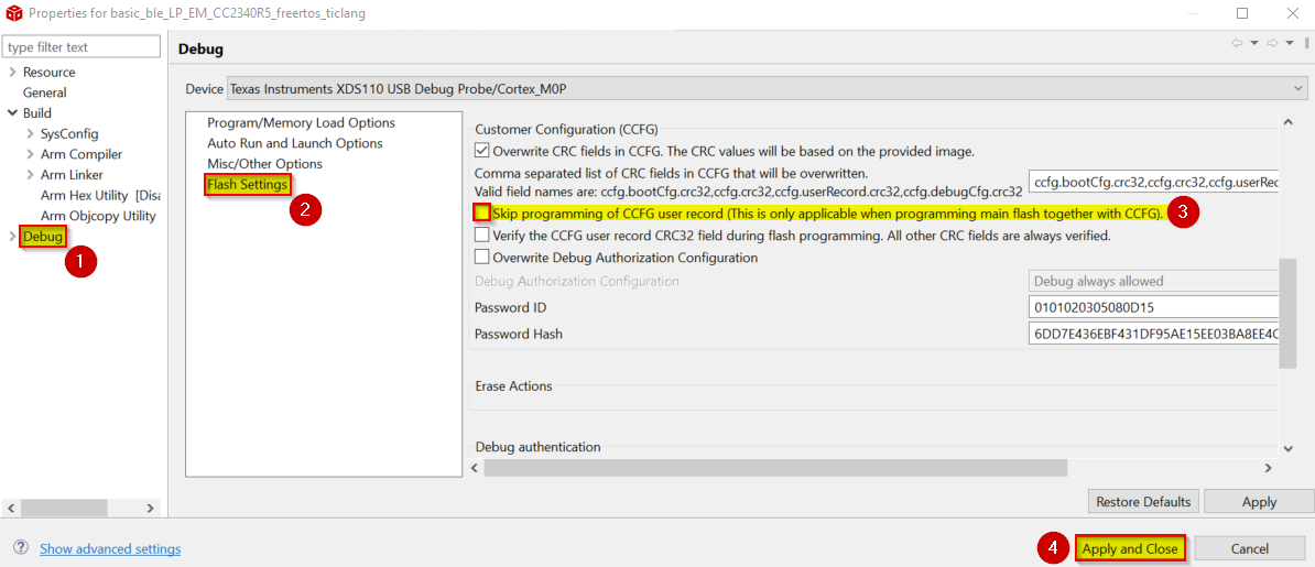
Figure 141. Disable option to Skip Programming of CCFG user record.
Build the project and flash it into the device.
Warning
This is only applicable when programming the main flash along with the CCFG.
To verify that the values have been properly flashed into the User Record section of the CCFG, you can use the
Memory Browserwhile running in Debug mode. The User Record section starts at the address:0x4e020750.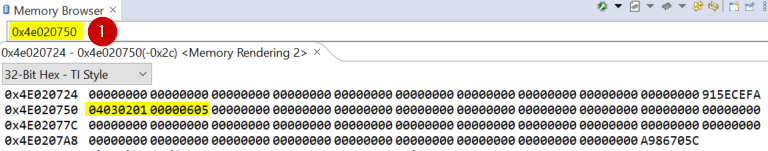
Figure 142. Verify User Record value inside CCFG.
Write into the User Record while in Production
Warning
UNIFLASH version 8.7 or higher must be used when flashing into the User Record to avoid unknown issues with the device.
Select the
.binfile with the values you want to flash into the User Record. You can also use the tool provided in Generate a User Record binary file with CRC, which generates a.binfile from a.txtfile. However please consider this tool also generates the CRC code at the last 4 bytes, reducing the available space that you can use inside the User Record to 124 bytes.Warning
All bytes in the CCFG user record must not have been previously modified (the values must be 0xFF) before attempting to program the CCFG user record. This can be avoided when programing into the main flash by using the
Skip Programming of CCFG user recordCCS option previously mentioned. If flashing the program from UNIFLASH, please find this option inside Settings & Utilities –> CCFG.
Open UNIFLASH and select the
.binfile along with the load address, which is the CCFG User Record address:0x4e020750.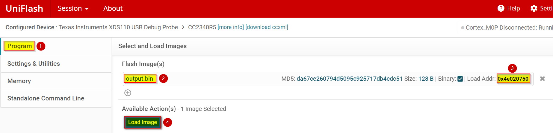
Figure 143. Select program to load into User Record with UNIFLASH.
Once the image has been successfully loaded, please power cycle the device and restart UNIFLASH again.
Go to
Memoryand click onRead Target Device. Search for the CCFG User Record address.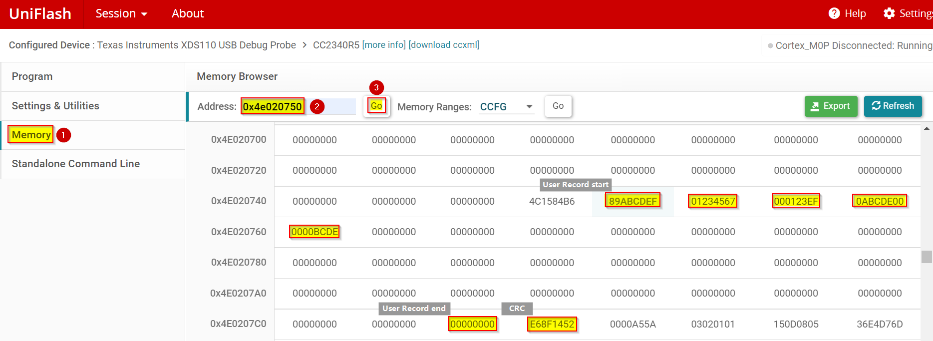
Figure 144. Verify that the User Record has been correctly modified.
Note
In case you need to generate a User Record binary file with CRC, refer to Generate a User Record binary file with CRC.
Read the User Record value from the application code
Please consider the following example as reference.
    #include <ti/devices/DeviceFamily.h>
    #include DeviceFamily_constructPath(inc/hw_ccfg.h)
    #include <string.h>

    extern const ccfg_t ccfg;

    unsigned char buffer[6];
    void *user_record_source = (void*)ccfg.userRecord.val8;

    //Copy the User Record values into the buffer.
    memcpy(buffer, user_record_source, sizeof(buffer));
Note
If you do not require the entire user record size, just define the amount of bytes to copy (reducing
USER_RECORD_SIZEin our previous example). For instance, if you flashed a Bluetooth LEPublic Address, then you will need to read only the first 6 bytes.
CRC Tool
Please find the tool inside the SDK directory: <SDK>\tools\common\crc_tool.
The CRC tool has two main features:
1. Adding CRC values to an ELF file: Parse an Executable and Linkable Format (ELF) file. Calculate CRC values over sections of memory as defined in the linker command file, and insert these CRC values after the end address, as defined by these symbols. This can be used as a post build step to add CRCs to the generated ELF file.
2. Generate a User Record binary file with CRC values: Parse a text file, containing one or more hexadecimal values, merge this data and pad up to 124 bytes, calculate the CRC of this value and generate a binary file containing 124 bytes of data and 4 bytes of CRC. This is intended to be given as input to a SACI Flash Programming command for programming the user record in the CCFG.
Note
The generated user record binary can be flashed in production line even with debug locked and without affecting the actual application.
Adding CRC values to an ELF file
For crc_tool to know where to insert CRC values it needs to be able to find symbols in the ELF file
which matches the stated prefix. All symbols without a matching prefix are ignored. Symbols need to
come in pairs with matching names, except for _end, and _begin suffixes. Symbols without a suffix,
or without a matching counterpart are ignored.
The following cases are examples of what the tool expects. These symbols must be introduced inside the linker command file
(.cmd, .icf, .lds) which can be found inside the project.
Listing 155. Example of symbol definition. The addresses shown here are for illustrative purposes only.¶__my_prefix_name1_begin = 0x4E020000; __my_prefix_name1_end = 0x4E02000B; __my_prefix_name2_begin = 0x4E020010; __my_prefix_name2_end = 0x4E02074B;
Warning
If you have the _end values of two sections within the same 4 byte range, meaning that
they would overwrite each other’s CRCs, then an error is thrown. In addition, the value of the
_end symbol must be greater or equal than the _begin value, otherwise an error is also thrown.
It is possible to use the addresses and Symbols generated by GenMap (See: GenMap). To see these symbols and their respective addresses please do the following:


The crc_tool tool will take an ELF file as input and output an ELF file with inserted CRC values. This can be automated
by using CCS post-build steps. To do this, please follow the next steps:
Add the symbols to the
.cmdfile of the project.Right-click on the project file and search for
Properties.Inside
Buildlook forEnvironmentand click onAdd... Add a new variable calledCCS_CRC_TOOL_DIRwith value equal to:C:\ti\simplelink_lowpower_f3_sdk_x_xx_xx_xx\tools\common\crc_tool, wheresimplelink_lowpower_f3_sdk_x_xx_xx_xxvalue must be updated to match the version of the used SDK.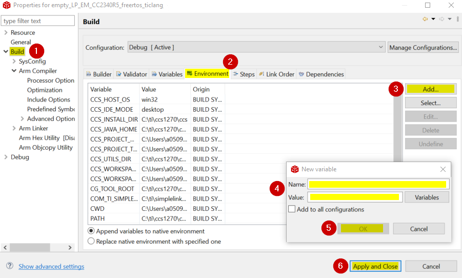
Figure 147. Adding environment variable for CRC Tool.
Inside
Buildlook forStepsand include the following line inside thePost-build steps. Please make sure that you are using the same prefix inside the ELF file as the one declared below (in our example:__my_prefix) with the--symbol-prefix.
${CCS_CRC_TOOL_DIR}\crc_tool.exe patch-image --elf ${BuildArtifactFilePath} --symbol-prefix __my_prefix_name1 --output ${BuildArtifactFilePath}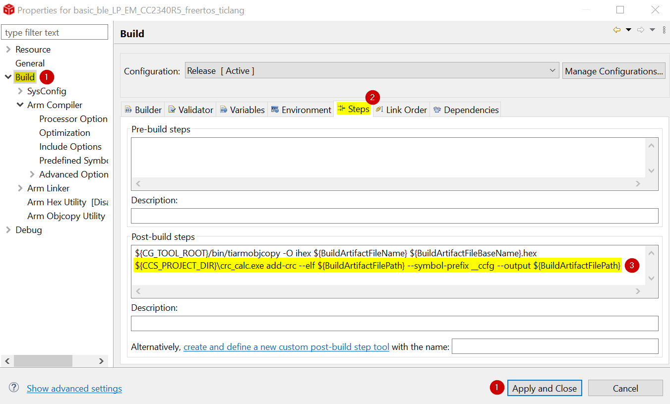
Figure 148. Adding Post Build Steps for CRC Tool.
Build the project. You should be able to see the description of the actions being executed by the
crc_toolin the console when building.
If there is no need to use CCS and the intention is to only add CRC values to an ELF file, the following steps can be used:
Add the symbols to the
.cmdfile.Go to the CRC tool directory (
<SDK>\tools\common\crc_tool) and open the command prompt.In order to calculate the CRC values for the ELF file named
output.outrun the following command:
.\crc_tool.exe patch-image --elf output.out --symbol-prefix __my_prefix --output output.outNote
Please make sure that you are using the same prefix inside the ELF file as the one declared below (in our example:
__my_prefix) with the--symbol-prefix.
Table 30. The following command line options are available for patch-image:¶Name
Usage
‘–elf {file location}’
Specify location of input file
‘–symbol-prefix’
Specify prefix of begin / end symbols in ELF file
‘–output {file_name}’
Specify name of output file
Generate a User Record binary file with CRC
The User Record can be used to program unique ID specific to each device in their own defined format.
A total of 124 + 4(CRC) bytes are available for the user record. In addition,
the generated user record binary can be flashed on the production line even with debug locked and without
affecting the actual application.
Please consider the following for the input text (.txt) file:
The input text file must contain one or more valid hex values (
0xprefix is optional).Separate integers are separated by whitespace or newlines.
Each value must consist of two hexadecimal characters. For instance,
1is invalid,01is valid.The total length of all values can be at most 124 bytes.
Comments can be added with
#, and blank lines are ignored.
Warning
Currently only text files (.txt) are supported.
Please consider the following for the output binary (.bin) file:
The output file will be a 128 byte binary file, containing integers in the same order as the input data, with the first integer at the lowest address.
The output data will be right-padded with zeros to a total of 124 bytes. After the 124 bytes of content there will be four CRC bytes.
Each integer will be written to the file using little endian.
In order to generate a binary file named output.bin with input data and CRC from a text
file named input.txt, the following command line invocation can be used after opening a
command prompt inside the CRC Tool directory (\tools\common\crc_tool):
.\crc_tool.exe generate-user-record --user-record-file input.txt --output output.bin# integer #1 #2 #3 #4 #5 0x0123456789ABCDEF EF 0123 0000 0x0ABCDE # Newline can also be used as divider # Integer #6 0xBCDE
Table 31. The following command line options are available for generate-user-record:¶Name
Usage
‘–user-record-file’
Specify location of input file
‘–output {file_name}’
Specify name of output file
Listing 157. Example of output.binfile which you can see has been padded to 124 bytes, plus 4 bytes CRC.¶# ------------------- hexdump -C <output_file> -------------# # 00000000 ef cd ab 89 67 45 23 01 ef 23 01 00 00 de bc 0a # 00000010 de bc 00 00 00 00 00 00 00 00 00 00 00 00 00 00 # 00000020 00 00 00 00 00 00 00 00 00 00 00 00 00 00 00 00 # ... # 00000070 00 00 00 00 00 00 00 00 00 00 00 00 52 14 8f e6 # 00000080
Once you have the binary file, it is possible to flash it into the User Record using UNIFLASH following the same steps described in Write into the User Record while in Production.