Introduction to Channel Sounding
This chapter serves as a guide to the Texas Instruments Channel Sounding feature including application implementation, drivers, and middle layers of the stack. Bluetooth 6.0 specification Channel Sounding extends the capabilities of Bluetooth-based ranging beyond traditional RSSI and direction finding (DF) methods, enabling more accurate and cost-effective ranging designs.
The guide will cover the main principles of the Channel Sounding process, the process of adding Channel Sounding to a project, and an out of the box example project available within the SimpleLink Low Power F3 SDK.
The Channel Sounding chapters will cover:
Channel Sounding overview, discussing the what and why (see Channel Sounding Overview)
Channel Sounding APIs (see BLE Stack API Reference)
Enable Channel Sounding Demonstration (see How to enable Channel Sounding example)
The CC23xx or CC27xx LaunchPad allows for quick and easy development of BLE applications, such as Channel Sounding. To run the Channel Sounding example, you will need two TI CC23xx or CC27xx.
Note: To run the CS demo, one must use CC27xx as car node in order to support distance calculation.
Channel Sounding Overview
What is Channel Sounding? Bluetooth Channel Sounding (CS), introduced in the Bluetooth 6.0 specification, enables high-accuracy distance measurement between two BLE devices using phase-based ranging (PBR). This technique estimates the distance by measuring the phase difference between a received unmodulated tone and the device’s local oscillator (LO) across multiple RF frequencies in the 2.4 GHz band. Both devices—the initiator and the reflector—exchange tones and record phase information. These phase differences, when plotted against frequency, yield a curve whose slope directly corresponds to the physical distance between devices. Advanced signal processing helps correct for multipath interference, enhancing precision even in complex radio environments.
Why is Channel Sounding Important? Channel Sounding delivers high-level distance accuracy without needing external infrastructure, making it ideal for real-time location systems (RTLS), car access, and secure proximity-based services. It also introduces built-in security mechanisms like random frequency hopping, Round Trip Time (RTT) validation, and attack detection metrics (NADM) to defend against spoofing or relay attacks. Importantly, it integrates efficiently with existing Bluetooth LE protocols, supporting low-power, low-cost, and scalable deployment across consumer, industrial, and automotive applications.
Two BLE supported devices are needed for Channel Sounding for this version of the SimpleLink Low Power F3 SDK.
Car Node
Key Node
The car node is the initiator device and the key node is the reflector device. The initiator is the device that is in control of the channel sounding configuration, synchronization, and begins each channel sounding subevent. Firstly, Mode 0 steps are sent from the initiator to the reflector. The Mode 0 steps synchronize the reflector to the initiators configuration and sets up the timing for the unmodulate tones, or subevents. Next, Mode 1, 2, or 3 steps can be completed. These steps include (RTT), (PBR) or a combination of both. Each step is an unmodulated tone sent between the initiator and the reflector device. The phase change or the time of flight of the tone is then used to calculate the distance, and/or detect spoofing, or man in the middle attacks.
How to enable Channel Sounding example
Channel sounding example works using CCS and Python:
CCS is used to flash one CC23xx or CC27xx with an initiator code and the second with one with a reflector code.
Python is used to control car node and plot results of CS procedure.
The following section will go through the SW flow behind TI’s CS demo.
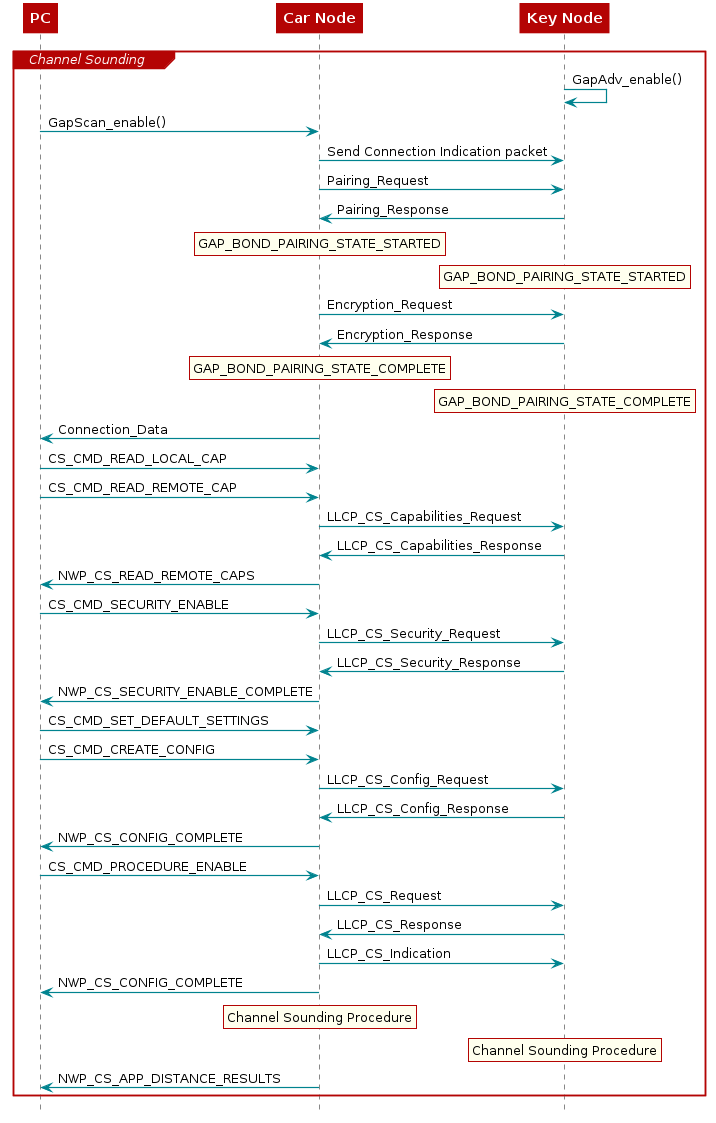
Figure 125. Channel Sounding Example Project Software Flow
Prerequisites
Hardware:
2 x SimpleLink CC23xx or CC27xx LaunchPad Target
2 x SimpleLink™ LaunchPad™ XDS110 Debugger
2 x USB cable
(Optional) 1 x Battery Pack for Reflector
Software:
TI Code Composer Studio (CCS)
Prepare CCS and Python environment
1. For the initiator node, import <SDK>/examples/rtos/LP_EM_CC2745R10/ble/car_node and set the example to initiate a pairing request within Bond Manager. Procedure to do this is described below.
Flash the car_node project onto one of the two CC23xx or CC27xx devices and keep it connected to your PC. The COM port of the ble_device_car_node_with_distance.py script should be set to the COM port of the car node.
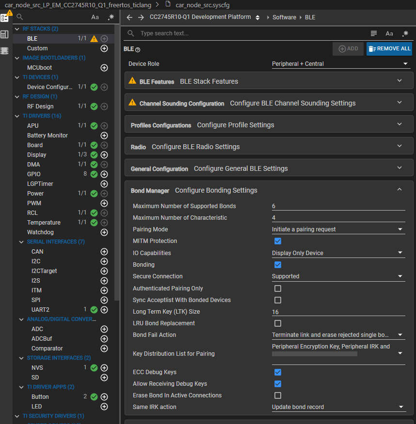
Figure 126. Configure Car Node to Initiate Pairing
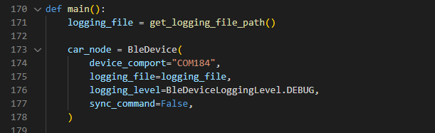
Figure 127. Configure COM Port for Car Node in Python
For reflector node, import
<SDK>/examples/rtos/LP_EM_CC2745R10/ble/key_node. Flash the key_node project onto the second CC23xx or CC27xx device. The reflector does not need to remain connected to your PC. It only needs to be powered.
Note: Advertising data in the key node project is used by python. If it is changed in CCS, make sure to change it in python script too.
(Optional) To configure 2x2 antenna setup for both CC23xx or CC27xx:
Python:
Go to
<SDK>/tools/ble/ble_agent/examples/ble_device_car_node_with_distance.py. Change in cs_set_procedure_params and cs_set_procedure_params_repeat “aci” from 0 to 7 and “preferred_peer_antenna” from 0b0001 to 0b0011;To use other antenna configurations, refer to the ACI map below. Additionally, the preferred_peer_antenna bitmap will dictate the number of antennas on the peer (reflector).
ACI
Ant Config
ACI=0
1x1
ACI=1
2x1
ACI=2
3x1
ACI=3
4x1
ACI=4
1x2
ACI=5
1x3
ACI=6
1x4
ACI=7
2x2
Note: The antenna configurations above are oriented initiator x reflector.
CCS:
Go to Syscfg -> RF STACKS -> BLE -> Channel sounding configuration -> Number of Antennas. Select 2 antennas, and configure the Antenna Mux Bitmap 0xC6. For different antenna configurations, refer to the note within the Antenna Mux Bitmap section of SysConfig.
Syscfg -> TI DRIVERS -> RCL -> RCL Observable -> Additional RF GPIO Signals. Add PBEGPO2 and PBEGPO3.
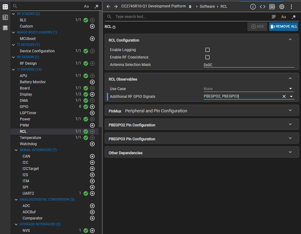
Figure 128. Configure PBEGPOs for Multiple Antennas
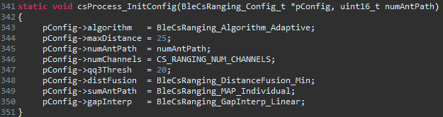
4. (Optional) To configure algorithm, max distance, QQ3 threshold, Distance Fusion, antenna path summation, and gap interpolation, navigate to the Car Node project in CCS -> app folder -> inc folder -> app_cs_process.c file -> csProcess_InitConfig.
Note: Max distance measurable = maxDistance / 2
Install Python 3.10.11
Note: Python 3.10 should be installed at C:\Python310
During installation select “Add Environment Variable”, otherwise you can add it later, shown in the images below:
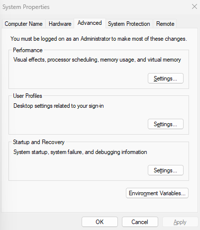
Figure 129. Open System Properties
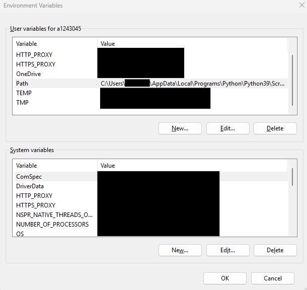
Figure 130. Navigate to Environment Variables

Figure 131. Edit User Environment Variables
Open a command line tool such as Windows Power Shell and install and activate virtual environment. In case your network is behind a proxy, use the proxy command shown.
1    cd <ble_agent folder (SDK/tools/ble/ble_agent)>
2    c:\Python310\python.exe -m pip install virtualenv [--proxy <www.proxy.com>]
3    c:\Python310\python.exe -m venv .venv
4    .venv\Scripts\activate
Setup external packages in case your network is behind a proxy, use [–proxy]
1    python -m pip install --upgrade pip [--proxy <www.proxy.com>]
2    pip install --upgrade wheel [--proxy <www.proxy.com>]
3    pip install -r requirements.txt [--proxy <www.proxy.com>]
How to run Channel Sounding example
Python
Execute Python Script in the previously configured environment using:
1    cd \simplelink_lowpower_f3_source_sdk_9_10_00_70_eng\tools\ble\ble_agent
2    .venv\Scripts\activate
3    cd examples
4    python ble_device_car_node_with_distance.py
The script will automatically initiate a connection between the car node and key node and start a CS procedure. See an example of the output below:
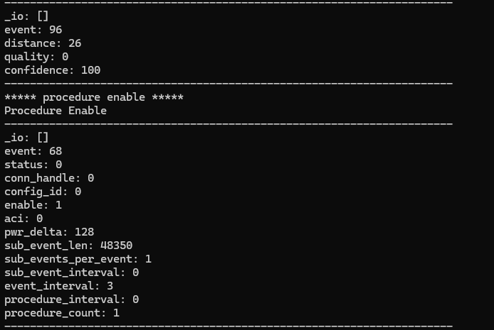
Figure 132. Distance Output in Terminal