

|
|
SPI driver implementation for a EUSCI peripheral on MSP432 using the micro DMA controller.
The SPI header file should be included in an application as follows:
Refer to SPI.h for a complete description of APIs & example of use.
This SPI driver implementation is designed to operate on a EUCSI controller in SPI mode using a micro DMA controller.
This SPI controller supports 4 phase & polarity formats. Refer to the device specific data sheets & technical reference manuals for specifics on each format.
The SPI driver can be used in 3-pin or 4-pin mode. When in 4-pin mode the hardware manages a pin as the chip select. In 3-pin mode it is the application's responsibility to assert and de-assert a GPIO pin for chip select purposes.
| Chip select type | SPI_MASTER mode | SPI_SLAVE mode |
|---|---|---|
| Hardware chip select | No action is needed by the application to select the peripheral. | See the device documentation on it's chip select requirements. |
| Software chip select | The application is responsible to ensure that correct SPI slave is selected before performing a SPI_transfer(). | Up to the application's implementation. |
The EUSCI controller only supports 8-bit data frames.
| dataSize | buffer element size |
|---|---|
| 8 bits | uint8_t |
DMA use in this driver varies based on the SPI_TransferMode set when the driver instance was opened. If the driver was opened in SPI_MODE_CALLBACK, all transfers make use of the DMA regardless of the amount of data.
If the driver was opened in SPI_MODE_BLOCKING, it verifies the amount of data frames to be transfered exceeds the SPIMSP432DMA_HwAttrsV1.minDmaTransferSize before performing a transfer using the DMA. SPIMSP432DMA_HwAttrsV1.minDmaTransferSize allows users to set a minimum amount of data frames a transfer must have to perform a transfer using the DMA. If the amount of data is less than this limit, the driver performs a polling transfer (unless the device is a slave with a timeout configured). This feature is provided for situations where there is little data to be transfered & it is more efficient to simply perform a polling transfer instead of configuring the DMA & waiting until the task is unblocked.
The MSP432 DMA controller has 4 interrupt vectors to handle all DMA related IRQ. Due to the "shared" nature of the DMA interrupts, this driver implementation requires each SPI instance to explicitly use a single DMA interrupt. It is up to the application to ensure no two peripherals are configured to respond to a given DMA interrupt at any moment.
The DMA controller only supports data transfers of up to 1024 data frames, so large amounts of data will be split & transfered accordingly. Each SPI driver instance requires 2 DMA channels (Tx and Rx) to operate.
Ensure that the SPI_Transaction.rxBuf and SPI_Transaction.txBuf point to memory that is accessible by the DMA.
A uint8_t scratch buffer is used to allow SPI_Transaction where txBuf or rxBuf are NULL. Rather than requiring txBuf or rxBuf to have a dummy buffer of size of the transfer count, a single DMA accessible uint8_t scratch buffer is used. When txBuf is NULL, an internal scratch buffer is initialized to the SPIMSP432DMA_HwAttrsV1.defaultTxBufValue so the DMA will send some known value.
#include <stdint.h>#include <ti/devices/DeviceFamily.h>#include <ti/drivers/dpl/HwiP.h>#include <ti/drivers/dpl/SemaphoreP.h>#include <ti/drivers/Power.h>#include <ti/drivers/SPI.h>#include <ti/drivers/dma/UDMAMSP432.h>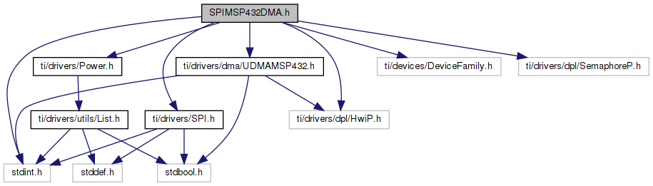
Go to the source code of this file.
Data Structures | |
| struct | SPIMSP432DMA_HWAttrsV1 |
| SPIMSP432DMA Hardware attributes These fields, with the exception of intPriority, are used by driverlib APIs and therefore must be populated by driverlib macro definitions. For MSP432 driverlib these definitions are found in: More... | |
| struct | SPIMSP432DMA_Object |
| SPIMSP432DMA Object. More... | |
Macros | |
| #define | SPIMSP432DMA_PIN_NO_CONFIG (0x0000FFFF) |
| SPIMSP432DMA_PIN_NO_CONFIG can be used to inform the SPIMSP432DMA driver that a pin should not be configured for use in the SPI bus. If the simoPin, somiPin or stePin is set to SPIMSP432DMA_PIN_NO_CONFIG in the SPIMSP432DMA_HWAttrs, the pin is not configured to SPI functionality during SPI_open() and the pin can be used for another function. The clkPin cannot be set to SPIMSP432DMA_PIN_NO_CONFIG; the clock signal is always required during communication & must be driven by the SPI bus master. More... | |
Typedefs | |
| typedef struct SPIMSP432DMA_Object * | SPIMSP432DMA_Handle |
Variables | |
| const SPI_FxnTable | SPIMSP432DMA_fxnTable |
| #define SPIMSP432DMA_PIN_NO_CONFIG (0x0000FFFF) |
SPIMSP432DMA_PIN_NO_CONFIG can be used to inform the SPIMSP432DMA driver that a pin should not be configured for use in the SPI bus. If the simoPin, somiPin or stePin is set to SPIMSP432DMA_PIN_NO_CONFIG in the SPIMSP432DMA_HWAttrs, the pin is not configured to SPI functionality during SPI_open() and the pin can be used for another function. The clkPin cannot be set to SPIMSP432DMA_PIN_NO_CONFIG; the clock signal is always required during communication & must be driven by the SPI bus master.
Prevent all these port defines from cluttering doxygen
Setting pins to SPIMSP432DMA_PIN_NO_CONFIG can be useful in the following situations:
| typedef struct SPIMSP432DMA_Object * SPIMSP432DMA_Handle |
| const SPI_FxnTable SPIMSP432DMA_fxnTable |