Introduction
This module is a study of the Angle of Arrival (AoA). AoA is a technique for finding the direction that an incoming packet is coming from. The estimated time to complete this lab is between 1-2 hours. It is assumed that the reader has a basic knowledge of embedded C tool chains and general C programming concepts.
This lab is based on the rtls_master, rtls_slave and rtls_passive projects that are part of
the SimpleLink™ CC2640R2 SDK.
First, the lab will cover an overview on how to get started with the AoA projects. Subsequent tasks of this lab will guide the user on how to customize these projects in order to answer most of the common AoA questions.
Prerequisites
Other SimpleLink Academy Labs
- Completion of Realtime Localization System Introduction
Required Training
It is required that users complete all steps of the RTLS Introduction lab before moving on to the Angle of Arrival lab. It is also assumed that the user has already installed the software, setup the hardware, and read the recommended chapters covered by the introduction lab. For brevity, only new content will be listed here.
Software for desktop development
- Required tools and version are listed in the Release Notes
- SimpleLink™ CC2640R2 SDK
Hardware
This module requires the following kits:
- 3x CC2640R2-LAUNCHXL
- 1x BOOSTXL-AoA
Getting started with AoA booster pack
Getting started – Desktop
Install the Software
This lab requires that you have completed all the steps in the RTLS Introduction lab. This means that you must have
- CC2640R2 SDK installed
- Working Python environment
- Modified
rtls_example.pyscript that sets up an RTLS network.
Introduction to AoA
Bluetooth Core Specification Version 5.1 introduces AoA/AoD which are
covered under Direction Finding Using Bluetooth Low Energy Device section.
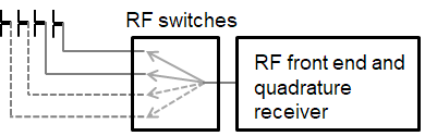
AoA is for receivers that have RF switches, multiple antennas, can switch antennas and capture I/Q samples when receiving direction finding packets.
AoD is for transmitters that have RF switches, multiple antennas and can switch antennas when transmitting direction finding packets. And recieivers only have one antenna but can capture I/Q samples when receiving direction finding packets.
| Direction Finding Method | Transmitter | Receiver |
|---|---|---|
| AoA | Single antenna, transmit CTE | Multiple antennas, RF switches, can switches antennas while capture I/Q data of the CTE |
| AoD | Multiple antennas, RF switches, transmit CTE while switching antennas | Single antenna, can capture I/Q data of the CTE |
On top of that, the Bluetooth Core Specification version 5.1 specifies the following states can support sending direction finding packets:
- Periodic advertising; also called
Connectionless CTE - Connection; also called
Connection CTE
The theory behind AoA/AoD and Connectionless/Connection CTE is the same, therefore in this SimpleLink Academy training, we will only focus on Connection CTE AoA.
We will explain the AoA theory first and the walk through our SimpleLink CC2640R2F SDK offering.
AoA measurement is typically a 3-step process:
- Collect phase information by sampling the I/Q
- Calculate the phase difference among the antennas
- Covert the phase difference into Angle of Arrival
1. Collect phase information by sampling the I/Q
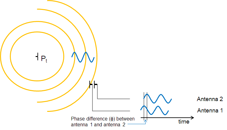
When two (or more) antennas are placed at a given distance apart from each other, their received RF signals will have a phase difference that is proportional to the difference between their respective distances from the transmitter.
Typically, the signal from one antenna will be a delayed version of the signal from the other antenna. If they are sufficiently close (less than Λ(wavelength)/2 between phase centers), you can always determine which is closest to the transmitter.
These path length differences will depend on the direction of the incoming RF waves relative to the antennas in the array. In order to measure the phase difference accurately, the radio wave packet must contain a section of constant tone with whitening disabled where there are no phase shifts caused by modulation.
Constant Tone Extension (CTE)
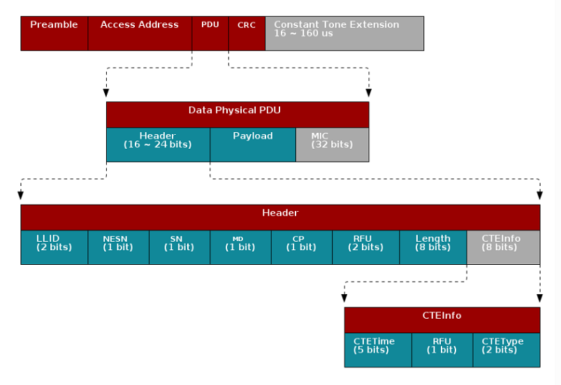
The constant tone extension is a section of consecutive 1's without whitening, which is effectively a +250kHz wave on top of the carrier wave. In the Bluetooth Core Specification Version 5.1, both periodic advertising packets and connection packets can contain a constant tone extension(CTE) after the CRC. The CTE can only be sent using uncoded PHY.
2. Calculate the phase difference among the antennas
Phase Difference (Φ) is measured by connecting at least two antennas to the same receiver sequentially (more antennas can be added).
In order to get a good estimate of Φ (phase), all other intentional phase shifts in the signal should be removed. Connection CTE AoA solution achieves this by adding CTE at the end of packets.
 |
|---|
| Connection CTE Packet Format |
Data Physical Packet format
The grey colored part of the packet shown above means
it's optional. The Constant Tone Extension is only enabled when the CP bit
in the Data Physical PDU header is set. The detail of the Constant Tone
Extension is then specified by the CTEInfo field in the in the Data
Physical PDU.
This gives the receiver time to synchronize the demodulator first, and then store the I/Q samples from the CTE into radio RAM. The I/Q data is then extracted by the application layer.
I/Q samples are used to estimate phase difference among antennas. When the receiver gets AoA packets, the RF core will trigger an event that will lead to start of the antenna switching. The RF core will start sampling the I/Q data after the guard period of the CTE and the sampled data will be stored in the radio RAM.
By comparing the I/Q data collected from different antennas, users can get the relative phase difference among antennas.
3. Convert the phase difference into Angle of Arrival
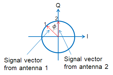
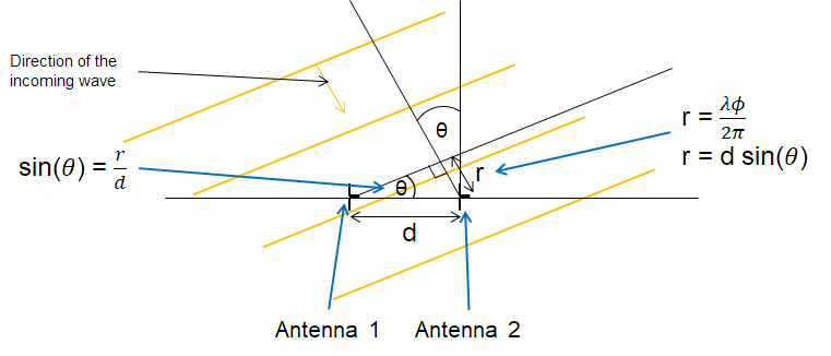
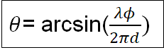
Last step is converting the phase shift (Φ) back to AoA (Θ). Keep in mind if Φ is negative, this means that antenna 2 is ahead of antenna 1 and the Θ.
The angle between the incident wave and antenna array is Θ. Base on the picture below we know that the sin(Θ) = r/d, and d is the distance between antenna 1 and antenna 2 which is known. Then all we need to find out is r.
r is the distance to antenna 2 that the incident wave needs to travel after arriving at antenna 1. We have found that the phase difference between antenna 1 and antenna 2 is Φ, so the extra distance r is equal to wavelength of the incoming signal * Φ/(2Π).
r= Λ* Φ/(2Π)
Note
In rtls_passive example, you might notice that step 3 is not implemented.
The reason is simply because by step 2 using our
BOOSTXL-AoA we already have
linear result from +/-90 degree using antenna pair[1,2] and pair[2,3].
Therefore all we need is to have a look up table to do the fine tuning.
This saves computation time/current consumption compared to doing another arcsin function.
We also tried to do arcsin, but the result is pretty much the same as adding gain and offset after step 2.
What technique does AoA use to identify the direction of incident wave?
Task 1 – Running the AoA application
The SimpleLink™ CC2640R2 SDK
has three examples dedicated to performing AoA (rtls_master,
rtls_slave and rtls_passive). This section will explain how those
examples works together.
Here we assume that you have already finished Realtime Localization System Introduction and got the demo running.
The rtls_master and rtls_slave will form a BLE connection. After
establishing the connection, rtls_master will send connection information
through UART to PC and then then node manager will pass this piece of
information to rtls_passive which can then track the connection.
Next, the node manager sets up AoA parameters for master and passive
and then master will send a packet over the air to slave
to setup the CTE time.
After that, the rtls_master will send a start AoA request over the air to
the rtls_slave and to rtls_passive over wire, then rtls_slave will
append CTE at the end of every connection packet.
rtls_passive can the do I/Q sampling and calculate angles base on the ConnectionCTE packets.
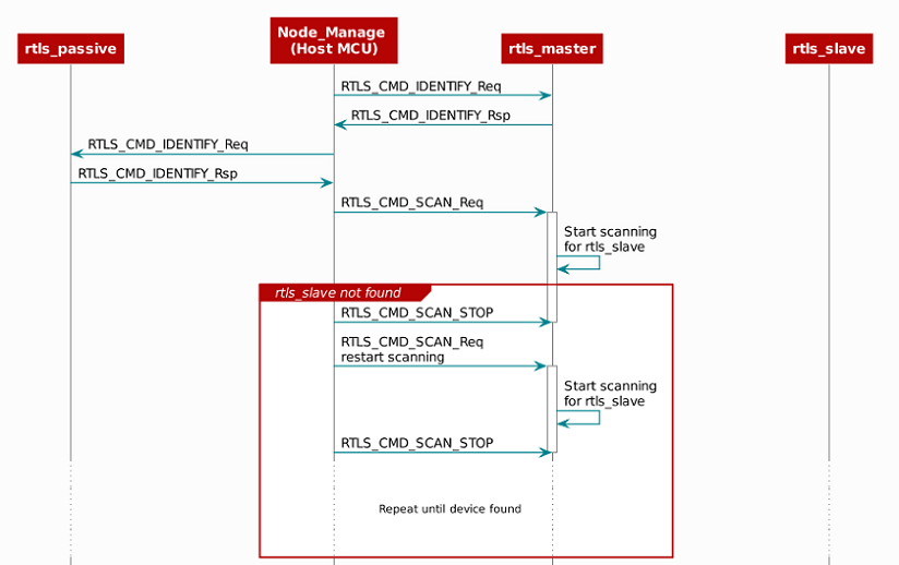
The sequence diagram below illustrates the whole process of how out of box examples work.
 |
|---|
| Initialization and scanning |
 |
|---|
| After finding rtls_slave |
Task 2 – Modify AoA application to use only one antenna array
The out of box SimpleLink™ CC2640R2 SDK
rtls_passive example will stay on one antenna array when receiving
one AoA packet and
then change to another antenna array for the next AoA packet.
Following code contains the logic for antenna array switching.
  // Switch ant array
  if (gAoaReport.antConfig == antA1Config)
  {
    gAoaReport.antConfig = antA2Config;
    gAoaReport.antResult = antA2Result;
  }
  else if (gAoaReport.antConfig == antA2Config)
  {
    gAoaReport.antConfig = antA1Config;
    gAoaReport.antResult = antA1Result;
  }
  else
  {
    // Should not get here
    return;
  }
AOA.c::AOA_setupNextRun()
The angle is then decided once both arrays have received AoA packets and judge by the rssi value of the received packet to decide whether the application should trust angle derived from array 1 or array 2.
    // Signal strength is higher on A1 vs A2
    if (antA1Result->rssi > antA2Result->rssi)
    {
        // Use AoA from Antenna Array A1
        AoA_ma.array[AoA_ma.idx] = AoA_A1;
        AoA_ma.currentAoA = AoA_A1;
        AoA_ma.currentAntennaArray = 1;
        AoA_ma.currentRssi = antA1Result->rssi;
        AoA_ma.currentSignalStrength = signalStrength_A1;
        AoA_ma.currentCh = antA1Result->ch;
        AoA.currentangle = AoA_A1;
    }
    // Signal strength is higher on A2 vs A1
    else
    {
        // Use AoA from Antenna Array A2
        AoA_ma.array[AoA_ma.idx] = AoA_A2;
        AoA_ma.currentAoA = AoA_A2;
        AoA_ma.currentAntennaArray = 2;
        AoA_ma.currentRssi = antA2Result->rssi;
        AoA_ma.currentSignalStrength = signalStrength_A2;
        AoA_ma.currentCh = antA2Result->ch;
        AoA.currentangle = AoA_A2;
    }
rtls_ctrl_aoa.c::RTLSCtrl_estimateAngle()
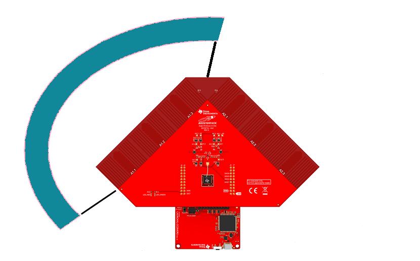
However, this might not be how you want to design or utilize your antennas. Therefore, this section we will walk you through the changes if you only want one antenna array, like Automotive Bluetooth low energy car access satellite node reference design
We will go from this configuration:
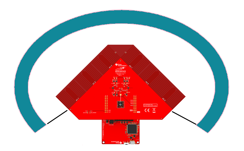
To this configuration (using antenna array #1):
The steps below will guide you through the process of removing one of the antenna
array. For this example we will be removing A2, but these steps are also
applicable in case that A1 needs to be removed.
- Start from the
rtls_passive_cc2640r2lp_appproject and rename it tortls_passive_cc2640r2lp_a1_app - Delete the files
ant_array2_config_boostxl_rev1v1.candant_array2_config_boostxl_rev1v1.hfrom the project Comment out all of the antenna array 2 dependencies from
AOA.c//Comment out all the followings lines //line 64 #include "ant_array2_config_boostxl_rev1v1.h" //line 169 and line 171 AoA_AntennaConfig *antA2Config = &BOOSTXL_AoA_Config_ArrayA2; AoA_AntennaResult *antA2Result = &BOOSTXL_AoA_Result_ArrayA2; //line 399, 402 and 405 in AOA_init() BOOSTXL_AoA_AntennaPattern_A2_init(); antA2Result->updated = false; aoaResults->antA2Result = antA2Result; //line 730~733 in AOA_getActiveAnt() else if (gAoaReport.antConfig == antA2Config) { return 2; } //line 756~760 in AOA_setupNextRun() else if (gAoaReport.antConfig == antA2Config) { gAoaReport.antConfig = antA1Config; gAoaReport.antResult = antA1Result; }Change the following lines in AOA.c to take antenna 1 instead.
//line 753 and 754 in AOA_setupNextRun()
// Switch ant array
if (gAoaReport.antConfig == antA1Config)
{
 gAoaReport.antConfig = antA1Config;
 gAoaReport.antResult = antA1Result;
}
c
Replace the content of RTLSCtrl_postProcessAoa in
rtls_ctrl_aoa.cwith the provided code snippet. What we have done here is to remove all the antenna array 2 dependency.void RTLSCtrl_postProcessAoa(rtlsAoa_t *aoaControlBlock, int8_t rssi, uint8_t channel) { uint8_t status; if (aoaControlBlock->aoaParams.aoaRole == AOA_ROLE_PASSIVE) { status = AOA_postProcess(rssi, channel); if (status) { switch(aoaControlBlock->aoaParams.resultMode) { case AOA_MODE_ANGLE: { AoA_Sample aoaTempResult; rtlsAoaResultAngle_t aoaResult; AOA_getPairAngles(); { gAoaResults.antA1Result->updated = false; const AoA_AntennaResult *antA1Result = gAoaResults.antA1Result; aoaTempResult = RTLSCtrl_estimateAngle(antA1Result); aoaResult.angle = aoaTempResult.angle; aoaResult.antenna = aoaTempResult.antenna; aoaResult.rssi = aoaTempResult.rssi; aoaResult.channel = aoaTempResult.channel; RTLSHost_sendMsg(RTLS_CMD_AOA_RESULT_ANGLE, HOST_ASYNC_RSP, (uint8_t *)&aoaResult, sizeof(rtlsAoaResultAngle_t)); } } break; case AOA_MODE_PAIR_ANGLES: { rtlsAoaResultPairAngles_t aoaResult; int16_t *pairAngle; uint8_t antenna; AOA_getPairAngles(); if (gAoaResults.antA1Result->updated == true) { pairAngle = gAoaResults.antA1Result->pairAngle; gAoaResults.antA1Result->updated = false; antenna = 1; } else { // Should not get here return; } aoaResult.rssi = rssi; aoaResult.channel = channel; aoaResult.antenna = antenna; for (int i = 0; i < AOA_NUM_ANTENNAS; i++) { aoaResult.pairAngle[i] = pairAngle[i]; } RTLSHost_sendMsg(RTLS_CMD_AOA_RESULT_PAIR_ANGLES, HOST_ASYNC_RSP, (uint8_t *)&aoaResult, sizeof(rtlsAoaResultPairAngles_t)); } break; case AOA_MODE_RAW: { rtlsAoaResultRaw_t *aoaResult; uint16_t numAoaSamples; uint16_t samplesToOutput; AoA_IQSample *pIter; aoaResult = RTLSCtrl_malloc(sizeof(rtlsAoaResultRaw_t) + (MAX_SAMPLES_SINGLE_CHUNK * sizeof(AoA_IQSample))); pIter = AOA_getRawSamples(); // If the array is not empty if (pIter != NULL && aoaResult != NULL) { // Calculate how many samples we will be outputting numAoaSamples = AOA_calcNumOfCteSamples(aoaControlBlock->aoaParams.cteTime, aoaControlBlock->aoaParams.cteScanOvs, aoaControlBlock->aoaParams.cteOffset); aoaResult->channel = channel; aoaResult->rssi = rssi; aoaResult->samplesLength = numAoaSamples; aoaResult->antenna = AOA_getActiveAnt(); aoaResult->offset = 0; do { // If the remainder is larger than buff size, tx maximum buff size if (aoaResult->samplesLength - aoaResult->offset > MAX_SAMPLES_SINGLE_CHUNK) { samplesToOutput = MAX_SAMPLES_SINGLE_CHUNK; } else { // If not, then output the remaining data samplesToOutput = aoaResult->samplesLength - aoaResult->offset; } // Copy the samples to output buffer for (int i = 0; i < samplesToOutput; i++) { aoaResult->samples[i] = pIter[i]; } RTLSHost_sendMsg(RTLS_CMD_AOA_RESULT_RAW, HOST_ASYNC_RSP, (uint8_t *)aoaResult, sizeof(rtlsAoaResultRaw_t) + (sizeof(AoA_IQSample) * samplesToOutput)); aoaResult->offset += samplesToOutput; pIter += MAX_SAMPLES_SINGLE_CHUNK; } while (aoaResult->offset < aoaResult->samplesLength); } if (aoaResult) { RTLSUTIL_FREE(aoaResult); } } break; default: break; } // Once all post processing is complete, set up the next run AOA_setupNextRun(); } } }rtls_ctrl_aoa.c:: RTLSCtrl_postProcessAoa
Replace the content of RTLSCtrl_estimateAngle in
rtls_ctrl_aoa.cwith the provided code snippet. What we have done here is to remove all the antenna array 2 dependency and modify the function call to take one array only when making an angle decision.//line 122 under local function section AoA_Sample RTLSCtrl_estimateAngle(const AoA_AntennaResult *antA1Result);// The function itself AoA_Sample RTLSCtrl_estimateAngle(const AoA_AntennaResult *antA1Result) { AoA_Sample AoA; static AoA_movingAverage AoA_ma; uint8_t AoA_ma_size = sizeof(AoA_ma.array) / sizeof(AoA_ma.array[0]); // Calculate AoA for each antenna array const int16_t AoA_A1 = ((antA1Result->pairAngle[0] + antA1Result->pairAngle[1]) / 2) + antA1Result->channelOffset[antA1Result->ch]; // Calculate average signal strength const int16_t signalStrength_A1 = (antA1Result->signalStrength[0] + antA1Result->signalStrength[1]) / 2; // Use AoA from Antenna Array A1 AoA_ma.array[AoA_ma.idx] = AoA_A1; AoA_ma.currentAoA = AoA_A1; AoA_ma.currentAntennaArray = 1; AoA_ma.currentRssi = antA1Result->rssi; AoA_ma.currentSignalStrength = signalStrength_A1; AoA_ma.currentCh = antA1Result->ch; AoA.currentangle = AoA_A1; // Add new AoA to moving average AoA_ma.array[AoA_ma.idx] = AoA_ma.currentAoA; // Calculate new moving average AoA_ma.AoAsum = 0; for(uint8_t i = 0; i < AoA_ma_size; i++) { AoA_ma.AoAsum += AoA_ma.array[i]; } AoA_ma.AoA = AoA_ma.AoAsum / AoA_ma_size; // Update moving average index if(AoA_ma.idx >= (AoA_ma_size - 1)) { AoA_ma.idx = 0; } else { AoA_ma.idx++; } // Return results AoA.angle = AoA_ma.AoA; AoA.rssi = AoA_ma.currentRssi; AoA.signalStrength = AoA_ma.currentSignalStrength; AoA.channel = AoA_ma.currentCh; AoA.antenna = AoA_ma.currentAntennaArray; return AoA; }rtls_ctrl_aoa.c::RTLSCtrl_estimateAngle
Task 3 – Modify AoA application to use only two antennas
Now we have successfully moved from using 2 antenna arrays to 1. We will use the example from Task 2 as the baseline and make the proper changes so we only use 2 antennas from the antenna array 1.
Task 2 is using all 3 antennas from
A1: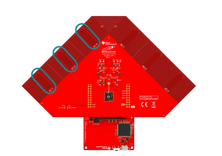
And the end goal is using the following:
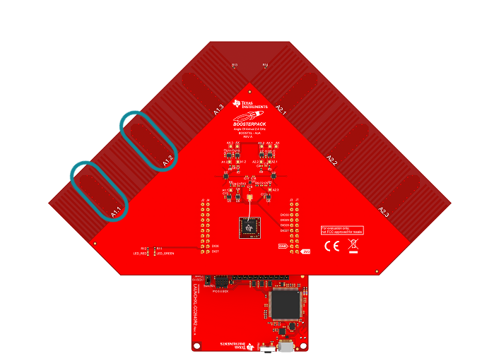
The following steps will guide you through this process:
Comment out the following in ant_array1_config_boostxl_rev1v1.c.
 //line 57
 #define AOA_Ax_ANT3    AOA_PIN(IOID_30)

 //line 131~144
 {// v23
  .a = 1,
  .b = 2,
  .sign = 1,
  .offset = -5,
  .gain = 0.9,
 },
 {// v13
  .a = 0,
  .b = 2,
  .sign = 1,
  .offset = -20,
  .gain = 0.50,
 },
Replace the antenna toggling patten in ant_array1_config_boostxl_rev1v1.c with the provided pattern.
AoA_Pattern antennaPattern_A1 = {
 .numPatterns = 32,
 .initialPattern = AOA_A1_SEL | AOA_Ax_ANT2,
 .toggles =
 {
  AOA_A1_SEL | AOA_Ax_ANT1, // A1.1
  AOA_A1_SEL | AOA_Ax_ANT2, // A1.2
  AOA_A1_SEL | AOA_Ax_ANT1, // A1.1
  AOA_A1_SEL | AOA_Ax_ANT2, // A1.2
  AOA_A1_SEL | AOA_Ax_ANT1, // A1.1
  AOA_A1_SEL | AOA_Ax_ANT2, // A1.2

  AOA_A1_SEL | AOA_Ax_ANT1, // A1.1
  AOA_A1_SEL | AOA_Ax_ANT2, // A1.2
  AOA_A1_SEL | AOA_Ax_ANT1, // A1.1
  AOA_A1_SEL | AOA_Ax_ANT2, // A1.2
  AOA_A1_SEL | AOA_Ax_ANT1, // A1.1
  AOA_A1_SEL | AOA_Ax_ANT2, // A1.2

  AOA_A1_SEL | AOA_Ax_ANT1, // A1.1
  AOA_A1_SEL | AOA_Ax_ANT2, // A1.2
  AOA_A1_SEL | AOA_Ax_ANT1, // A1.1
  AOA_A1_SEL | AOA_Ax_ANT2, // A1.2
  AOA_A1_SEL | AOA_Ax_ANT1, // A1.1
  AOA_A1_SEL | AOA_Ax_ANT2, // A1.2

  AOA_A1_SEL | AOA_Ax_ANT1, // A1.1
  AOA_A1_SEL | AOA_Ax_ANT2, // A1.2
  AOA_A1_SEL | AOA_Ax_ANT1, // A1.1
  AOA_A1_SEL | AOA_Ax_ANT2, // A1.2
  AOA_A1_SEL | AOA_Ax_ANT1, // A1.1
  AOA_A1_SEL | AOA_Ax_ANT2, // A1.2

  AOA_A1_SEL | AOA_Ax_ANT1, // A1.1
  AOA_A1_SEL | AOA_Ax_ANT2, // A1.2
  AOA_A1_SEL | AOA_Ax_ANT1, // A1.1
  AOA_A1_SEL | AOA_Ax_ANT2, // A1.2
  AOA_A1_SEL | AOA_Ax_ANT1, // A1.1
  AOA_A1_SEL | AOA_Ax_ANT2, // A1.2

  AOA_A1_SEL | AOA_Ax_ANT2, // A1.2 stay with antenna 2 at the end
  AOA_A1_SEL | AOA_Ax_ANT2, // A1.2
 }
};
Using different antennas instead of A1.1 and A1.2
Our example code always uses antenna A1.2 or A2.2 to receive packets before the CTE. This is set by the code below
.initialPattern = AOA_A1_SEL | AOA_Ax_ANT2,antennaPattern_A1[] :: ant_array1_config_boostxl_rev1v1.c
Therefore, for users using antennas other than A1.2 or A2.2, you will need to modify the initialPattern too.
Change the AOA_NUM_ANTENNAS to 2 in AOA.h
// line 58
#define AOA_NUM_ANTENNAS 2
The IOs that control the antenna switches are initialized in AOA.c::AOA_openPins Therefore, we need to modify this part of the code since we are using one less IO. Change the pinMask to the following
//line 295 and line 321
pinMask = (1 << IOID_27 | 1 << IOID_28 | 1 << IOID_29 );
Fundamental done
Now the application only uses antenna A1.1 and A1.2! Very well done! And the updated software still works with RTLS_Monitor GUI.
Task 4 – AoA I/Q Samples
Python solution
The python solution for rtls_aoa in exercise 4 is provided at the end of this training.
So far we have worked on the application code to modify the
rtls_passive to work with custom HW. We will now spend some
time looking into the I/Q data.
The reason for checking I/Q data is that different HW design will yield different result which will affect your own angle calculation algorithm. For example, if the rf switches you are using need longer settling time than the ones on BOOSTXL-AoA, then you will need to discard more I/Q samples when doing calculations.
To decide how many I/Q samples you can use, you will need to extract I/Q samples and calculate phase to determine at which samples antennas are changing.
We will first take a look at where I/Q samples are stored and in what format.
I/Q is stored in the radio core RAM(RFC_RAM_BASE + 0x0000C000) and each I/Q pair takes up 32 bits space where I is stored in the lower 16 bits and Q is stored in higher 16 bits.
void AOA_getRxIQ(uint8_t *packetId, AoA_IQSample **samples)
{
  // Should only be called when RF Core is awake
  *packetId = (*((uint8_t*)AOA_PACKET_RAM));
  *samples = packetId ? (AoA_IQSample *)&HWREG(RFC_RAM_BASE + 0x0000C000):NULL;
}
In AOA.c
I/Q samples resolution
I and Q samples only have 13 bits resolution even though they occupy 16 bits space in radio core RAM. Since they only have 13 bits resolution, the maximum and minimum value you will observe as signed integers are [4095, -4096].
To extract the I/Q data from embedded devices over UART, we need to make sure that we have enough time to flush the I/Q data before next AoA packet arrives.
To achieve this, there are two options:
Increase the connection interval. In the
rtls_masterreadme file, it's mentioned that the connection interval should be larger than 300ms to acommodate outputting all the samples.Increase the UART baurate to 2x, 4x or 8x 115200.
In this lab we will increase connection interval to 500ms and leave the baurate as is. Add the following code snippet in to rtls_master.c::RTLSMaster_init
  GAP_SetParamValue(TGAP_CONN_EST_INT_MIN, 400); //change to 500ms connection interval
  GAP_SetParamValue(TGAP_CONN_EST_INT_MAX, 400); //change to 500ms connection interval
Set up connection interval to be 500ms
Post Processing on Embedded Device
For users that will do I/Q data post process on chip, there is no limitation on the connection interval.
Then we will build on top of the python script that is used in Realtime Localization System Introduction
First we create a csv file to store I/Q data for analyzing later if needed.
You can change the filename to whichever suits you better.
    import csv

    # prepare csv file to save data
    filename = 'sla_rtls_raw_IQ_toggles.csv'
    outfile = open(filename, 'w', newline='')

    csv_fieldnames = ['pkt', 'sample_idx', 'rssi', 'ant_array', 'channel', 'i', 'q']
    csv_writer = csv.DictWriter(outfile, fieldnames=csv_fieldnames)
    SampleRow = namedtuple('CsvRow', csv_fieldnames)
    dump_rows = []

    csv_writer.writeheader()
Create a csv file to log I/Q data
We need to start the setup of AoA parameters and start AoA once the slave has connected to the master.
To extract I/Q data, the AoA operation mode needs to be AOA_MODE_RAW.
    # Forwarding the connection parameters to the passives
    if msg.command == 'RTLS_CMD_CONN_PARAMS' and msg.type == 'AsyncReq' and msg.payload.accessAddress is not 0:
        if node_msg.identifier == masterNode.identifier:
            for node in passiveNodes:
                node.rtls.set_ble_conn_info(msg.payload.accessAddress, msg.payload.connInterval,
                                            msg.payload.hopValue, msg.payload.mSCA, msg.payload.currChan,
                                            msg.payload.chanMap)

    # Once we are connected and slave setup is completed, we can enable AoA
    if msg.command == 'RTLS_CMD_CONNECT' and msg.type == 'AsyncReq':
        if msg.payload.status == 'RTLS_SUCCESS':
            if node_msg.identifier == masterNode.identifier:
                masterNode.rtls.aoa_set_params('AOA_MASTER', 'AOA_MODE_RAW', 4, 4, 20)
                masterNode.rtls.aoa_start(1)
            else:
                # Iterate over all passive nodes, send ToF params
                for node in passiveNodes:
                    node.rtls.aoa_set_params('AOA_PASSIVE', 'AOA_MODE_RAW', 4, 4, 20)
                    node.rtls.aoa_start(1)
        else:
            # The connection failed, keep scanning.
            masterNode.rtls.scan()
AoA Setting Code References
Then add the following for logging. Here we set pkt_limit = 5 but you can disable the limitation by setting it to None.
# Saving I/Q samples into csv file
if msg.command == 'RTLS_CMD_AOA_RESULT_RAW':
    payload = msg.payload
    # Extract first sample index in this payload
    offset = payload.offset

    # If we have data, and offset is 0, we are done with one dump
    if offset == 0 and len(dump_rows):
        pkt_cnt += 1

    # Make sure the samples are in order
    dump_rows = sorted(dump_rows, key=lambda s: s.sample_idx)

    # Write to file
    for sample_row in dump_rows:
        csv_writer.writerow(sample_row._asdict())

    # Reset payload storage
    dump_rows = []

    # Stop script now if there was a limit configured
    if pkt_limit is not None and pkt_cnt > pkt_limit:
        break

    # Save samples for writing when dump is complete
    for sub_idx, sample in enumerate(payload.samples):
        sample = SampleRow(pkt=pkt_cnt, sample_idx=offset + sub_idx, rssi=payload.rssi, ant_array=payload.antenna, channel=payload.channel, i=sample.i, q=sample.q)
        dump_rows.append(sample)
Extract I/Q data and write to a csv file
After running the script, you can see the following format in the csv file.
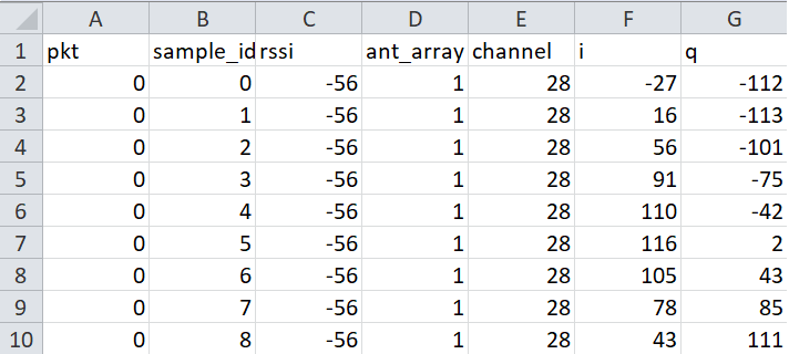
Here we are only interested in the payload part of the AOA_MODE_RAW command. The AoA_MODE_RAW payload has the following structure. In the python script provided above, we have extracted most of the information and save them to a csv file.
  struct = Struct(
      "rssi" / Int8sl,
      "antenna" / Int8ul,
      "channel" / Int8ul,
      "offset" / Int16ul,
      "samplesLength" / Int16ul,
      "samples" / GreedyRange(Struct(
          "q" / Int16sl,
          "i" / Int16sl,
      )),
  )
import matplotlib.pyplot as plt
import pandas as pd
import math
def cal_magnitude(q_value,i_value):
return math.sqrt(math.pow(q_value,2)+math.pow(i_value,2))
def cal_phase(q_value,i_value):
return math.degrees(math.atan2(q_value,i_value))
if __name__ == "__main__":
df = pd.read_csv('sla_rtls_raw_IQ_toggles.csv')
df['phase'] = df.apply(lambda row: cal_phase(row['q'], row['i']), axis=1)
df['magnitude'] = df.apply(lambda row: cal_magnitude(row['q'], row['i']), axis=1)
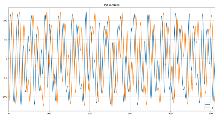
# Plot all the I/Q collected. Each channel will have a plot which contains I/Q samples.
# If you have collected I/Q data on 37 data channels, then there will be 37 windows popped up
grouped = df.groupby('channel')
axes = grouped[['i', 'q']].plot(title="I/Q samples", grid=True)
# Create 4 plots and each plot has x number of subplots. x = number of channels
indexed = df.set_index(['channel', 'sample_idx'])
indexed.unstack(level=0)[['phase']].plot(subplots=True, title="Phase information", xlim=[0,512], ylim=[-190,+190])
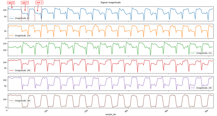
indexed.unstack(level=0)[['magnitude']].plot(subplots=True, title="Signal magnitude", xlim=[0,512])
indexed.unstack(level=0)[['i']].plot(subplots=True, title="I samples", xlim=[0,512])
indexed.unstack(level=0)[['q']].plot(subplots=True, title="Q samples", xlim=[0,512])
plt.show()
This script can be executed as is.
After executing the small script provided above, if the angle between rtls_passive
rtls_slave is not 0 degree, you can see that magnitude of the sine wave is not the same
when you swap betwen antenna 1 and antenna 2 as shown below.
Another alternative to observe the magnitude of received signal is to calculate it based on I/Q data. Since each I/Q pair is a vector, the magnitude of a vector can be calculated by sqrt(I^2+Q^2).
Using the script provided above, you will see a plot called Signal magnitude. In this plot, you can clear see that received signal magnitude from antenna 2 is almost double as from antenna 1.
More information!
If there is no antenna toggling, then the I/Q samples will form a perfect sine wave. To prove it, change the antenna toggling pattern from 2 antennas to 1 antenna(A1.2), and see how the I/Q plots look like.
AoA_Pattern antennaPattern_A1 = {
    .numPatterns = 32,
    .initialPattern = AOA_A1_SEL | AOA_Ax_ANT2,
    .toggles =
    {
     AOA_A1_SEL | AOA_Ax_ANT2, // A1.2
     AOA_A1_SEL | AOA_Ax_ANT2, // A1.2
     AOA_A1_SEL | AOA_Ax_ANT2, // A1.2
     AOA_A1_SEL | AOA_Ax_ANT2, // A1.2
     AOA_A1_SEL | AOA_Ax_ANT2, // A1.2
     AOA_A1_SEL | AOA_Ax_ANT2, // A1.2

     AOA_A1_SEL | AOA_Ax_ANT2, // A1.2
     AOA_A1_SEL | AOA_Ax_ANT2, // A1.2
     AOA_A1_SEL | AOA_Ax_ANT2, // A1.2
     AOA_A1_SEL | AOA_Ax_ANT2, // A1.2
     AOA_A1_SEL | AOA_Ax_ANT2, // A1.2
     AOA_A1_SEL | AOA_Ax_ANT2, // A1.2

     AOA_A1_SEL | AOA_Ax_ANT2, // A1.2
     AOA_A1_SEL | AOA_Ax_ANT2, // A1.2
     AOA_A1_SEL | AOA_Ax_ANT2, // A1.2
     AOA_A1_SEL | AOA_Ax_ANT2, // A1.2
     AOA_A1_SEL | AOA_Ax_ANT2, // A1.2
     AOA_A1_SEL | AOA_Ax_ANT2, // A1.2

     AOA_A1_SEL | AOA_Ax_ANT2, // A1.2
     AOA_A1_SEL | AOA_Ax_ANT2, // A1.2
     AOA_A1_SEL | AOA_Ax_ANT2, // A1.2
     AOA_A1_SEL | AOA_Ax_ANT2, // A1.2
     AOA_A1_SEL | AOA_Ax_ANT2, // A1.2
     AOA_A1_SEL | AOA_Ax_ANT2, // A1.2

     AOA_A1_SEL | AOA_Ax_ANT2, // A1.2
     AOA_A1_SEL | AOA_Ax_ANT2, // A1.2
     AOA_A1_SEL | AOA_Ax_ANT2, // A1.2
     AOA_A1_SEL | AOA_Ax_ANT2, // A1.2
     AOA_A1_SEL | AOA_Ax_ANT2, // A1.2
     AOA_A1_SEL | AOA_Ax_ANT2, // A1.2

     AOA_A1_SEL | AOA_Ax_ANT2, // A1.2
     AOA_A1_SEL | AOA_Ax_ANT2, // A1.2
    }
};
Task 5 – Antenna Switch Settling Time
Now that we are equipped with all the needed tools to manipulate I/Q data, we will try to identify when the antenna is toggling in order to help determine which I/Q samples can be used.
As mentioned in Calculate the phase difference among the antennas, I/Q samples can be presented with constellation diagram, each I/Q pair is a vector and its angle is within a range of +180 ~ -180. Therefore when we have an I/Q pair, to obtain the angle information, we can use arctan to get angle of a vector. Then based on the I and Q value, we can find out the corresponding angle.
| I > 0 | I < 0 | |
|---|---|---|
| Q >=0 | angle = arctan(Q/I) | angle = 180 + arctan(Q/I) |
| Q < 0 | angle = arctan(Q/I) | angle = -180 + arctan(Q/I) |
Luckily in python, the math.atan2 function takes care of the aforementioned logic.
Let's take a look at the Phase Information plot.
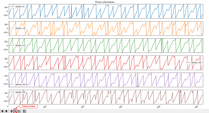
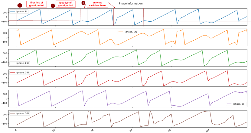
A perfect sine wave, assuming it starts at 0 degree, the phase will first go towards +180 and then, once it crosses +180, it will start from -180 and then go back to 0 degrees. From the picture provided below, you can see that in the first 8us(32 samples), there is no abrupt phase change.
When the rf switches and the angle of incident wave is not 0 degree, you will see abrupt phase change. As shown below after 2 periods, we started to switch antennas. Then the phase we obtained is no long linear.
Hence by looking at the phase information plot, you will know how many I/Q samples you can keep per period.
import queue
import time
import csv
from collections import namedtuple

from rtls.rtlsmanager import RTLSManager
from rtls.rtlsnode import RTLSNode, Subscriber


# Uncomment the below to get raw serial transaction logs

# logging.basicConfig(stream=sys.stdout, level=logging.DEBUG,
#                     format='[%(asctime)s] {%(filename)s:%(lineno)d} %(levelname)s - %(message)s')


if __name__ == '__main__':
    # Initialize, but don't start RTLS Nodes to give to the RTLSManager
    my_nodes = [RTLSNode('COM108', 115200), RTLSNode('COM80', 115200)]

    # prepare csv file to save data
    filename = 'sla_rtls_raw_IQ_toggles.csv'
    outfile = open(filename, 'w', newline='')

    csv_fieldnames = ['pkt', 'sample_idx', 'rssi', 'ant_array', 'channel', 'i', 'q']
    csv_writer = csv.DictWriter(outfile, fieldnames=csv_fieldnames)
    SampleRow = namedtuple('CsvRow', csv_fieldnames)
    dump_rows = []

    csv_writer.writeheader()

    # Initialize references to the connected devices
    masterNode = None
    address = None
    addressType = None
    passiveNodes = []
    slave_addr = '54:6C:0E:A0:4B:B2'  # Slave addr should be set here or set to 'None'
    pkt_limit = 5  # Or None

    # Running packet counter
    pkt_cnt = 0

    # Initialize manager reference, because on Exception we need to stop the manager to stop all the threads.
    manager = None
    try:
        # Start an RTLSManager instance without WebSocket server enabled
        manager = RTLSManager(my_nodes, wssport=None)
        # Create a subscriber object for RTLSManager messages
        managerSub = Subscriber(queue=queue.PriorityQueue(), interest=None, transient=False, eventloop=None)
        # Attach subscriber to manager
        manager.add_subscriber(managerSub)
        # Start RTLS Node threads, Serial threads, and manager thread
        manager.start()

        # Wait until nodes have responded to automatic identify command, and assign nodes to application references
        timeout = time.time() + 5
        while time.time() < timeout:
            if all([node.identifier is not None for node in manager.nodes]):
                try:
                    masterNode = next((n for n in manager.nodes if n.capabilities.get('RTLS_MASTER', False)))
                except StopIteration:
                    pass
                passiveNodes = [n for n in manager.nodes if not n.capabilities.get('RTLS_MASTER', False)]
                break
            time.sleep(0.1)

        # Exit if no master node exists
        if not masterNode:
            raise RuntimeError("No RTLS Master node connected")

        #
        # At this point the connected devices are initialized and ready
        #

        # Display list of connected devices
        print(f"{masterNode.identifier} {', '.join([str(c) for c, e in masterNode.capabilities.items() if e])}")
        for pn in passiveNodes:
            print(f"{pn.identifier} {', '.join([str(c) for c, e in pn.capabilities.items() if e])}")

        print("\nSending example command RTLS_CMD_IDENTIFY; responses below\n")

        # Send an example command to each of them, from commands listed at the bottom of rtls/ss_rtls.py
        for n in passiveNodes + [masterNode]:
            n.rtls.identify()

        while True:
            # Get messages from manager
            try:
                node_msg = managerSub.pend(True, 0.5)
                from_node = node_msg.identifier
                msg = node_msg.message.item
                print(node_msg.as_json())

                # After example identify is received, we start scanning
                if msg.command == 'RTLS_CMD_IDENTIFY':
                    masterNode.rtls.scan()

                # Once we start scanning, we will save the address of the
                # last scan response
                if msg.command == 'RTLS_CMD_SCAN' and msg.type == 'AsyncReq':
                    address = msg.payload.addr
                    addressType = msg.payload.addrType

                # Once the scan has stopped and we have a valid address, then connect
                if msg.command == 'RTLS_CMD_SCAN_STOP':
                    if address is not None and addressType is not None and (slave_addr is None or slave_addr == address):
                        masterNode.rtls.connect(addressType, address)
                    else:
                        # If we didn't find the device, keep scanning.
                        masterNode.rtls.scan()

                # Forwarding the connection parameters to the passives
                if msg.command == 'RTLS_CMD_CONN_PARAMS' and msg.type == 'AsyncReq' and msg.payload.accessAddress is not 0:
                    if node_msg.identifier == masterNode.identifier:
                        for node in passiveNodes:
                            node.rtls.set_ble_conn_info(msg.payload.accessAddress, msg.payload.connInterval,
                                                        msg.payload.hopValue, msg.payload.mSCA, msg.payload.currChan,
                                                        msg.payload.chanMap)

                # Once we are connected and slave setup is completed, we can enable AoA
                if msg.command == 'RTLS_CMD_CONNECT' and msg.type == 'AsyncReq':
                    if msg.payload.status == 'RTLS_SUCCESS':
                        if node_msg.identifier == masterNode.identifier:
                            masterNode.rtls.aoa_set_params('AOA_MASTER', 'AOA_MODE_RAW', 4, 4, 20)
                            masterNode.rtls.aoa_start(1)
                        else:
                            # Iterate over all passive nodes, send ToF params
                            for node in passiveNodes:
                                node.rtls.aoa_set_params('AOA_PASSIVE', 'AOA_MODE_RAW', 4, 4, 20)
                                node.rtls.aoa_start(1)
                    else:
                        # The connection failed, keep scanning.
                        masterNode.rtls.scan()

                # Saving I/Q samples into csv file
                if msg.command == 'RTLS_CMD_AOA_RESULT_RAW':
                    payload = msg.payload
                    # Extract first sample index in this payload
                    offset = payload.offset

                    # If we have data, and offset is 0, we are done with one dump
                    if offset == 0 and len(dump_rows):
                        pkt_cnt += 1

                        # Make sure the samples are in order
                        dump_rows = sorted(dump_rows, key=lambda s: s.sample_idx)

                        # Write to file
                        for sample_row in dump_rows:
                            csv_writer.writerow(sample_row._asdict())

                        # Reset payload storage
                        dump_rows = []

                        # Stop script now if there was a limit configured
                        if pkt_limit is not None and pkt_cnt > pkt_limit:
                            break

                    # Save samples for writing when dump is complete
                    for sub_idx, sample in enumerate(payload.samples):
                        sample = SampleRow(pkt=pkt_cnt, sample_idx=offset + sub_idx, rssi=payload.rssi, ant_array=payload.antenna, channel=payload.channel, i=sample.i, q=sample.q)
                        dump_rows.append(sample)

            except queue.Empty:
                pass

    finally:
        outfile.flush()
        outfile.close()

        if manager:
            manager.stop()
This work is licensed under a Creative Commons Attribution-NonCommercial-NoDerivatives 4.0 International License.