Introduction
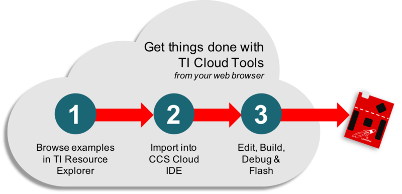
This workshop is a simple introduction for using TI Drivers within the Simplelink™ SDK. The goal for this project is to get you familiarized with your TI LaunchPad™ development kit, introduce you to TI Resource Explorer and the content delivered within, as well as create & compile a simple code example using CCS Cloud.
To get our feet wet, we are going to start basic & will learn how to blink an LED on our LaunchPad using the SimpleLink SDK. Specifically, we are going to be using "TI Drivers", a collection of easy-to-use APIs that provide abstracted, functional access to various peripherals. Note that TI Drivers are compatible across the entire portfolio SimpleLink MCU devices. To do so, we'll start with a code example...
Here's what we'll learn:
- Navigating TI Resource Explorer
- Getting familiar with the SimpleLink SDK & TI Drivers
- Importing projects into CCS Cloud
Editing, building & flashing a TI LaunchPad using the browser-based IDE
Prerequisites
Software for desktop development
This tutorial can be done 100% with a web browser in the cloud. However, the exercises can also be completed using desktop/offline tools as well. If you want to run the exercises offline, you will need to download & install the following:
- CCS 7.1+
- SimpleLink SDK for your given LaunchPad
Hardware requirements
- A SimpleLink LaunchPad Development Kit
Recommended Reading
- SimpleLink SDK Quick Start Guide
- SimpleLink SDK User Guide
Task 1 - Finding the Blink LED code example
1. Finding code examples using TI Resource Explorer
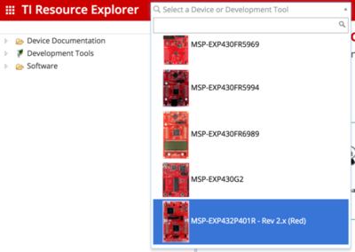
TI Resource Explorer has the ability to filter all of the development resources for a given context. In this case, we can filter & expose all content that is related to this specific LaunchPad. To do so, we can search for the LaunchPad using the search bar on the top-left corner. Clicking on a device or development kit will filter the content presented in TI Resource Explorer.
Once filtered, developers can browse the available resources provided in TI Resource Explorer, which is broken up into 3 categories: Software, Device Documentation & Development Tools. Also, while TI Resource Explorer is cloud-enabled, any of the delivered content can be downloaded locally onto your machine (i.e. to import code examples into a traditional IDE like Code Composer Studio). Alternatively, we can stay in the cloud & import code examples into TI's cloud-connected CCS Cloud IDE, which is what we'll be using for this example.
2. Look inside the "Software" category in TI Resource Explorer.
Here, you will see all of the SDKs that are available for your device/LaunchPad. In this case, we will be using the SimpleLink™ MSP432™ MCU SDK, so expand that folder to find documentation & code examples that are available within the SDK. You can learn more about the SimpleLink MSP432 SDK here, but for now, we will use one of the TI Drivers code examples.
You can find the code examples that showcase how to use the "TI Drivers" at
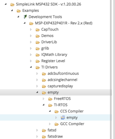
Software > [SimpleLink SDK] > Examples > Development Tools > [LaunchPad] > TI Drivers > [Examples]

3. Expand the "TI Drivers" folder to find many examples on how to exercise various TI Drivers.
TI Drivers is a set of common, consistent functional APIs that are supported across the TI SimpleLink portfolio, enabling maximum code portability.
Few things of note. TI Drivers today require an RTOS. All devices in the SimpleLink platform have support for TI-RTOS. Most SimpleLink devices also support FreeRTOS. However, rather than make direct calls to kernel-specific API calls, the TI Driver code examples leverage POSIX & a Driver Porting Layer (DPL) to provide a consistent API layer on top of a desired kernel. The SimpleLink SDK is compliant with POSIX, an industry standard abstraction layer, which exposes common kernel-related functions through a common set of APIs.
4. Let's look at the "empty" example.
The "empty" project is a template file that builds a framework for a new SimpleLink SDK-based project. In short, it creates a single-threaded application using POSIX APIs that toggles an LED pin high & low using TI Driver APIs. Note that there are several versions of each TI Driver example. An example is available based on TI-RTOS (and FreeRTOS for most SimpleLink devices). Additionally, there are variants that use either the CCS or GCC compiler. Select any version you like. In the screenshot below, we are going to use the TI-RTOS variant that uses the CCS compiler.
Software > [SimpleLink SDK] > Examples > Development Tools > [LaunchPad] > TI Drivers > Examples > empty
Our TI Driver examples use POSIX
POSIX is an abstraction layer that offers source code compatibility between different RTOS Kernels, so regardless of which RTOS variant you select for this example, the application source code is identical & fully portable between TI-RTOS or FreeRTOS.
Additionally, note that each code example is packaged with a readme.html page, which includes helpful documentation offering an overview of each example. A Board.html page is also provided to show how some hardware resources can be accessed in your software (i.e. on-board LEDs, pushbuttons, etc.).
Lastly, without having to download or unzip anything, developers can easily explore the contents of the project. To see the code example source, click on the file within the project & the source will be presented within TI Resource Explorer. The main application for this project is "empty.c"
Task 2 - Importing code example into IDE
1. Import into CCS Cloud IDE
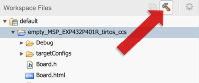
Now that we've identified our code example, we will go ahead and import it into CCS Cloud. We can do so by clicking on the cloud icon when the project folder is highlighted (shown in screenshot below). Clicking this will import the entire project into CCS Cloud, our cloud-based IDE. From there, we will have the ability to edit, compile, flash & even debug our code.
Note that developers also have the option to download this code example & its dependencies locally, which allows you to import these examples into a traditional offline IDE like CCS & IAR. However, for this quick tutorial, we'll stick with the cloud.
If using CCS Cloud, you may be asked to download & install browser extensions.
Chrome is the recommended browser for developing with CCS Cloud.
TI Resource Explorer is also packaged within the traditional desktop version of Code Composer Studio v7
Within the IDE, users will be able to navigate TI Resource Explorer & make the content available for offline consumption by downloading relevant content locally. Once downloaded locally, users can import projects into the IDE with a single click to start development.
Note that the RTOS library project is also imported.
2. Getting familiarized with CCS Cloud
If you haven't already, click the cloud icon to import the "empty" example into CCS Cloud. The example we found has now been imported into CCS Cloud. At this point, we have the ability to edit the code, compile/debug & more. This particular code example shows us how to use the GPIO TI Driver APIs to toggle an I/O pin high & low to blink an LED. You can learn more about this particular code example by again clicking on the Readme.html page that is provided with each example.
The CCS Cloud IDE offers a powerful development environment capable of running in a web browser (Chrome recommended). Within this tool, users can modify their code example, build their project & even debug.
CCS Cloud code editor offers lots of nifty features, including:
- Code folding
- F3 to jump to definition
- Code auto-completion
- Integrated serial monitor/terminal
- More!
CCS Cloud also offers debug capabilities
- Watch variables (and graph them too!)
- Set breakpoints
- Step through code line-by-line
More!
3. Familiarizing ourselves with TI Drivers resources & documentation
Explore these files to get a quick introduction to this code example. Each example is packaged with one.
Board.html
This file provides a high-level visual aid for your board file & shows how you may address different resources available on your LaunchPad kit (LEDs, switches, I/O pins, etc.).
README.html
This file provides an overview for each example.
4. Taking a closer look at the source files
Let's take a look at the empty.c source file - simply double-click the file to open it up in CCS Cloud. In general, this "empty" project provides you with a framework that you can use as a starting point for your own project. It shows you where to include the header files for the TI Drivers you want to use (only the GPIO driver is used in this example). It also provides a framework for your main loop, which is running inside of a single thread called "mainThread."
Inside of mainThread, we see that we have to initialize the GPIO driver before we can use it by calling the GPIO_init() function. Once the driver has been initialized, we can use the driver to set the GPIO high using the GPIO_write() API. We also notice that we are using the Board_PIN_LED0 designator, which was declared in our Board.h file (and is documented in the Board.html file).
Further down mainThead, we see our while(1) loop, which is our main loop for this simple example. Within this loop, we use another GPIO Driver API to toggle the pin. We do this once every second, which is determined by the sleep() function, which takes a parameter for number of seconds. The sleep() function is provided by the unistd.h header that is included in the "empty" project by default.
Another file to take a look at is "main_tirtos.c" or "main_freertos.c" - each example includes one of these files depending on the underlying kernel being used. However, since we are using POSIX in our TI Driver examples, these files are largely identical. Within this file, we configure the kernel, create & configure our thread(s) and set their priorities. For instance, we see that we use the POSIX API pthread_create() to create our mainThread, which is what we saw in our main empty.c source file.
Quick Quiz:
Which API did we use to toggle the LED?
Which file gives you an overview of the code example you're using?
Task 3 - Build your project
1. Build/compile your source code
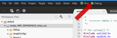
To build your project, simply click the hammer icon. This will compile your code in the cloud & provide a .out file, which you can flash into your device. Alternatively, you can click on the Debug icon, which will compile your code & flash your hardware. It will also jump you into a debug session, where you can step through your code, set breakpoints & watch variables.
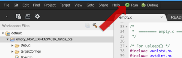
2. Let's load our LaunchPad!
To program our LaunchPad, we can click on the "Run" button in CCS Cloud. This will build our project & flash our hardware with the newly compiled image. This will take a minute or so. Once programmed, your LaunchPad will automatically start to execute the code & the LaunchPad's LED should start blinking!
CHALLENGE: Try to toggle the I/O pin tied to a different LED (if available on your LaunchPad)
Now that we have our LED blinking, use the Board.html file as a resource to modify the project to blink a different LED. Also, be sure to check out the Board.h file to see how these pins are declared.
Task 4 - Add ADC read
1. Introducing the TI Drivers API Guide
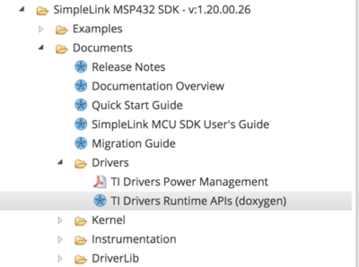
The TI Driver APIs are fully documented within a doxygen-generated API Guide. The API Guide is available in TI Resource Explorer & is delivered within the SimpeLink SDK. You can find the TI Drivers API Guide here:
If using TI Resource Explorer:
[SimpleLink SDK] > Documents > Drivers > TI Drivers Runtime APIs (doxygen)
If browsing the downloaded product in your file system:
<SimpleLink SDK>\docs\tidrivers\tidriversAPIs.html
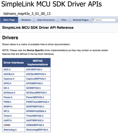
For each TI Driver, you will find a generic usage example, as well as instructions on how to configure & initialize the driver. All functions available for each TI Driver are fully documented to help you exercise the capabilities exposed by the driver.
For example, we can see the API Guide for the GPIO TI Driver that we are leveraging to blink the LED in the "empty" code example used above.
2. Let's modify the example so LED is ON only if an ADC reading exceeds a threshold
For this section, we will use the ADC TI Driver to take an ADC sample periodically. If the ADC reading is greater than a threshold, we will turn the LED on, else we leave it off. To learn how to do this, we can use the TI Driver code examples while looking at the TI Driver API guides.
Let's look at the TI Drivers at [SimpleLink SDK] > Documentation > tidrivers > tidriversAPI.html
Click on ADC.h to see the API guide for the ADC TI Driver.
3. Using TI Drivers: Init, Open, Use, Close.
The TI Driver API Guides show how to initialize, open, use & close each of the TI Drivers. In this case, we want to learn about how to use the ADC driver.
First off, we see that we need to include the ADC driver header file.
Secondly, we see that we have to create a handle for our ADC driver. Once a handle has been created, we have to initialize, then open the driver for use.
Once initialized & opened, the driver can be used. In this simple example, we use the
ADC_convert()API.For our simple example, that's all we need. However, for full details on the ADC driver, you can scroll down the API guide to learn more about the various functions that are exposed by the driver.
4. Adding a simple ADC conversion to our "empty" project
Let's copy & paste the include header code to include the ADC driver into the top of our empty.c example:
#include <ti/drivers/ADC.h>ADC Driver header.
Now that we have the driver added to our project, let's be sure to call ADC_init() to initialize the ADC driver. The "empty" project recommends where to place these driver initializations.
Next, let's create an ADC handle (we can name it whatever we want, but let's stick to "adc"). Let's also initialize & open the driver so we can use it. We can add this code inside of mainThread, right before the while(1) loop (line 72 in the code).
We have to make a small change to the code snippet provided by the API guide. We need to change the ADC pin passed into the ADC_open() API to ensure we are using an available ADC channel. We can again refer to the Board.html resource, or take a look directly at the Board.h file included in the empty project example. Referring to the Board.h file, we see that "Board_ADC0" is available.
/* Open ADC Driver */ ADC_Handle adc; ADC_Params params; ADC_Params_init(¶ms); adc = ADC_open(Board_ADC0, ¶ms); if (adc == NULL) { // Error initializing ADC channel 0 while (1); }ADC handle.
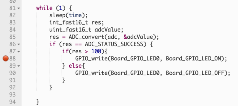
Finally, let's add the ADC conversion code inside of the
while(1)loop to periodically sample the ADC every second. Let's also use a simple if-statement to set the LED high when the ADC result is >= an arbitrary threshold of 100, but off when < threshold. We'll use the GPIO_write() API we learned about earlier in the simple blink "empty" example. Let's also remove the GPIO_toggle() from the original empty example.while (1) { int_fast16_t res; uint16_t adcValue; res = ADC_convert(adc, &adcValue); if (res == ADC_STATUS_SUCCESS) { if(adcValue >= 100){ // arbitrary threshold GPIO_write(Board_GPIO_LED0, Board_GPIO_LED_ON); } else{ GPIO_write(Board_GPIO_LED0, Board_GPIO_LED_OFF); } } sleep(time); }ADC_convert() with simple LED toggle if-statement.
Task 5 - Add UART print
1. Adding a serial UART transmission to report ADC readings
A Display Driver is available, which offers a consistent API set for displaying data across multiple mediums (Serial UART, LCD, etc.). In this case, we will use the Display API to send our ADC readings back to a terminal window.
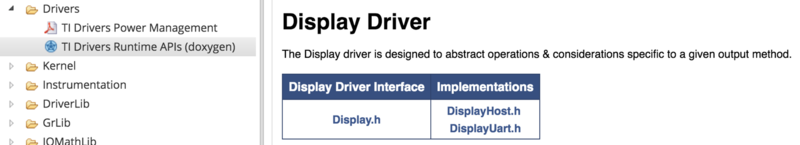
We can learn more about the Display Driver within the TI Driver API Guide. Click on Display.h to learn about how to use the driver to send data over a serial UART.
Add the required header file to the top of our empty.c source file:
#include <ti/display/Display.h>Display Driver header.
Just like the ADC driver, we see that we need to include the appropriate header file. We also see that we need to initialize & open the driver before we can use it.
Next, we need to create a handle for our Display driver, and need to initialize & open the driver. Note that we need to use the "Display_Type_UART" parameter when we open the Display driver to use it for serial communication.
Display_Handle    displayHandle;
Display_Params    displayParams;

Display_Params_init(&displayParams);
displayHandle = Display_open(Display_Type_UART, NULL);
Display handle.
Ultimately, we can use the driver & close it when we no longer need it.
We can now use the Display_printf() API to send data over serial UART. Let's send our ADC readings after every ADC conversion.
Display_printf(displayHandle, 1, 0, "ADC Reading %d", adcValue);Display_printf() API.
2. Here's the code you should end up with...
/*
* ======== empty.c ========
*/
/* For usleep() */
#include <unistd.h>
#include <stdint.h>
#include <stddef.h>
/* Driver Header files */
#include <ti/drivers/GPIO.h>
#include <ti/drivers/ADC.h>
#include <ti/display/Display.h>
// #include <ti/drivers/I2C.h>
// #include <ti/drivers/SDSPI.h>
// #include <ti/drivers/SPI.h>
// #include <ti/drivers/UART.h>
// #include <ti/drivers/Watchdog.h>
/* Board Header file */
#include "Board.h"
/* global variableS FOR GUI COMPOSER */
uint16_t adcValue = 0;
uint16_t threshold = 100;
uint16_t trigger = 0;
/*
* ======== mainThread ========
*/
void *mainThread(void *arg0)
{
/* ~10 loops/second */
uint32_t time = 100000; // update ~10/second
/* Call driver init functions */
GPIO_init();
ADC_init();
// I2C_init();
// SDSPI_init();
// SPI_init();
// UART_init();
// Watchdog_init();
/* Open Display Driver */
Display_Handle displayHandle;
Display_Params displayParams;
Display_Params_init(&displayParams);
displayHandle = Display_open(Display_Type_UART, NULL);
/* Open ADC Driver */
ADC_Handle adc;
ADC_Params params;
ADC_Params_init(¶ms);
adc = ADC_open(Board_ADC0, ¶ms);
if (adc == NULL) {
// Error initializing ADC channel 0
while (1);
}
while (1) {
int_fast16_t res;
res = ADC_convert(adc, &adcValue);
if (res == ADC_STATUS_SUCCESS) {
Display_printf(displayHandle, 1, 0, "ADC Reading %d", adcValue);
if(adcValue >= threshold){
GPIO_write(Board_GPIO_LED0, Board_GPIO_LED_ON);
trigger = 1;
} else{
GPIO_write(Board_GPIO_LED0, Board_GPIO_LED_OFF);
trigger = 0;
}
}
usleep(time);
}
}
Code example after all of our modifications.
3. Program your LaunchPad (and simple debugging)!
Go ahead and click on the "debug" icon in CCS Cloud to jump into a debug session. We will use some of the basic debug capabilities provided by this browser-based IDE, namely breakpoints & watching variables.
Once in your debug session, we will create 2 breakpoints. Click the margin next to the line of code that is inside of the if-statement when the ADC reading is >= to our arbitrary threshold of 100. This will create a breakpoint. Let's also create a breakpoint for when our ADC readings are < the threshold. Notice that the new breakpoint we added now appears in our "Breakpoints" window within the IDE.
We also want to use a "watch window" see the latest and greatest ADC readings. To do so, right-click on the variable name that you want to watch - in this case "adcValue." A context window will pop up - click on "Add Watch Expression." Doing so will add this variable to the "Variables" window.
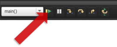
Click on the "Resume" button to start executed your code, or press F8 on your keyboard!
Use an analog sensor (potentiometer) or a simple wire & tie it to VCC or GND to alter the ADC readings. Notice that we hit the breakpoints & we are able to see the ADC results in our variable watch window. Nice!
Check your Board.h file
Remember to check your board file to check which pin your ADC0 is connected to.
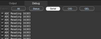
4. Using CCS Cloud's built-in Serial Monitor/Terminal.
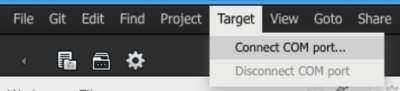
You can open up a terminal by going to: Target > Connect COM Port
Select the COM port your LaunchPad is connected to. The Display Driver defaults to 115200 Baud.
To see your incoming UART messages, take a look at the Debug tab & enable the "Serial" filter to see your messages.
Great! Now what?
Now that you're a bit more familiar with TI Resource Explorer, have some exposure with the SimpleLink SDK & have successfully built & downloaded a project to your LaunchPad using CCS Cloud, we recommend you start exploring the rest of the SimpleLink SDK.
A good place to start is the SimpleLink SDK "Documentation Overview". Here you will find documentation on the SDK & its contents. Happy coding!
SimpleLink MSP432 SDK Documentation Overview is available here: [SimpleLink SDK] > Documents > Documentation Overview
This work is licensed under a Creative Commons Attribution-NonCommercial-NoDerivatives 4.0 International License.