Introduction
The SimpleLink SDK TI 15.4-Stack Plugin allows the use of the TI 15.4 communication stack (running on the SimpleLink CC1310 Sub-1GHz device) with SimpleLink MCU platforms such as MSP432P4, MSP432E4 and CC3220SF.
The TI 15.4-Stack that is running on SimpleLink CC1310 is a IEEE 802.15.4e/g-based star topology networking solution for Sub-1 GHz ISM bands including: 868 MHz, 915 MHz, and 433 MHz. The TI 15.4-Stack is for TI's SimpleLink MCUs offering advantages such as lower power, longer range operation, and better protection against interferance.
Like any SimpleLink SDK Plugin, TI 15.4-Stack Plugin extends the functionality of individual platform SDKs by adding new features such as the TI 15.4-Stack. It is not meant to be a standalone package and relies heavily on components from the platform SDK like TI-Drivers and RTOS kernel components.
SimpleLink SDK Plugin Resources
- For an in-depth look into the concept of SimpleLink SDK Plugins, please refer to the SimpleLink SDK Plugins Overview SimpleLink Academy module.
- For a full list of plugins, please refer the "SDK Plugins" folder on TI Resource Explorer
In this lab, we will run the following examples:
- Collector -
- This application implements the PAN-Coordinator (Personal Area Network), or the central node in the network. This application runs on the host SimpleLink MCU.
- To enable the CC1310 to communicate with the host MCU (running the collector example), a binary file is provided in the plugin that is based on the coprocessor example in the SimpleLink CC1310 SDK.
- The Collector application starts the network, allows devices to join the network, and configures the joining devices on how often to report the sensor data. It then sends periodic tracking request messages (to which it expects tracking response messages) to determine whether or not the sensor nodes are alive in the network.
- TI 15.4-Stack Gateway -
- This application also implements the PAN-Coordinator like the Collector example.
- In addition, it provides a path for the data received from the joining sensor node (running TI 15.4 Stack) to the cloud where possible.
To enable quick evaluation of the Collector and the TI 15.4-Stack Gateway, a binary file is provided for the Sensor Node that needs to be programmed onto a CC1310 LaunchPad. This binary file is based on the Sensor example in the SimpleLink CC13x0 SDK which implements the networked device to join the network started by the Collector. With this binary, the Sensor periodically sends data reports at the report interval configured by the Collector and responds to the tracking messages it receives.
This lab is split into the following tasks to demonstrate taking data from a sensor node to the cloud and visualizing it.
- Task 1: Programming the CC1310 boards.
- Task 2: Setting up the Collector.
- Task 3: Building and Loading the Collector Example.
- Task 4: Running the Collector Example.
- Task 5: Updating the Sensor's Reporting Rate.
- Task 6: Setting up IBM Cloud Account
- Task 7: Building and Loading the TI 15.4-Stack Gateway Example.
- Task 8: Running the TI 15.4-Stack Gateway Example.
- Task 9: Visualizing the Data.
Device compatibility
- Task 1 through 5 are meant for all MSP432E4, MSP432P4 and CC3220SF devices
- Task 6 through 9 are meant ONLY for MSP432E4 and CC3220SF devices
Prerequisites
Recommended Reading
- Sensor and Collector - TI 15.4-Stack Project Zero
- SimpleLink SDK TI 15.4 Stack Plugin Users Guide
- SimpleLink SDK TI 15.4 Stack Plugin Documentation Overview
- SimpleLink SDK Plugins Overview
Software
- Code Composer Studio v8.2.0 and newer
- SimpleLink SDK TI 15.4 Stack Plugin 2.20.xx and newer
- SDK for platform of choice:
- Uniflash v4.3.1.1835 and later
- Terminal emulator program such as TeraTerm or PuTTY
Hardware
- 2x CC1310 LaunchPads [one as coprocessor and one as a sensor node]
- 1 LaunchPad of choice to act as host MCU:
- MSP432P401R LaunchPad (MSP-EXP432P401R)
- MSP432P4111 LaunchPad (MSP-MSP432P4111)
- MSP432E401Y LaunchPad (MSP-MSP432E401Y)
- CC3220SF LaunchPad (CC3220SF-LAUNCHXL)
- 2x Micro-USB cables (included with LaunchPad/BoosterPack)
CC3220S LaunchPads
Currently, this lab will not work with CC3220S devices.
Task 0: Label your LaunchPads
- Label one LaunchPad as "Sensor" and the other as "Collector". These labels will be referred to throughout this lab. It is recommended to use a non-permanent marking for this (e.g. sticky notes), as these labels may only be relevant for this specific lab.
Task 1: Programming the CC1310 boards
Install the UniFlash utility to program the CC1310 LaunchPads with the provided binary files.
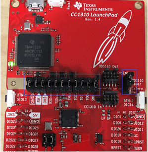
Plug the provided USB cable from your computer into the micro USB port of the CC1310 Launchpad that you labelled as Collector.
Note
Make sure jumpers are in default position as shown in the image below.
Once connected, open up UniFlash and select
LAUNCHXL-CC1310and then click the button Start.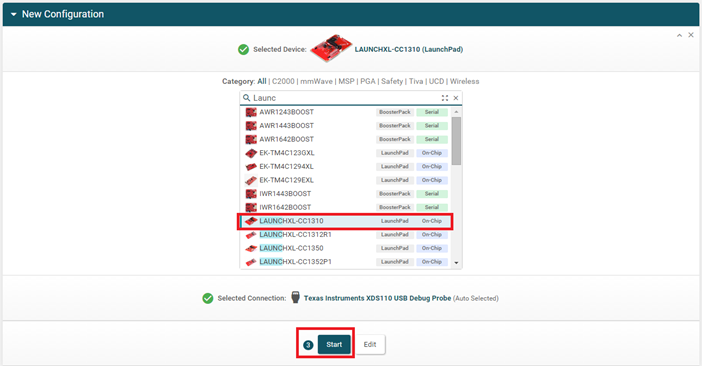
Next, click the Browse button and double-click on the coprocessor firmware, located at the following path in the TI 15.4 Stack plugin's installation folder.
- For MSP432 -
./tools/cc13xx_tools/cc1310_cop_firmware/msp432_coprocessor_cc1310lp.hex - For CC3220 -
./tools/cc13xx_tools/cc1310_cop_firmware/cc3220_coprocessor_cc1310lp.hex
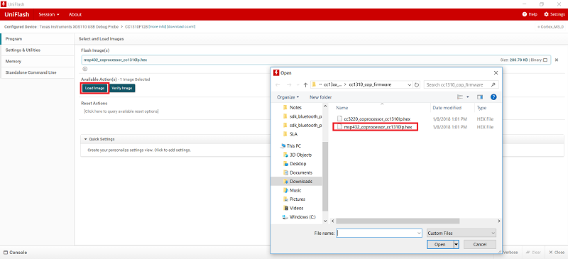
- For MSP432 -
Click on the button Load Image. Once the programming is completed, the CC1310 Launchpad (marked as Collector) is ready to be used as a Sub-1GHz TI 15.4 MAC Coprocessor.
Note:
You might be prompted to update the XDS110 firmware. Follow the prompts to update the firmware. The coprocessor image will be loaded after the XDS110 firmware is updated.
Unplug the CC1310 LaunchPad (marked as Collector) and plug the CC1310 LaunchPad (marked as Sensor).
Follow steps 3 through 5 to now program the sensor firmware that is located at the following path in the TI 15.4 Stack plugin's installation folder. We will use the sensor firmware that was built with Frequency Hoping disabled.
./tools/cc13xx_tools/15_4_sensor_firmware/sensor_cc1310lp_noFH.hexOnce the programming is completed, the CC1310 Launchpad (marked as Sensor) is ready to be used as a Sub-1GHz TI 15.4 Sensor Node.
Task 2: Setting up the Collector
In this task we will set-up the Collector by connecting the CC1310 LaunchPad (marked as Collector) to the host MCU LaunchPad.
Note
From Task 2 onwards, this lab refers to MSP432E4, but these steps are the same with any of the supported platforms unless specified.
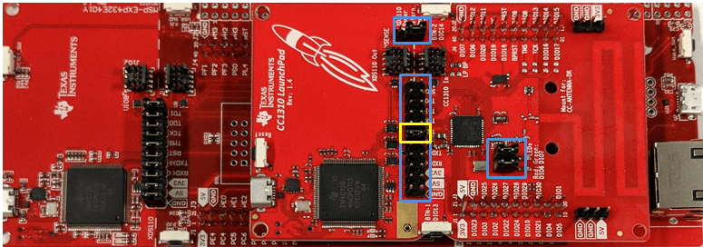
Connect the CC1310 (marked as Collector) to the host MCU. Ensure that the header pins are aligned correctly by checking that the pins marked 3V3, 5V, and GND match. Refer the following image.
Remove all the jumper pins except for the Reset from the header that connects XDS110 to the MCU. Switch the jumper from XDS110 Power (Default) to Extended Power.
Task 3: Building and Loading the Collector Example
Power on the host MCU by plugging the provided USB cable from your computer into the micro USB port of the host MCU LaunchPad.
Import the
collectorexample into CCS Desktop from the following path in the TI 15.4 Stack plugin's installation folder../examples/rtos/[Desired_LaunchPad]/demos/collector/tirtos/ccs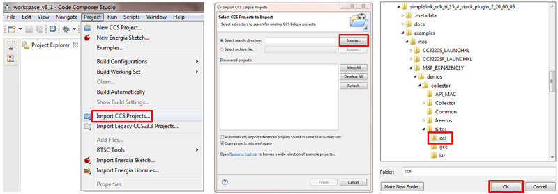
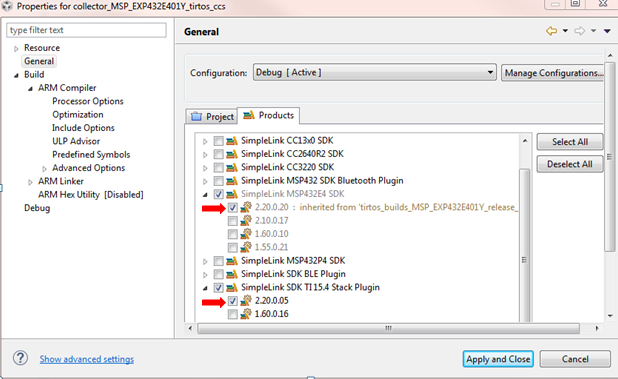
Note
Ensure that the version number for your SimpleLink SDK matches the version number for SimpleLink SDK TI 15.4 Stack Plugin. For more information, check out the CCS Quick Tips.
If you do not want to modify the channel allocation, skip to step 5. Otherwise locate the file
config.hin the Project Explorer, and open it.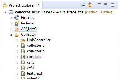
In the
config.h, update the definition ofCONFIG_CHANNEL_MASK.Using the config.h file
Refer to Task 1 of the Sensor and Collector - TI 15.4-Stack Project Zero module for information on:
- Updating the channel allocation
- Selecting the right PHY
Build the example code and program your device.
Build and program the example code by clicking on the green bug icon. This loads the application to the MSP432 and starts a CCS debug session.

Build the example to generate the application binary file. Load the binary file to the external serial flash by using UniFlash ImageCreator.
UniFlash ImageCreator
Refer to the UniFlash ImageCreator Basics module for an introduction and step-by-step tutorial on how to program the external serial flash of SimpleLink Wi-Fi devices.
Task 4: Running the Collector Example
If the the CC1310 LaunchPad (marked as Sensor) has been unplugged from the PC, plug it back in.
Open two instances of the terminal program. Connect one to the collector's (host MCU LaunchPad + CC1310 LaunchPad) and the other to the sensor's (CC1310 LaunchPad) COM port. These ports should have the word "UART" in their names. If you are using a CC3220 device, select the XSD110 Class Application/User UART port.
Configure the serial ports with the following settings:
- Baud rate: 115200
- Data: 8 bit
- Parity: none
- Stop: 1 bit
- Flow control: none
Start the
collectorapplication running on the host MCU. If you are using a MSP432 device, exit the debug session. If you are using a CC3220 device, reset the LaunchPad.Observe and Understand
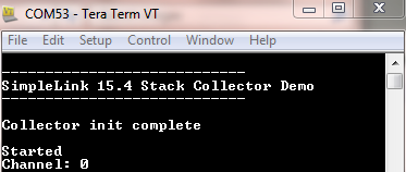
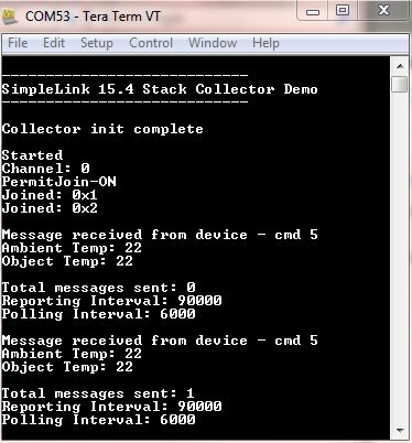
- The collector terminal should look like this:
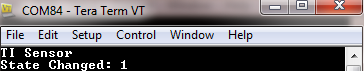
- The sensor terminal like this:
- When the collector terminal says "Started" and "Channel: x", where x will be the number of the actual channel that was selected, the collector has started the network.
- At this point the collector does not allow devices to join the network.
Troubleshooting
If the collector's terminal does not say "Started" and "Channel: x", then reset the CoProcessor (the CC1310 LaunchPad that is connected to the host MCU) and the host MCU.
- The collector terminal should look like this:
Press the
Board_GPIO_BUTTON0on the host MCU's LaunchPad to allow new devices to join the network. The collector's terminal will say "PermitJoin-ON".Board_GPIO_BUTTON0
Refer to the
Board.hfile of the project to see which buttonBoard_GPIO_BUTTON0maps to on the host MCU LaunchPad.Observe and Understand
The sensor will join the network after a short while, indicated by the red LED turning on the sensor. The collector's terminal will say "Joined: 0xX" where 0xX is the sensor ID, and the sensor's terminal will say "Started: 0xX" (0xX is the sensor ID), "Channel: x" and "State Changed 3" indicating successful network connection.
Troubleshooting
If the sensor does not join after a short while, reset the sensor node to Factory New state by pressing and holding Button 2 on the CC1310 LaunchPad, and then pressing the Reset button (while Button 2 is held down).
After a short delay, the sensor reading should display on the collector's terminal window.
Observe and Understand
- Whenever a reading is sent from the sensor, the green LED will toggle on the sensor.
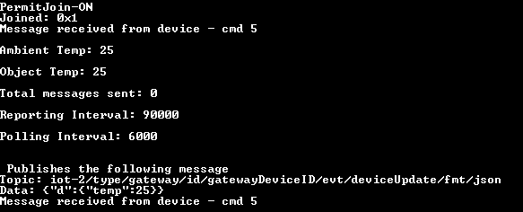
- Once the collector receives data from the sensor, the collector's terminal will say "Message received from device" along with the sensor data.
- The collector's terminal will say "Reporting Interval: x" where x is the reporting interval.
- Readings are sent from the sensor periodically. By default, the collector configures the period to 90 seconds. If the sensor fails to receive the configuration from the collector, it will send the readings every 3 minutes.
- The collector's terminal will say "Polling Interval: x" where x is the polling interval.
- The collector can only send commands to the sensor after the sensor is polling for data. These poll requests are sent by the sensor periodically to allow the sensor to sleep. The default sensor poll rate is 6 seconds. This poll rate can be changed by the collector as part of the configuration message.
Task 5: Updating the Sensor's Reporting Rate (optional)
To get a more responsive demo, the reporting and the polling rates that the collector requests can be updated. The default reporting interval of the sensor also needs to be updated. The SimpleLink CC13x0 SDK is required for this step to update the sensor example firwmare that we programmed as a HEX file to the CC1310 LaunchPad (marked as Sensor) in Task 1.
Download the SimpleLink CC13x0 SDK and import the
sensorexample into CCS.Instructions to use sensor example code
Refer Task 2 of the Sensor and Collector - TI 15.4-Stack Project Zero SimpleLink Academy Module for step by step instructions to Import, Build and Load the
sensorexample.Update the reporting and the polling rate.
Instructions to update the Reporting Rate
Refer Task 4 of the Sensor and Collector - TI 15.4-Stack Project Zero SimpleLink Academy Module for step by step instructions to update the reporting and the polling rate for the
sensorandcollectorprojects.
Task 6: Setting up IBM Cloud Account
Using the collector example, we have seen how to create a TI 15.4 Stack PAN to receive data from sensor nodes. Now let's look at how to take the data from the sensor nodes to the cloud. To do that, we need to set up an IBM Cloud Account.
Set up an IBM Cloud Account and launch an IoT service.
IBM Account Set-up
For detailed instructions, see the Creating an IBM Cloud Account section from the SimpleLink SDK TI 15.4 Stack Plugin's User's Guide and follow step 1 through step 9.
Create a custom Gateway device type. We will use this device type with the
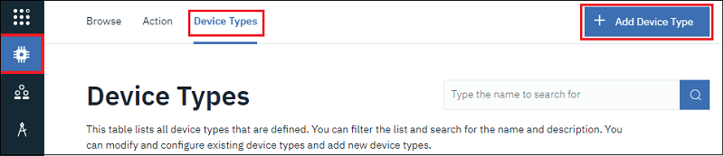
ti_154_gateway_ibmexample which advertises itself as gateway.Select Devices from the navigation bar on the left, and then select Device Types in the top menu. Then click on Add Device Type in the top right.
Under the Identity tab, select Gateway for type of device and enter
gatewayas the name of the device type. Click Next.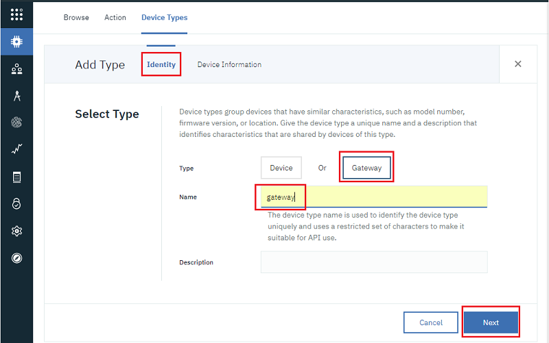
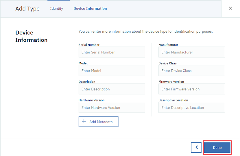
On the Device Information tab, ignore the metadata information and click Next.
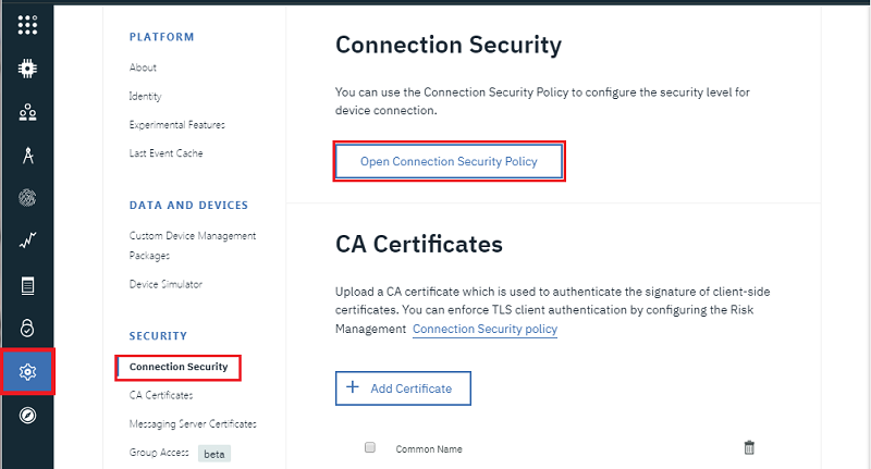
Let's update the connection security policy to make TLS connection optional.
Click on the Settings icon in the left menu. On the resulting page, click on Connection Security option, then click on Open Connection Secuirty Policy button.
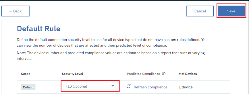
Under Default Rule section, select TLS Optional from the drop-down list under the Security Level for Default Scope. Then click Save.
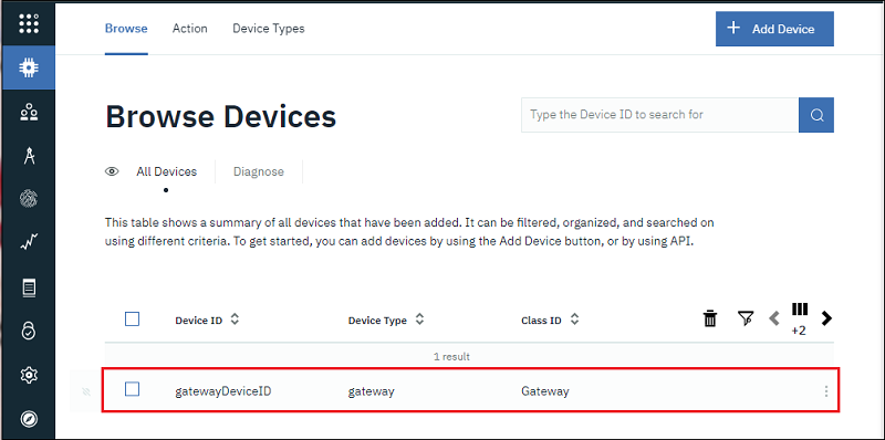
Now add the host MCU device to the IBM cloud by following step 10 through step 14 of the Creating an IBM Cloud Account section in the SimpleLink SDK TI 15.4 Stack Plugin's User's Guide
When the Device has been added, it should look as shown below:
Task 7: Building and Loading the TI 15.4-Stack Gateway Example
Follow steps 1 through 4 in Task 3 to import the
ti_154_gateway_ibmexample and update theconfig.hfile.Note:
ti_154_gateway_ibmexample is supported for the following devices only:- MSP432E4
- CC33220SF
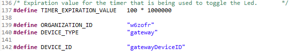
Open
mqtt_client_app.cand update the following lines with your IBM Cloud account information#define ORGANIZATION_ID "abcdef" #define DEVICE_TYPE "gateway" #define DEVICE_ID "gatewayDeviceID"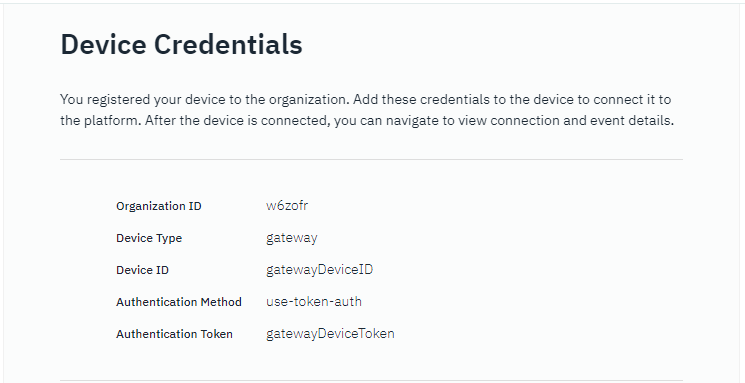

If you are using a CC3220 device, update the following lines in
network_if.hwith the name and security details your Access Point with internet connection./* AP SSID */ #define SSID_NAME "MyRouter" <br> /* Security type (OPEN or WEP or WPA) */ #define SECURITY_TYPE SL_WLAN_SEC_TYPE_WPA_WPA2 <br> /* Password of the secured AP */ #define SECURITY_KEY "MyPassword" <br>Follow steps 5 through 6 in Task 3 to build and program the host MCU.
Task 8: Running the TI 15.4-Stack Gateway Example
If you are using a MSP432E4 device, connect the Ethernet Cable to the LaunchPad. Ensure that the other end is connected to a network that has DHCP server and internet connection.
Setup the terminal windows as before. This is in step 1 through step 3 of Task 4.
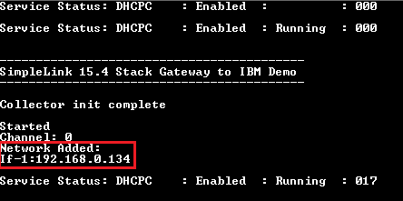
Build the
ti_154_gateway_ibmexample code and program your device as before. This is in step 5 of Task 3.For MSP432E4 device, the gateway terminal should look as below.
Troubleshooting
If the collector's terminal does not display an IP address, check the Ethernet connection and ensure that the network has DHCP server on it.
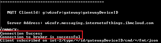
Next, the host MCU will try to connect to the IBM cloud's MQTT broker and report the connection status.
Troubleshooting
If the connection to broker has failed:
- Check if internet connection is available in the network.
- Verify your IBM cloud is set up correctly as described in Task 6
At this point, the sensor has not joined the TI 15.4 Stack network. Refer to step 4 and step 5 of Task 4 to setup the collector so that the sensor node can join the network.
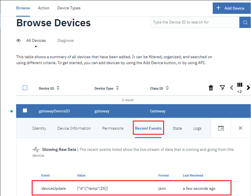
Data received by the gateway from the sensor node is displayed on the gateway's terminal window and sent to the IBM cloud.
To view the data on the IBM cloud, expand the device item and click on Recent Events.
Task 9: Visualizing the Data
The communication between the sensor node and the IBM cloud can be visualized to make it easier to consume this data.
LED toggle
The ti_154_gateway_ibm example demonstrates how to send temperature data to IBM cloud. The example also has support to toggle the red LED on the sensor LaunchPad from the cloud. This can be done by publishing to the topic defined by SUBSCRIPTION_TOPIC0 in mqtt_client_app.c. The default topic is displayed below.
    /* Defining Subscription Topic Values                                         */
    #define SUBSCRIPTION_TOPIC0      "iot-2/type/+/id/%s/cmd/+/fmt/json"
This task demonstrates different ways to visualize the sensor data as well as control the LED sensor node.
One of the ways to visualize data for the
ti_154_gateway_ibmexample is to use the GUI Composer. The GUI Composer's IBM IoT Tutorial has a step by step guide to create a user friendly GUI to view the temperature data.Note:
The GUI Composer's IBM IoT Tutorial uses a CC3200 device, which is not a supported platform for this plugin. The steps to connect your GUI to the cloud will be similar for MSP432E4 or CC3220 devices.
Add a toggle button to your GUI and use the following value to bind the checked property to your cloud as before.
gatewayDeviceID.deviceUpdate.buttonThe following is an example GUI created using the GUI Composer.
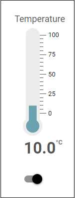
Generate a GUI with IBM tools
You could also use the tools provided by IBM to create a GUI to visualize the temperature data and button toggle. Please refer IBM's getting started tutorial.
References
- MSP432E4 Technical Reference Manual
- CC3220 Technical Reference Manual
- CC13x0 Technical Reference Manual
Technical support
For any questions you might have, please search on the E2E Forum.
This work is licensed under a Creative Commons Attribution-NonCommercial-NoDerivatives 4.0 International License.