Introduction
Welcome to the MSP430 Timer capture academy. This academy introduces the basics of using the Timer_A module in capture mode to calculate the frequency of an external signal and is demonstrated on a MSP-EXP430FR2433 LaunchPad.
Prerequisites
Hardware
The following hardware is required for this lab
- MSP-EXP430FR2433 LaunchPad
- 1 female-to-female Jumper wire
Software
NOTE:
This software examples used for this lab should be imported from within the TI Resource Explorer. This can be accessed from the web or within a locally in CCS by clicking View->Resource Explorer. Prior to Importing a Project, you first need to download MSP430Ware in order to be able to import the examples to the CCS IDE. This may be done when CCS was installed or can be done later by clicking the "Download and Install" icon in the top right. Note that installing MSP430Ware for any project will install ALL labs and content, so this only needs to be done once.
Associated academies
These academies cover using the timer in different modes as well as provide additional information on the timer functionality.
Recommended Resources
The Precision Labs training videos series provides baseline introduction to the timers and clocks.
The documentation can be referenced for the MSP430 MCU and the LaunchPad details.
- TI’s Precision Lab Videos: Clocks and Timing
- MSP430FR2433 MCU Datasheet
- MSP430FR4xx_2xx MCU UserGuide
- MSP-EXP430FR2433 Launchpad User's Guide
- MSP430 MCUs Development Guide Book
Overview
In this lab you will be using the MSP430FR2433's Timer_A module to learn how timer modules work in MSP430 MCUs. There are a few versions of timer modules in MSP430 devices that may have varying features (such as Timer_B), however Timer_A is a very good representation of the MSP430 Timer architecture.
Each timer academy will review example code to show how to initialize necessary I/O pins, clocks, and configure Timer_A for its specified purpose, and include instructions for you to modify the provided example as well as quiz questions to check your understanding.
For introduction to Timer_A features, please see the Timer: Counter Academy Timer: Counter Mode. In this academy we detail the capture features of the Timer_A module.
In this lab, you will be using the MSP430FR2433's Timer_A module to execute a task using the Timer_A capture module to calculate the frequency of an incoming PWM signal.
Timer_A Capture Introduction:
Timer_A is a 16-bit timer/counter with up to seven capture/compare registers (CCRx). Timer_A can support multiple captures or compares, PWM outputs, and interval timing. Timer_A also has extensive interrupt capabilities. Interrupts may be generated from the counter on overflow conditions and from each of the capture/compare registers. More details can be found in the Timer_A Chapter of the MSP430FR4xx_2xx MCU UserGuide.
The 16-bit timer/counter has four operating modes: Up Mode, Continuous Mode, Up/Down Mode and Capture/Compare Mode. In this academy, we focus on the capture mode.
Capture Mode
The capture mode is selected when the control register bit CAP = 1 in the TAxCCTLn Register (Timer_Ax Capture/Compare Control n Register). Capture mode is used to record time events. It can be used for speed computations or time measurements. The capture inputs CCIxA and CCIxB are connected to external pins or internal signals and are selected with the CCIS bits. The CM bits select the capture edge of the input signal as rising, falling, or both. A capture occurs on the selected edge of the input signal. If a capture occurs:
- The timer value is copied into the TAxCCRn register.
- The interrupt flag CCIFG is set.
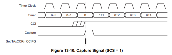
The capture signal can be asynchronous to the timer clock and cause a race condition. Setting the SCS bit synchronizes the capture with the next timer clock and is recommended.
Note: Reading TAxCCRn in Capture mode
In Capture mode, if TAxCCRn is read by the CPU while the timer counter value is being copied into TAxCCRn at a capture event, the value read by the CPU could be invalid. To avoid this undesired result, TAxCCRn must be read after the CCIFG flag is set and before the next capture event occurs.
Note: Changing Capture Input source (CCIS bits)
Switching between CCIxA and CCIxB while in capture mode may cause unintended capture events. To avoid this scenario, capture inputs should only be changed when capture mode is disabled (CM = {0} or CAP = 0).
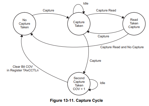
Capture Overflow
Overflow logic is provided in each capture/compare register to indicate if a second capture was performed
before the value from the first capture was read by the CPU, meaning the previous caputure data was lost. The
COV bit is set when this occurs and must be reset with software.
Getting Started
Hardware Setup:
-
- Plug in the MSP430FR2355 Launchpad into your PC using a Micro-USB cable.
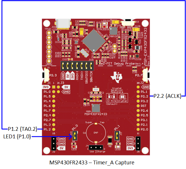
- Connect P1.2 to P2.2 using the jumper wire as shown below.
Hardware Connections
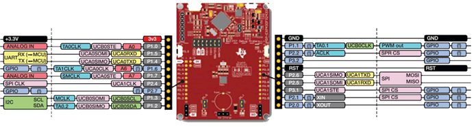
LaunchPad Boosterpack Pinout
Task 1 – Import, program, and edit the Timer_A CCR0 Capture example
Example Project Overview
This demo captures a number of periods of the ACLK clock and store them in an array. When the set number of periods is captured the program is trapped and the LED on P1.0 starts blinking. At this point halt the program execution and read out the values using the debugger in CCS.
ACLK = REFOCLK = 32kHz, MCLK = SMCLK = default DCODIV = 1MHz.
Import the timer example
- Import the Timer0_A3 Capture of ACLK example msp430fr243x-ta0-capture.c
into CCS from TI Resource Explorer.
MSP430ware→Devices→MSP430FR2XX_4XX→MSP430FR2433→Peripheral Examples→Register Level→
msp430fr243x-ta0-capture.c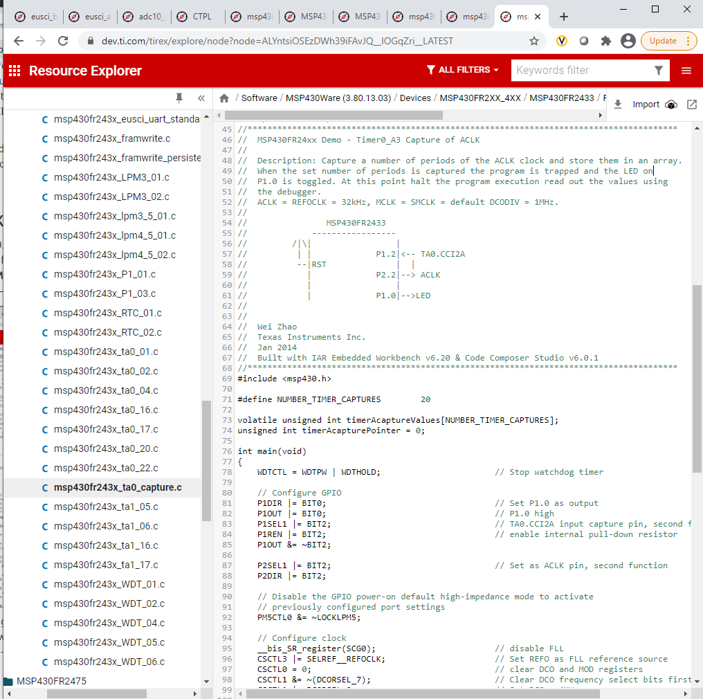
- Click import in the upper right hand corner Using Resource Explorer, navigate to: Software->MSP430Ware-3.8x.xx.xx->Devices->MSP430FR2433->Register Level->
Code Overview
Initialization and GPIO configuration
Before configuring the MSP430's Timer_A module, we need to initialize the the MSP430 by disabling the watchdog timer and initializing the GPIO pin for the LED as an output.
The watchdog timer must be stopped to prevent the MCU from reseting while the demo is running. P1.0 is configured for an output and is connected to a header and LED on the Launchpad.
    WDTCTL = WDTPW | WDTHOLD;                    // Stop watchdog timer

    P1DIR |= BIT0;                               // Set P1.0 as output
    P1OUT |= BIT0;                               // P1.0 high
Now we need to configure the Timer_A Capture pin. The Compare/Capture Input (CCI) pin is a secondary function on certains pins.
According to Table 6-17 of the MSP430FR2433 datasheet, P1.2 can be configured to TA0.CCI2A by setting the P1DIR.x and P1SEL.x to the specified values.
Ensure to enable a pull-down resistor on the capture input pin by enabling the resistor (PxREN = 1) and setting it as a pull-down (PxOUT = 0).
    P1SEL1 |= BIT2;                                 // TA0.CCI2A input capture pin, second function
    P1REN |= BIT2;                                  // enable internal pull-down resistor
    P1OUT &= ~BIT2;
To provide a signal to input to the capture pin, we can use ACLK as the input source by connecting it to a pin on the LaunchPad. Table 6-18 of the datasheet shows that P2.2 has ACLK as a secondary function.
    P2SEL1 |= BIT2;                                 // Set as ACLK pin, second function
    P2DIR |= BIT2;
Finally, to apply the GPIO configurations disable the LOCKLPM5 bit in PM5CTL0.
    // Disable the GPIO power-on default high-impedance mode to activate
    // previously configured port settings
    PM5CTL0 &= ~LOCKLPM5;
Clock configuration
The next order of business is to configure the master and auxiliary clock sources through the Frequency Lock Loop (FLL). The Master clock (MCLK) and Sub-main clock (SMCLK) are configured to 1 MHz from the Digitally Controlled Oscillator (DCO), and the Auxillary Clock is configured to 32.678kHz from the REFOCLK (low-frequency oscillator).
    // Configure clock
    __bis_SR_register(SCG0);                        // disable FLL
    CSCTL3 |= SELREF__REFOCLK;                      // Set REFO as FLL reference source
    CSCTL0 = 0;                                     // clear DCO and MOD registers
    CSCTL1 &= ~(DCORSEL_7);                         // Clear DCO frequency select bits first
    CSCTL1 |= DCORSEL_2;                            // Set DCO = 4MHz
    CSCTL2 = FLLD_1 + 60;                           // DCODIV = 2MHz
    __delay_cycles(3);
    __bic_SR_register(SCG0);                        // enable FLL
    while(CSCTL7 & (FLLUNLOCK0 | FLLUNLOCK1));      // Poll until FLL is locked

    CSCTL4 = SELMS__DCOCLKDIV | SELA__REFOCLK;      // set default REFO(~32768Hz) as ACLK source, ACLK = 32768Hz
                                                    // default DCODIV as MCLK and SMCLK source
    CSCTL5 |= DIVM__1 | DIVS__2;                    // SMCLK = 1MHz, MCLK = 2MHz
Timer configuration
All that is left to do is to initialize the Timer_A module for capture mode.
There are plenty of important parameters that need to be configured in the TAxCCTLn register in order to use capture mode.
Recall, since we are using the Timer A, Instance 0, Compare/Capture Register 2, we will be configuring the control register TA0CCTL2 (Figure 13-18 of the User's Guide).
Capture Mode (CM) determine what edge(s) the input signal is captured on. In this example we will use the rising edge (
CM_1).Each capture module provides capture inputs CCIxA and CCIxB, which are connected to external pins or internal signals. In this example, we will use CCI2A, so
CCIS_1is selected.To enable a compare/capture interrupt, enable the
CCIEbit.To enable capture mode (so compare mode isn't used), enable the
CAPbit.To synchronize the capture source with the timer clock, enable the
SCSbit.// Timer0_A3 Setup TA0CCTL2 |= CM_1 | CCIS_0 | CCIE | CAP | SCS; // Capture rising edge, // Use CCI2A=ACLK, // Synchronous capture, // Enable capture mode, // Enable capture interrupt
Similarly to counter and compare modes, you need to use the Timer A control register TAxCTL
to select the clock source, clear the timer, and start it.
To select the timer clock source, use the TASSEL bits. SMCLK is used as the timer clock source by selecting
TASSEL_2.To clear the timer and set it back to 0x0000, use
TACLR.To select the timer mode and start the timer, use the MC bits. Continuous mode is selected by selecting
MC_2and the timer will begin to run. For more information on Timer modes, please see the Timer: Counter Academy Timer: Counter Mode.TA0CTL |= TASSEL_2 | MC_2 | TACLR; // Use SMCLK as clock source, clear TA0R // Start timer in continuous mode
Timer interrupt
Before going into the ISR, we need to enable global interrupts in the MSP430 so that we can perform an action once the capture is complete. We also want the CPU to remain in its lower power state while the timer is counting. This is recommended practice to conserve power.
    __bis_SR_register(LPM0_bits | GIE);
    __no_operation();
The Timer_A module supports Timer_A0 interrupts through the TIMER0_A0_VECTOR. When the counter reaches TA0CCR0, the interrupt below will trigger.
The Timer_A module supports interrupts for CCR1, CCR2, and an Overflow.
Because we are using TA0CCR2 for capture mode, a capture will trigger the TA0IV_TACCR2 interrupt.
Once we enter the TA0IV_TACCR2 interrupt, we will fill a buffer called timerAcaptureValues[] with the timer value captured at that instant.
Recall, once a Compare/Capture interrupt occurs, it will store the value of TA0R into that Compare/Capture register, in this case, TA0CCR2.
After 20 successful captures, an infinite while() loop will blink LED1 to indicate the capture buffer has been filled.
    // Timer0_A3 CC1-2, TA Interrupt Handler
    #if defined(__TI_COMPILER_VERSION__) || defined(__IAR_SYSTEMS_ICC__)
    #pragma vector = TIMER0_A1_VECTOR
    __interrupt void TIMER0_A1_ISR(void)
    #elif defined(__GNUC__)
    void __attribute__ ((interrupt(TIMER0_A1_VECTOR))) TIMER0_A1_ISR (void)
    #else
    #error Compiler not supported!
    #endif
    {
        switch(__even_in_range(TA0IV,TA0IV_TAIFG))
        {
            case TA0IV_NONE:
                break;                                  // No interrupt
            case TA0IV_TACCR1:
                break;                                  // CCR1 not used
            case TA0IV_TACCR2:
                timerAcaptureValues[timerAcapturePointer++] = TA0CCR2;
                if (timerAcapturePointer >= 20)
                {
                    while (1)
                    {
                        P1OUT ^= 0x01;                  // Toggle P1.0 (LED)
                        __delay_cycles(100000);
                    }
                }
                break;                                  // CCR2 not used
            case TA0IV_TAIFG:
                break;                                  // overflow
            default:
                break;
        }
    }
Capture Data Analysis and Averaging
The ISR above demonstrates the capture feature to record "time stamps" of when a rising edge occurs on ACLK.
Ppause the program once the buffer has been filled and the LED is blinking. Add the timerAcaptureValues[] buffer into the Expressions
window of Code Composer Studio by right clicking on it. You should be able to expand it and see the capture data like below:
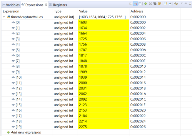
But what if we want to do something with it, like determining speed computations or time measurements? You should notice that the differences between values in the buffer are around 30 to 31 counts. If we averaged these counts, then it would be about ~30.5 counts between values.
Because SMCLK is the Timer_A clock source,
- Each count is 1 / (1 MHz) = 1 us.
- A difference of 30.5 counts between captures means that the rising edge occurs every 30.5 * 1 us = 30.5 us.
- Because ACLK is a periodic square wave, this means that the frequency of the signal is 1 / (30.5 us) = 32.78 kHz.
- This is very close to the 32.768 kHz ACLK source we are measuring
Averaging in software
A common application is to average these captures to determine frequency of a signal. To try this, start by adding this variable to the global variables:
unsigned int signalFreq = 0;
Now try writing your own code in the ISR to calculate the speed of ACLK and update the variable signalFreq with the correct frequency of ~32.678 kHz.
Start by copying the code below and adding your code to the "Add your code here" section.
If you need help, click on the "View Solution" tab at the bottom.
For more accurate results, try implementing an average of the buffer differences and/or increasing the buffer size by updating the #define NUMBER_TIMER_CAPTURES 20
to a larger buffer size.
    switch(__even_in_range(TA0IV,TA0IV_TAIFG))
    {
        case TA0IV_NONE:
            break;
        case TA0IV_TACCR1:
            break;
        case TA0IV_TACCR2:
            timerAcaptureValues[timerAcapturePointer++] = TA0CCR2;
            if (timerAcapturePointer >= NUMBER_TIMER_CAPTURES)
            {

                ....    // Add your code here

            }
            break;
        case TA0IV_TAIFG:
            break;
        default:
            break;
    }
Here is a working example.
    switch(__even_in_range(TA0IV,TA0IV_TAIFG))
    {
        case TA0IV_NONE:
            break;                                  // No interrupt
        case TA0IV_TACCR1:
            break;                                  // CCR1 not used
        case TA0IV_TACCR2:
            timerAcaptureValues[timerAcapturePointer++] = TA0CCR2;
            if (timerAcapturePointer >= NUMBER_TIMER_CAPTURES)
            {
                unsigned int i, difference; //implement average of capture buffer differences (19)
                long temp, sum = 0;

                //calculate difference between current value and previous value for buffer
                for (i=1;i<NUMBER_TIMER_CAPTURES;i++)
                {
                    if (timerAcaptureValues[i] < timerAcaptureValues[i-1])
                    {
                        //if prev value > new value, add 65535 then find difference
                        temp = timerAcaptureValues[i] + 65535;
                        difference = temp - timerAcaptureValues[i-1];
                    }
                    else
                    {
                        //if prev value < new value, find difference
                        difference = timerAcaptureValues[i] - timerAcaptureValues[i-1];
                    }

                    sum += difference;  //sum up all the differences
                }

                timerAcapturePointer = 0;
                sum = sum / NUMBER_TIMER_CAPTURES-1;         //take average of all differences
                signalFreq = (1000000 / sum) * 0.97; //calculate frequency (SMCLK/difference)
                __no_operation();
            }

            break;                                  // CCR2 not used
        case TA0IV_TAIFG:
            break;                                  // overflow
        default:
            break;
    }
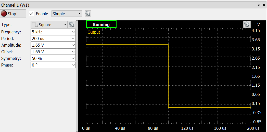
In the code above, we used a function generator to generate a 5 kHz PWM and used that as the input into P1.2 (CCI2A). The waveform is shown below:
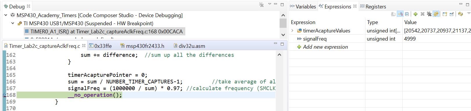
When the variable signalFreq is inserted into the Expressions window and a breakpoint is placed at __no_operation();, you can see the correct frequency of the square wave
as shown below:
Bonus Task – Creat a stopwatch
Instead of using ACLK as the input to the timer capture, use the pushbutton on the Launchpad (P2.7) to start and stop the timer.
- The stopwatch should start when the pushbutton is pressed and continue capturing until it is released.
- Use the female-to-female jumper to connect P2.7 on the Launchpad header to P1.2 to tie the Pushbutton to the TA0.CC2IA capture input.
- Light up LED1 when the timer starts, and light up LED2 when the timer stops.
A solution is included below for reference.
Here is a working example.
   #include <msp430.h>

    #define NUMBER_TIMER_CAPTURES        20

    volatile unsigned int timerAcaptureValues[NUMBER_TIMER_CAPTURES];
    unsigned int timerAcapturePointer = 0;
    unsigned int overflowCounter = 0;
    unsigned int startTime = 0;
    unsigned int endTime = 0;
    unsigned int edgeFlag = 0;
    float elapsedTime = 0.0;

    int main(void)
    {
        WDTCTL = WDTPW | WDTHOLD;                       // Stop watchdog timer

        // Configure GPIO
        P1DIR |= BIT0 | BIT1;                           // Set P1.0 as output
        P1OUT |= BIT0 | BIT1;                           // P1.0 high
        P1SEL1 |= BIT2;                                 // TA0.CCI2A input capture pin, second function
        P1REN |= BIT2;                                  // enable internal pull-down resistor
        P1OUT |= BIT2;

        // Disable the GPIO power-on default high-impedance mode to activate
        // previously configured port settings
        PM5CTL0 &= ~LOCKLPM5;

        // Configure clock
        __bis_SR_register(SCG0);                        // disable FLL
        CSCTL3 |= SELREF__REFOCLK;                      // Set REFO as FLL reference source
        CSCTL0 = 0;                                     // clear DCO and MOD registers
        CSCTL1 &= ~(DCORSEL_7);                         // Clear DCO frequency select bits first
        CSCTL1 |= DCORSEL_2;                            // Set DCO = 4MHz
        CSCTL2 = FLLD_1 + 60;                           // DCODIV = 2MHz
        __delay_cycles(3);
        __bic_SR_register(SCG0);                        // enable FLL
        while(CSCTL7 & (FLLUNLOCK0 | FLLUNLOCK1));      // Poll until FLL is locked

        CSCTL4 = SELMS__DCOCLKDIV | SELA__REFOCLK;      // set default REFO(~32768Hz) as ACLK source, ACLK = 32768Hz
                                                        // default DCODIV as MCLK and SMCLK source
        CSCTL5 |= DIVM__1 | DIVS__2;                    // SMCLK = 1MHz, MCLK = 2MHz

        // Timer0_A3 Setup
        TA0CCTL2 |= CM_3 | CCIS_0 | CCIE | CAP | SCS;
                                                        // Capture rising edge,
                                                        // Use CCI2A=ACLK,
                                                        // Synchronous capture,
                                                        // Enable capture mode,
                                                        // Enable capture interrupt

        TA0CTL |= TASSEL_1 | MC_2 | TACLR | TAIE;              // Use SMCLK as clock source, clear TA0R
                                                        // Start timer in continuous mode

        __bis_SR_register(LPM0_bits | GIE);
        __no_operation();
    }

    // Timer0_A3 CC1-2, TA Interrupt Handler
    #if defined(__TI_COMPILER_VERSION__) || defined(__IAR_SYSTEMS_ICC__)
    #pragma vector = TIMER0_A1_VECTOR
    __interrupt void TIMER0_A1_ISR(void)
    #elif defined(__GNUC__)
    void __attribute__ ((interrupt(TIMER0_A1_VECTOR))) TIMER0_A1_ISR (void)
    #else
    #error Compiler not supported!
    #endif
    {
        switch(__even_in_range(TA0IV,TA0IV_TAIFG))
        {
            case TA0IV_NONE:
                break;                                  // No interrupt
            case TA0IV_TACCR1:
                break;                                  // CCR1 not used
            case TA0IV_TACCR2:
                if (!edgeFlag)
                {
                    overflowCounter = 0;                //Reset number of overflows
                    P1OUT &= ~(BIT1);                   //Turn on red, turn off green
                    P1OUT |= BIT0;
                    startTime = 0;                      //Reset timer variable and CCR2, start timer in cont mode
                    TA0CCR2 = 0;
                    TA0CTL |= TACLR | MC_2;
                }
                else
                {
                    endTime = TA0CCR2;              //Stop timer
                    P1OUT &= ~(BIT0);               //Turn on green, turn off red
                    P1OUT |= BIT1;
                    TA0CTL |= MC_0;

                    //Time = # of overflows (2.0s each) + leftover portion of interval (0-2.0s)
                    //Ex) 4.5s = 2*(2.0s) + (16384/32678)

                    elapsedTime = (float)(2.0*(float)(overflowCounter)) + (float)((float)(endTime) / 32678.0);
                    __no_operation();
                }
                edgeFlag ^= 1;

                break;                                  // CCR2 not used
            case TA0IV_TAIFG:
                overflowCounter++;
                break;                                  // overflow
            default:
                break;
        }
    }
Summary
At the end of this lab, you should now be able to:
- Set up Timer_A in Capture mode by setting the TAxCCTLn register
- Perform a speed computation or time measurement using a capture buffer
This work is licensed under a Creative Commons Attribution-NonCommercial-NoDerivatives 4.0 International License.