Introduction
Working with Sensor Controller Studio (SCS) you (should, by now) have been introduced to concepts such as resources and procedures. A resource defines as way to interface with a given set of software or hardware functions while a procedure is the functions that can be called from the Sensor Controller task code. While SCS provide a rich set of resources and procedures to interface with the Sensor Controller and the surrounding peripherals, there is sometimes a need for tailormade procedures in order to make a specific task more efficient. This training will show you how to create and add customized resources and procedures to SCS.
In the training, a custom Quadrature Decoder resource will be implemented with
a few custom procedures. We will see how we can improve execution speed using
tailored procedures compared to implementing the Quadrature Decoder using
the procedure set that is available from start.
It is highly recommended to first complete the training modules listed under Completed Material before proceeding with this training. It is also recommended to have a basic knowledge about how to interpret and write assembly code given an instruction set.
The training is expected to require roughly 3 hours to complete so consider splitting it into multiple sessions.
Compatible SimpleLink MCU LaunchPad kits
This workshop can be completed with any one of the SimpleLink™ Wireless MCU with Sensor Controller devices described in the table below. Install the associated SimpleLink software development kit matching your device. For more details on LaunchPads please visit the LaunchPad overview page.
Prerequisites
Completed Material
- Sensor Controller Basics - Getting Started
- TI-RTOS Basics Lab 1
- Project from Scratch
- Capacitive Touch
Software for Desktop Development
In order to start with this training you will need to download the associated Software Development Kit (SDK) for your LaunchPad. This training covers the CC13x0, CC13xx, CC2640R2 and the CC26xx device families.
| Device | SDK downloads |
|---|---|
| CC13x0 | SimpleLink CC13x0 Software Development Kit |
| CC2640R2 | SimpleLink CC2640R2 Software Development Kit |
| CC13xx/ CC26xx | SimpleLink CC13xx/ CC26xx Software Development Kit |
In addition to downloading the relevant SDK for your choice of Launchpad, you also need the following software:
- Sensor Controller Studio version 2.7.0 or later
Hardware
One LaunchPad connected with a USB micro cable:
- LAUNCHXL-CC1310,
- LAUNCHXL-CC1312R1,
- LAUNCHXL-CC1350,
- LAUNCHXL-CC1352R1,
- LAUNCHXL-CC1352P,
- LAUNCHXL-CC26x2R1, or
- LAUNCHXL-CC2640R2.
Getting started
"What is a resource and what is a procedure in the context of Sensor Controller Studio?" you might be asking yourself by now. Let us start by explaining what a resource is.
Resources
A resource is as a gathering of procedures with a common purpose. If you are
familiar with C-language, you can think it as a library of functions. In
Sensor Controller Studio (SCS), resources are selected in the Task Resources
panel, controlling which features is made available in a given project. A
resource typically contains information on:
- Procedures that will be enabled (available when writing task code)
- Resource description and documentation
- HW/SW modules, used to check for conflicts between resources both within and across tasks
- I/O functions used by the resource
- Resource specific constants and data structure members
- Resource specific C source code to be included in the generated SCIF driver
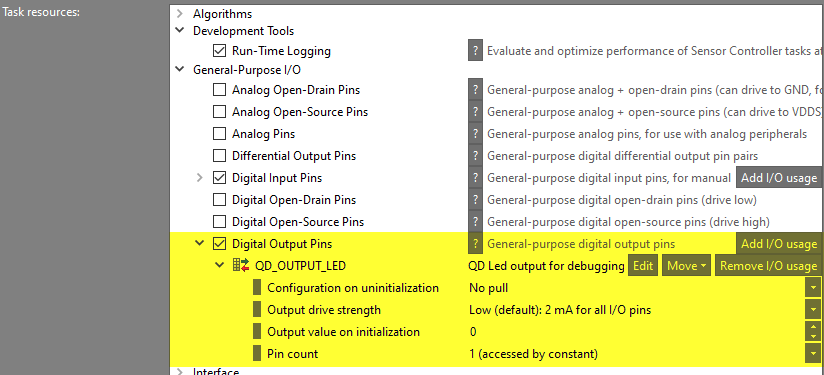
A basic resource example is the Digital Output Pins resource, which
enables one or more I/O pins with a given configuration:
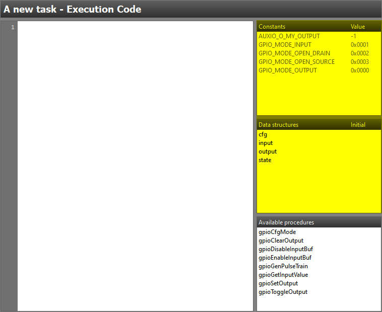
By selecting this resource, the following set of procedures available in the task code editor:
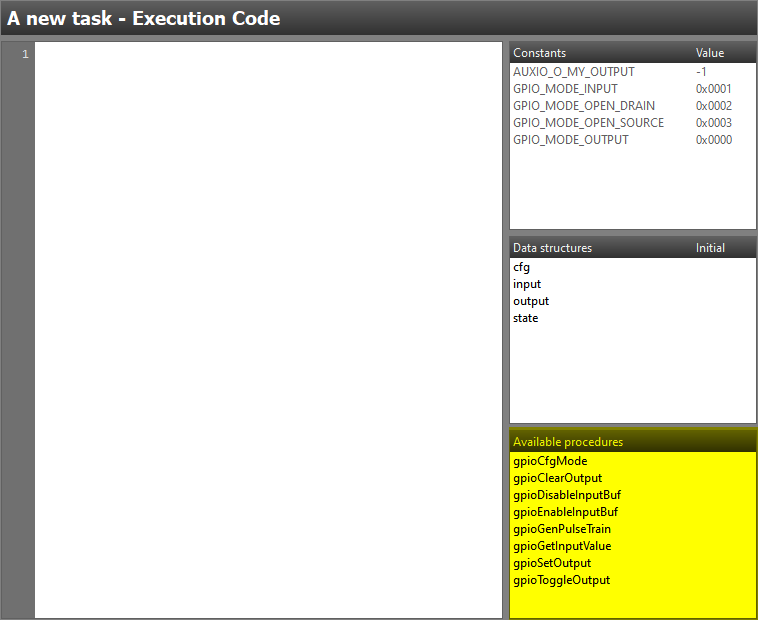
Selecting the resource also adds 5 new constants to the project but (in this case) no data structure members:
in this case?
Not all resources require pre-defined data structure memebers. There is a few standard resources in SCS that adds data structure members such as the I2C Master, UART emulator and LCD controller resources.
Procedures
A procedure is the Sensor Controller equivalent of a function in the C programming language. Procedures are written in assembly using the Sensor Controller Engine instruction set and is always bound to a specific resource.
Hey, where can I find the instruction set?
The Sensor Controller instruction set is documented inside both
the Sensor Controller Studio help viewer under
Assembly Language Reference or in the Sensor Controller chapter of the
Technical Reference Manual.
As we will look closer at how resources and procedures are implemented in practice in the scope of this lab, we will not cover this in more detail right now.
Software Setup
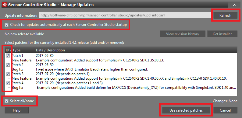
Start by installing Sensor Controller Studio and enable all patches. Patches
can be enabled by first clicking Updates → Check for Updates. If any
new patches are available, click Updates → Manage Updates... and
apply all new patches. Note that the picture below is only used as an example.
You may have a newer version, and there may be no patches available.
Once SCS is up and running, connect the Launchpad to the computer and open up
the ADC Window Monitor example. Try to start the "Run-Time Logging" to verify
that SCS and your LaunchPad works as expected before proceeding with the
training.
Task 1 – Create and Setup SCS Project
We will start with creating a new Sensor Controller project in SCS. To start
with we only require a simple project with two digital input pins acting as
our Quadrature Decoder input, a debug output pin and run-time logging.
In case this sounds unfamiliar, please see the
Project from Scratch training which covers how to
set up a project from scratch.
SCS Documentation and Help
At any time in SCS, Help – Sensor Controller Studio Help or press F1 for documentation and help.
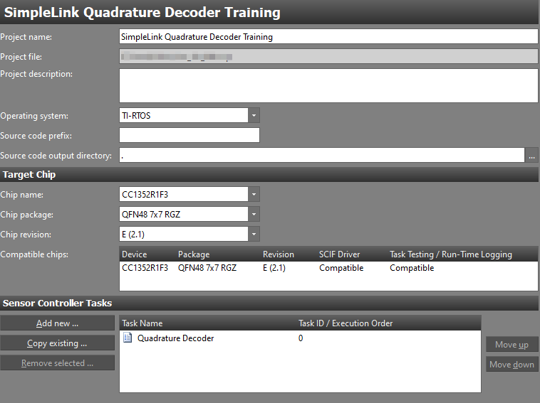
We start with creating the project:
- Start SCS and open a new project, File → New Project or Ctrl+N.
- Set the
Project NametoSimpleLink Quadrature Decoder Training. - Set the
Operating systemtoTI-RTOS. - Set
Source code output directoryto.. - Set
Chip namecorresponding to the device in use, e.g.:CC2640R2Fif using CC2640R2F.CC1352R1F3if using CC1352R1.
- Set
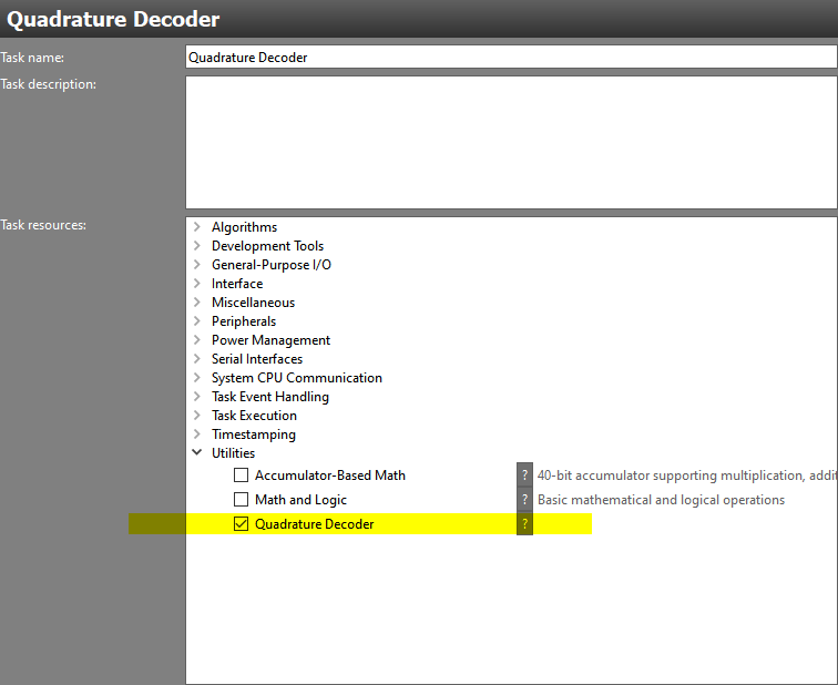
Chip packagetoQFN48 7x7 RGZ. - Add one task by clicking
Add new, name itQuadrature Decoder. - Save the project, File → Save Project or Ctrl+S.
Refer to the screen shot below for the CC1352R LaunchPad.
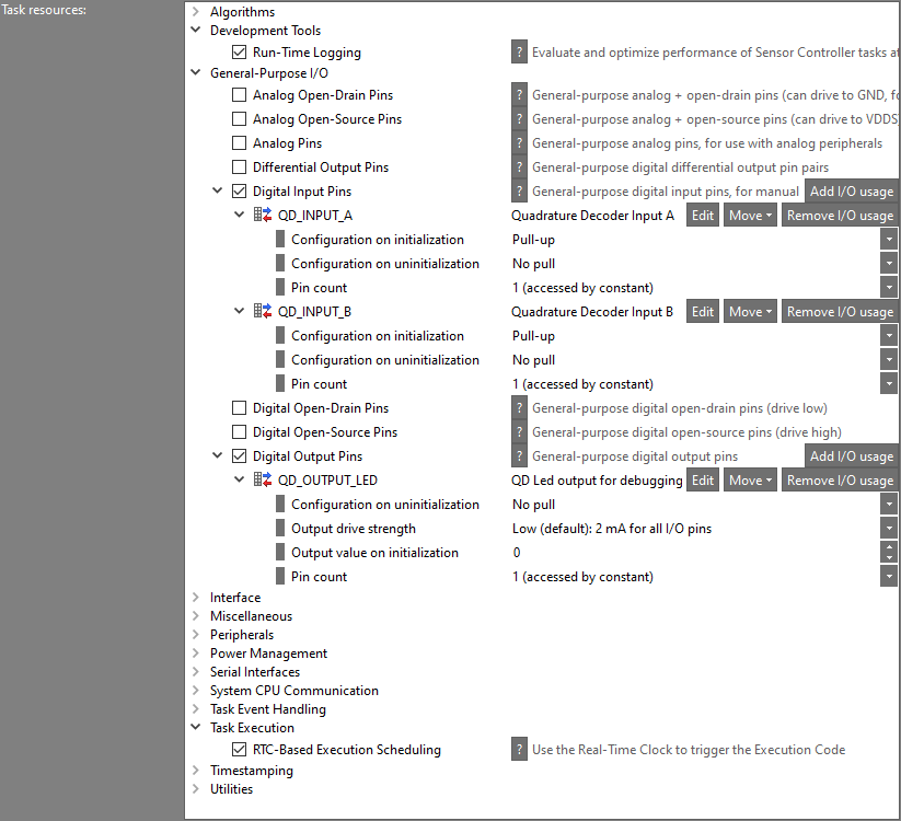
We now need to specify the resources to be used. Go to Task Properties for the
quadrature decoder task, which can be accessed by clicking on the task name in
the directory on the left hand side, above the Initialization Code. Select
the task resources in the list below.
- Run-Time Logging
- Digital Input Pins
- Create two pins and name them
QD_INPUT_AandQD_INPUT_Band configure them as pull-ups (this as we will later use the LaunchPad buttons as input). This does not yet include any physical I/O mapping, we will do this in the upcoming step.
- Create two pins and name them
- Digital Output Pins
- Create one pin and name it
QD_OUTPUT_LED.
- Create one pin and name it
- RTC-Based Execution Scheduling
Make sure the Task resource settings match the screenshot below:
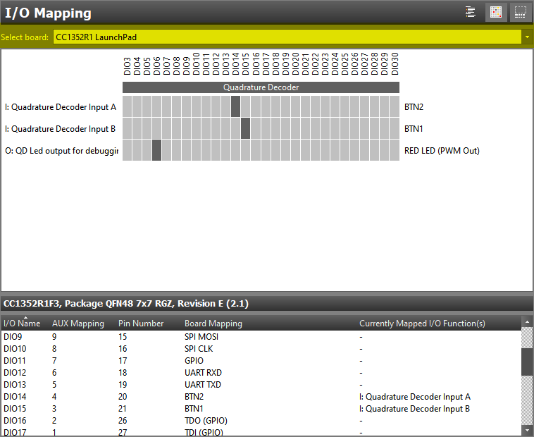
I/O Mapping
Finally, we need to setup the I/O Mapping for our pins. The exact mapping is
up to you as the reader to decide but the suggestion is to use the LaunchPad
buttons as QD_INPUT_A and QD_INPUT_B as well as one of the LEDs as
QD_OUTPUT_LED.
For the CC1352R LaunchPad, this would result in a setup along the lines of:
- Digital input pin
QD_INPUT_AtoDIO14akaBTN2. - Digital input pin
QD_INPUT_BtoDIO15akaBTN1. - Digital output pin
QD_OUTPUT_LEDtoDIO6akaRED LED.
The pin order can vary. In the I/O Mapping view you can at the top select
which board you are using. For instance, select the CC1352R1 LaunchPad if you
are using a CC1352R1 LaunchPad.
Hey, I can't assign the buttons for my LaunchPad!
You are likely doing the training on a CC13x0 or CC26x0 LaunchPad device where the available set if I/Os is limited. If this is the case, the suggestion is to select any two available pins and connect these pins to the I/Os connected to the LaunchPad buttons using jumper wires.
Task 2 – Initial Quadrature Decoder Implementation
Before looking into the actual implementation, we will quickly touch on what a quadrature decoder is and what we will try to implement in software. We will only cover what is important for this training without going into to much detail.
Quadrature Encoded Signals
Quadrature encoded signals is typically used to measure angular displacement of mechanical devices such as a motor or water meter. The quadrature encoder has an incremental output type which means that it outputs "rotation step" instead of absolute position. By encoding the rotation onto the two output signals, A and B, with a 90 degrees phase shift, a gray coded signal is created as seen in the GIF image below.
The GIF image showcase the four possible gray code states, labeled as 0, 1, 2 and 3. By tracking state changes, the direction, relative position and speed of the rotation can be determined. For example, consider a motor rotating in one direction where signal A leads signal B, the state changes would be 0 → 1 → 3 → 2 → 0 → 1 etc. If the motor were to rotate in the opposite direction then signal B would lead signal A and the state changes would be 0 → 2 → 3 → 1 → 0 → 2 etc.
While tracking the state changes gives us information about the direction of the rotation as well as relative position, measuring the interval gives us information about velocity. To calculate the latter, one needs to know the numbers of state changes per full rotation. In this training we will focus on the direction and leave out relative position and velocity.
Want a better explanation?
To get a better understanding of quadrature encoders and decoders it is recommended to use the search engine of your choice to find some additional reading.
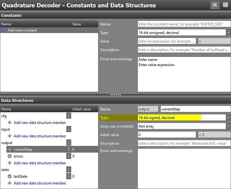
Adding Data Structure Members
Before we get to writing code, we need to first make a quick stop by the
Constants and Data Structures view. We need three data structure members:
- One to track the current step count
- One to track the last state
- One to count the number of invalid state transitions
What is an "invalid state transition"?
An invalid state transition is when both inputs change value. A valid state transition occur when only one input changes.
The first variable, named currentStep, belongs to the output data structure
while the second variable, named lastState, belongs to the state structure.
The remaining variable, errors, should also be placed in the output
structure. If you are unsure on why we use the structures above, consider the
table below (the same information can be found in the Sensor Controller Studio
help section):
| Data structure | Intended use |
|---|---|
| cfg | Configuration of SC Task |
| input | Input data for SC Task |
| output | Output data from SC Task |
| state | Internal state of SC Task |
As we can expect rotation in two direction, the state count variable will need to be a signed variable. This as we either increment or decrement the count depending on the direction of the rotation. When done, you should have something along the lines of the picture below.
Initialization Code
We can now start implementing our quadrature decoder application. In the first version we will only use the standard SCS procedure set and resources and have a look at the resulting code.
We start with the Initialization Code block which we use to setup the I/O
configuration, read the initial input state and then schedule the first run
of theExecution Code block. For the purpose of moving this training along
faster, a ready made code snippet is provided below.
// Set pin mode
gpioCfgMode(AUXIO_I_QD_INPUT_A, GPIO_MODE_INPUT);
gpioCfgMode(AUXIO_I_QD_INPUT_B, GPIO_MODE_INPUT);
gpioCfgMode(AUXIO_O_QD_OUTPUT_LED, GPIO_MODE_OUTPUT);

// Enable input buffers on inputs
gpioEnableInputBuf(AUXIO_I_QD_INPUT_A);
gpioEnableInputBuf(AUXIO_I_QD_INPUT_B);

// Read initial state
U16 inputA;
U16 inputB;
gpioGetInputValue(AUXIO_I_QD_INPUT_A; inputA);
gpioGetInputValue(AUXIO_I_QD_INPUT_B; inputB);

// Convert to "last state", inputB should be bit1 and inputA bit0
state.lastState = (inputB << 1) | inputA;

// Schedule first run of the Execution Code
fwScheduleTask(1);
Initialization Code – Initial pin configuration setup
Execution Code
The Execution Code block contains the main logic of our quadrature decoder
implementation. For simplicity, we design the execution code to never return.
We do this to easier measure the execution speed of this and future versions
of the quadrature decoder as it would correspond to the fastest possible sample
rate.
Be careful with infinite loops!
In this training we for simplicity use a never returning loop in out execution code block. A consequence of this is that the application cannot be stopped once started.
In a "real" application, it is recommended to add a option for the user to stop the loop. This can for example be done using a data structure variable as the loop condition variable as it can be modified by the user from the system CPU side.
Taking all of this into consideration, the steps we need to cover during each loop itteration is:
- Read the current input value of
QD_INPUT_AandQD_INPUT_B - Convert input values to a state as described in Quadrature Encoded Signals
- Compare the new state with the last state to determine direction
- Update output variables according to the state change
- Update the value of
lastStateand schedule next reading - Log
outputandstatestructures using the Run-Time Logging - Toggle the output LED so that we can measure the loop execution time externally
As in the case of the Initialization Code, a ready made code snippet is
available below.
U16 end = 0;

do {
    // Read input values
    U16 inputA;
    U16 inputB;
    gpioGetInputValue(AUXIO_I_QD_INPUT_A; inputA);
    gpioGetInputValue(AUXIO_I_QD_INPUT_B; inputB);

    // Convert to "new state"
    U16 newState = (inputB << 1) | inputA;

    // Check state transition
    U16 lastState = state.lastState;
    if (newState != lastState) {
      // Assume a "negative" direction per default
      U16 direction = 0;
      U16 error = 0;

      // If last state was "0", valid transitions are to "1" or "2".
      // As negative direction is assumed, we do not need to check for "2"
      if (lastState == 0) {
          if (newState == 1) {
              // If state changes to "1" then the direction is "positive"
              direction = 1;
          } else if (newState == 3) {
              error = 1;
          }

      // If last state was "1", valid transitions are to "3" or "0"
      // As negative direction is assumed, we do not need to check for "0"
      } else if (lastState == 1) {
          if (newState == 3) {
              // If state changes to "3" then the direction is "positive"
              direction = 1;
          } else if (newState == 2) {
              error = 1;
          }

      // If last state was "2", valid transitions are to "0" or "3"
      // As negative direction is assumed, we do not need to check for "3"
      } else if (lastState == 2) {
          if (newState == 0) {
              // If state changes to "0" then the direction is "positive"
              direction = 1;
          } else if (newState == 1) {
              error = 1;
          }

      // If last state was "3" (as it was not 0-2) , valid transitions are to "2" or "1"
      // As negative direction is assumed, we do not need to check for "1"
      } else {
          if (newState == 2) {
              // If state changes to "2" then the direction is "positive"
              direction = 1;
          } else if (newState == 0) {
              error = 1;
          }
      }

      // Update output variables accordingly
      if (error == 0) {
          if (direction == 1) {
              output.currentStep += 1;
          } else {
              output.currentStep -= 1;
          }
      } else {
          output.errors += 1;
      }

      // Log structures
      rtlLogStructs(BV_RTL_LOG_OUTPUT | BV_RTL_LOG_STATE);
    }

    // Update last state
    state.lastState = newState;

    // Toggle debug LED
    gpioToggleOutput(AUXIO_O_QD_OUTPUT_LED);

// This loop will never break
} while(end == 0);
Execution Code – First quadrature decoder solution
Looking at the code, we can see that it is quite straightforward. We sample each pin and then compare the new state with the old state. Ideally we would like to sample both inputs at the same time, but using the normal procedures, this is not possible. The notion of positive and negative direction in the code is in relation to the rotation direction disgusted in the Quadrature Encoded Signal section.
Why are we reading the lastState into a local variable?
Some of you might have noted that we do not perform checks against
the state.lastState variable directly. Instead we read state.lastState
into a local variable that we later use to check against.
We do this to allow the compiler to make more efficient code as we need
to use the value more then once. This as using state.lastState directly
would result in the compiler performing a "load and compare" operation each
time as the value is not in a register (and is considered volatile). If we
instead load the value into a local variable then the compiler can re-use
the same register for all subsequent checks, saving all the subsequent
"load" operations.
Testing the Code
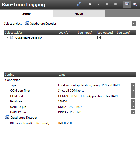
It is now time to test the first version of our quadrature decoder application and we do this using the Run-Time Logging feature in SCS. It is expected that you are familiar with this from before, if not, take some time and look over the Capacitive Touch training module before proceeding.
In the Run-Time Logging view, select that "Log output?" and "Log state?" as
these are the two data structure currently we use in our project. Setup the
COM port to match the LaunchPad you are currently using and leave the RTC
tick interval with the default value as it is only used to trigger the first
run of the Execution Code block. The setup should look like in the picture
below.
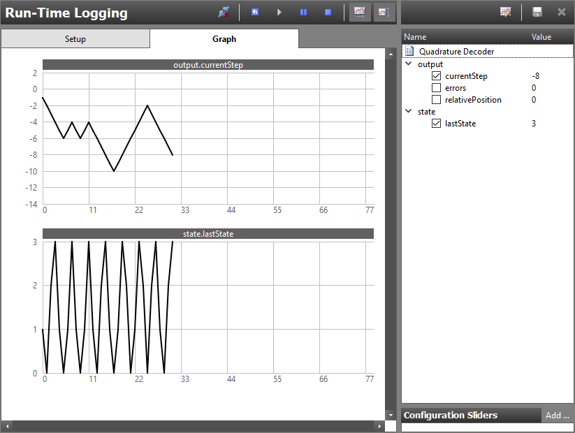
Now Connect (F12) to the device and Start Run-Time Logging
(F5). If everything is working as expected, you will not see any
structure updates happening. We can now start playing around with the push
buttons to move between different states and see how the currentStep variable
counts either up or down.
SCS test limitations
The Sensor Controller task code should normally not run continuously in a loop. If that is the case:
Once the task is running, it cannot be stopped or restarted. Using the Stop and Restart commands will cause an error.
Once the task is running, any attempt to edit data structure member or using a configuration slider will cause an error.
I can't seem to trigger any invalid state transitions
By now you might have tried to perform an invalid state transition (e.g. moving from state "3" to state "0") but without any luck getting the error count to increase. This is due to the execution speed of our loop and the fact that the manual button presses are unlikely to be synchronized with each other.
If you would like to verify that you can actually catch invalid states you can mount a jumper on the two DIOs representing the button inputs to trigger a "synchronized" state change.
Digging into the Assembly Code
Now that we have verified that our initial attempt to create a quadrature decoder
works, let us look closer at the limitations with this solution and why it is not
the most efficient solution. To do this we need to have a look at the resulting
assembly code that is generated based on the code we have written. The easiest
way to do so is to look at the listing file generated by SCS when using the
Code Generator feature.
To find the listing file, you first need to perform a code generation by
clicking the the Output SCIF driver files button in the Code Generator view.
Once the output has been generated, the output directory can be opened by
clicking the View output directory button. In this folder there should be a
file named sce.lst which is the file we want to look closer at.
At a first glance we can see that there is a lot of "framework" code that is
automatically added to the output but that is not part of our code segments.
We will not spend time making sense of this but instead navigate to the
the line where the Execution Code block starts. An easy way to find
this is searching for "quadratureDecoder/execute". A small snippet of what you
can expect to find is seen below.
  ...

  quadratureDecoder/execute:
                ;? U16 end = 0;
  00d8 ---- 0000                         ld          R0, #0
                ;?
                ;? do {
                /id0068:
                ;?     // Read input values
                ;?     U16 inputA;
                ;?     U16 inputB;
                ;?     gpioGetInputValue(AUXIO_I_QD_INPUT_A; inputA);
  00d9 ---- 7004                             ld          R7, #4
  00da ---- 1527                             jsr         gpioGetInputValue
  00db ---- 9d47                             ld          R1, R7
                ;?     gpioGetInputValue(AUXIO_I_QD_INPUT_B; inputB);
  00dc ---- 7003                             ld          R7, #3
  00dd ---- 1527                             jsr         gpioGetInputValue
                ;?
                ;?     // Convert to "new state"
                ;?     U16 newState = (inputB << 1) | inputA;
  00de ---- ed47                             ld          R6, R7
  00df ---- eda1                             lsl         R6, #1
  00e0 ---- ed09                             or          R6, R1

  ...
Generated assembly output
As seen in the snippet above, one can easily correlate our "task code" (marked with a ";?" in the start of the line) and the resulting assembly code which was produced as a result of this. In the snippet below we can for example see that reading input A results in two "load" (ld) instructions as well as a "jump to subroutine" (jsr) instruction.
                ;?     // Read input values
                ;?     U16 inputA;
                ;?     U16 inputB;
                ;?     gpioGetInputValue(AUXIO_I_QD_INPUT_A; inputA);
  00d9 ---- 7004                             ld          R7, #4
  00da ---- 1527                             jsr         gpioGetInputValue
  00db ---- 9d47                             ld          R1, R7
Correlation between task code and resulting assembly, part 1
Let us analyze how many instructions that is actually needed to read the input. To do this we need to search for "gpioGetInputValue" in the file to see how the subroutine is written:
  ; PARAMETERS:
  ;     R7 = AUX I/O index
  ;
  ; CLOBBERS:
  ;     R6, R7
  gpioGetInputValue:
                          ; Calculate the I/O bit index
  0127 ---- ed47                         ld          R6, R7
  0128 ---- e007                         and         R6, #0x0007

                          ; Calculate the I/O register address
  0129 ---- fdab                         lsr         R7, #3
  012a 8600 f8be                         add         R7, #IOP_AIODIO0_GPIODIN

                          ; Move the desired GPIO pin value into bit 0 and mask
  012c ---- ff07                         in          R7, [R7]
  012d ---- fd8e                         lsr         R7, R6
  012e ---- f001                         and         R7, #0x0001
  012f ---- adb7                         rts
Correlation between task code and resulting assembly, part 2
Counting the instructions in the gpioGetInputValue subroutine, we can see that
it requires 8 instructions in total including the subroutine return (rts).
If we add in the two instructions surrounding the initial jsr call we get a
total of 10 instructions to read an input. Finally, we account for the prefixed
instructions which means we get a final value of 11 instructions. What does this
mean for our application? To understand this we need to consider the number of
clock cycles it takes to execute a typical instruction on the Sensor Controller.
Most Sensor Controller instructions use two clock cycles. This means that the efficient instruction execution rate is more or less half that of the clock that drives the Sensor Controller Engine. There is some exception from this rule where accesses to ADI and DDI registers, prefixed instructions, and wait instructions require additional cycles. For detailed information on this, please refer to the Technical Reference Manual or the SCS help section.
Prefixed instruction?
A "prefixed" instruction can be spotted by looking at the second column to the left in the listing file. A prefixed instruction require additional clock cycles to complete which means we count it as two instruction worth of execution time.
In the current application, the Sensor Controller operates in Active Mode
which means the Sensor Controller executes (up to) 12 instructions per
microsecond. If we convert this to time it means each instruction takes roughly
83.3 ns to execute and that 11 instructions require roughly 916.3 ns of
execution time.
While this might not seem like a lot if time, we want to sample the two inputs with as little delay as possible to avoid errors. We also need to consider that that this time impacts how fast our application loop will run, directly relating to the maximum state change rate that the implementation can potentially handle. We will revisit this in a bit but for now we will continue on and analyze the rest of the loop. As we have already looked over the assembly relating to reading the inputs, lets now look over the part responsible for checking the state and incrementing the counter.
              ;?     // Convert to "new state"
              ;?     U16 newState = (inputB << 1) | inputA;
00de ---- ed47                             ld          R6, R7
00df ---- eda1                             lsl         R6, #1
00e0 ---- ed09                             or          R6, R1
              ;?
              ;?     // Check state transition
              ;?     U16 lastState = state.lastState;
00e1 ---- 18bb                             ld          R1, [#quadratureDecoder/state/lastState]
              ;?     if (newState != lastState) {
00e2 ---- ed29                             cmp         R6, R1
00e3 ---- b63a                             beq         /id0080
              ;?       // Assume a "negative" direction per default
              ;?       U16 direction = 0;
00e4 ---- 7000                               ld          R7, #0
              ;?       U16 error = 0;
00e5 ---- 2000                               ld          R2, #0
              ;?
              ;?       // If last state was "0", valid transitions are to "1" or "2"
              ;?       if (lastState == 0) {
00e6 ---- 9a00                               cmp         R1, #0
00e7 ---- be08                               bneq        /id0085
              ;?           if (newState == 1) {
00e8 ---- ea01                                   cmp         R6, #1
00e9 ---- be02                                   bneq        /id0088
              ;?               // If state changes to "1" then the direction is "positive"
              ;?               direction = 1;
00ea ---- 7001                                       ld          R7, #1
              ;?           } else if (newState == 3) {
00eb ---- 04ef                                   jmp         /id0090
              /id0088:
00ec ---- ea03                                   cmp         R6, #3
00ed ---- be01                                   bneq        /id0092
              ;?               error = 1;
00ee ---- 2001                                       ld          R2, #1
              ;?           }
              /id0092:
              /id0090:
              ;?
              ;?       // If last state was "1", valid transitions are to "3" or "0"
              ;?       // As negative direction is assumed, we do not need to check for "0"
              ;?       } else if (lastState == 1) {
00ef ---- 050b                               jmp         /id0087
              /id0085:
00f0 ---- 9a01                               cmp         R1, #1
00f1 ---- be08                               bneq        /id0095
              ;?           if (newState == 3) {
00f2 ---- ea03                                   cmp         R6, #3
00f3 ---- be02                                   bneq        /id0098
              ;?               // If state changes to "3" then the direction is "positive"
              ;?               direction = 1;
00f4 ---- 7001                                       ld          R7, #1
              ;?           } else if (newState == 2) {
00f5 ---- 04f9                                   jmp         /id0100
              /id0098:
00f6 ---- ea02                                   cmp         R6, #2
00f7 ---- be01                                   bneq        /id0102
              ;?               error = 1;
00f8 ---- 2001                                       ld          R2, #1
              ;?           }
              /id0102:
              /id0100:
              ;?
              ;?       // If last state was "2", valid transitions are to "0" or "3"
              ;?       } else if (lastState == 2) {
00f9 ---- 050b                               jmp         /id0097
              /id0095:
00fa ---- 9a02                               cmp         R1, #2
00fb ---- be08                               bneq        /id0105
              ;?           if (newState == 0) {
00fc ---- ea00                                   cmp         R6, #0
00fd ---- be02                                   bneq        /id0108
              ;?               // If state changes to "0" then the direction is "positive"
              ;?               direction = 1;
00fe ---- 7001                                       ld          R7, #1
              ;?           } else if (newState == 1) {
00ff ---- 0503                                   jmp         /id0110
              /id0108:
0100 ---- ea01                                   cmp         R6, #1
0101 ---- be01                                   bneq        /id0112
              ;?               error = 1;
0102 ---- 2001                                       ld          R2, #1
              ;?           }
              /id0112:
              /id0110:
              ;?
              ;?       // If last state was "3" (as it was not 0-2) , valid transitions are to "2" or "1"
              ;?       } else {
0103 ---- 050b                               jmp         /id0107
              /id0105:
              ;?           if (newState == 2) {
0104 ---- ea02                                   cmp         R6, #2
0105 ---- be02                                   bneq        /id0115
              ;?               // If state changes to "2" then the direction is "positive"
              ;?               direction = 1;
0106 ---- 7001                                       ld          R7, #1
              ;?           } else if (newState == 0) {
0107 ---- 050b                                   jmp         /id0117
              /id0115:
0108 ---- ea00                                   cmp         R6, #0
0109 ---- be01                                   bneq        /id0119
              ;?               error = 1;
010a ---- 2001                                       ld          R2, #1
              ;?           }
              /id0119:
              /id0117:
              ;?       }
              /id0107:
              /id0097:
              /id0087:
              ;?
              ;?       // Update output variables accordingly
              ;?       if (error == 0) {
010b ---- aa00                               cmp         R2, #0
010c ---- be0a                               bneq        /id0122
              ;?           if (direction == 1) {
010d ---- fa01                                   cmp         R7, #1
010e ---- be04                                   bneq        /id0125
              ;?               output.currentStep += 1;
010f ---- 18b8                                       ld          R1, [#quadratureDecoder/output/currentStep]
0110 ---- 9801                                       add         R1, #1
0111 ---- 1cb8                                       st          R1, [#quadratureDecoder/output/currentStep]
              ;?           } else {
0112 ---- 0516                                   jmp         /id0127
              /id0125:
              ;?               output.currentStep -= 1;
0113 ---- 18b8                                       ld          R1, [#quadratureDecoder/output/currentStep]
0114 ---- 98ff                                       add         R1, #-1
0115 ---- 1cb8                                       st          R1, [#quadratureDecoder/output/currentStep]
              ;?            }
              /id0127:
              ;?       } else {
0116 ---- 051a                             jmp         /id0124
              /id0122:
              ;?           output.errors += 1;
0117 ---- 18b9                                   ld          R1, [#quadratureDecoder/output/errors]
0118 ---- 9801                                   add         R1, #1
0119 ---- 1cb9                                   st          R1, [#quadratureDecoder/output/errors]
              ;?       }
              /id0124:
              ;?
              ;?       // Log structures
              ;?       rtlLogStructs(BV_RTL_LOG_OUTPUT | BV_RTL_LOG_STATE);
011a ---- 100c                               ld          R1, #12
011b ---- 28ab                               ld          R2, [#(pRtlTaskLogMaskTable + 0)]
011c ---- 9d02                               and         R1, R2
011d ---- 1caa                               st          R1, [#(pRtlTaskLogReqTable + 0)]
              ;?     }
              /id0080:
              ;?
              ;?     // Update last state
              ;?     state.lastState = newState;
011e ---- 6cbb                             st          R6, [#quadratureDecoder/state/lastState]
              ;?
              ;?     // Toogle debug LED
              ;?     gpioToggleOutput(AUXIO_O_QD_OUTPUT_LED);
011f ---- 74cb                             iobset      #(12 & 0x7), [#(IOP_AIODIO0_GPIODOUTTGL + (12 >> 3))]
              ;?
              ;?     // This loop will never break
              ;? } while(end == 0);
0120 ---- 8a00                         cmp         R0, #0
0121 ---- b6b7                         beq         /id0070
Correlation between task code and resulting assembly, part 3
At a first glance it might look like a lot but if we limit our analyzing to find out the worst case execution path, we can ignore the three first if-statements. We can do this as the worst case execution time is when the last state was "3" and the initial "last state checks" return false. This means the worst case assembly path can be condensed down to:
                ;?     // Convert to "new state"
                ;?     U16 newState = (inputB << 1) | inputA;
  00de ---- ed47                             ld          R6, R7
  00df ---- eda1                             lsl         R6, #1
  00e0 ---- ed09                             or          R6, R1
                ;?
                ;?     // Check state transition
                ;?     U16 lastState = state.lastState;
  00e1 ---- 18bb                             ld          R1, [#quadratureDecoder/state/lastState]
                ;?     if (newState != lastState) {
  00e2 ---- ed29                             cmp         R6, R1
  00e3 ---- b63b                             beq         /id0080
                ;?         // Assume a "negative" direction per default
                ;?         U16 direction = 0;
  00e4 ---- 7000                                 ld          R7, #0
                ;?         U16 error = 0;
  00e5 ---- 2000                                 ld          R2, #0
                ;?
                ;?         // If last state was "0", valid transitions are to "1" or "2"
                ;?         if (lastState == 0) {
  00e5 ---- 9a00                                 cmp         R1, #0
  00e6 ---- be0a                                 bneq        /id0085

  ...

                ;?         // If last state was "1", valid transitions are to "3" or "0"
                ;?         } else if (lastState == 1) {
                  ...
                /id0085:
  00f1 ---- 9a01                                 cmp         R1, #1
  00f2 ---- be0a                                 bneq        /id0095

  ...

                ;?         // If last state was "2", valid transitions are to "0" or "3"
                ;?         } else if (lastState == 2) {
                  ...
                /id0095:
  00fd ---- 9a02                                 cmp         R1, #2
  00fe ---- be0a                                 bneq        /id0105

  ...

                ;?         // If last state was "3" (as it was not 0-2) , valid transitions are to "2" or "1"
                ;?         } else {
                  ...
                /id0105:
                ;?             if (newState == 2) {
  0109 ---- ea02                                     cmp         R6, #2
  010a ---- be02                                     bneq        /id0115
                ;?                 // If state changes to "2" then the direction is "positive"
                ;?                 direction = 1;
  0106 ---- 7001                                         ld          R7, #1
                ;?             } else if (newState == 0) {
  0107 ---- 050b                                     jmp         /id0117

  ...

                /id0117:
                ;?         // Update output variables accordingly
                ;?         if (error == 0) {
  010b ---- aa00                                 cmp         R2, #0
  010c ---- be0a                                 bneq        /id0122
                ;?          if (direction == 1) {
  0112 ---- fa01                                  cmp         R7, #1
  0113 ---- be04                                  bneq        /id0125
                ;?             output.currentStep += 1;
  0114 ---- 18b8                                     ld          R1, [#quadratureDecoder/output/currentStep]
  0115 ---- 9801                                     add         R1, #1
  0116 ---- 1cb8                                     st          R1, [#quadratureDecoder/output/currentStep]
                ;?         } else {
  0117 ---- 051b                                 jmp         /id0127

  ...

                /id0127:
               ;?         } else {
  0116 ---- 051a                                 jmp         /id0124

 ....

               /id0124:
               ;?
               ;?         // Log structures
               ;?         rtlLogStructs(BV_RTL_LOG_OUTPUT | BV_RTL_LOG_STATE);
011b ---- 100c                                 ld          R1, #12
011c ---- 78ab                                 ld          R7, [#(pRtlTaskLogMaskTable + 0)]
011d ---- 9d07                                 and         R1, R7
011e ---- 1caa                                 st          R1, [#(pRtlTaskLogReqTable + 0)]
               ;?     }
               /id0080:
               ;?
               ;?     // Update last state
               ;?     state.lastState = newState;
011f ---- 6cbb                             st          R6, [#quadratureDecoder/state/lastState]
               ;?
               ;?     // Toogle debug LED
               ;?     gpioToggleOutput(AUXIO_O_QD_OUTPUT_LED);
0120 ---- 74cb                             iobset      #(12 & 0x7), [#(IOP_AIODIO0_GPIODOUTTGL + (12 >> 3))]
               ;?
               ;?     // This loop will never break
               ;? } while(end == 0);
0121 ---- 8a00                         cmp         R0, #0
0122 ---- b6b6                         beq         /id0070
Condensed worst case execution path
Looking at the condensed assembly, we can see that the second part of our application loop (our Execution Code do-while loop) requires at most 35 instructions to run. If we add to this the 22 instructions required to sample the input pins in the top of the loop, we have a total of 57 instructions. This means our initial attempt at an quadrature decoder application results in execution time of roughly 4.75us for the worst case scenario.
Well that is not too shabby, let us wrap up?
While this might sound like a reasonable execution speed, we are not yet done.
First of all, we want to be more efficient, we want to go faster! We are also concerned about the delay between the sampling of the two input pins. It is time to create our first custom procedure!
Task 3 – Adding Procedures to Existing Resources
The first thing we can improve in our initial application is the input pin sampling which right now takes 22 cycles. From an application point of view, we want to be able to sample the differential state of two inputs as fast as possible. Unfortunately there is no such procedure available, we will need to address that.
We could at this point choose to add both a new resource and a new procedure, or we could extend an existing resource with a new procedure. We will go with option two and "only" add a new I/O procedure to read differential inputs. This means we can focus on the procedure files for now.
Creating a Procedure File
During the SCS installation, a local user folder is created in the local users
Document directory:
C:\Users\<WIN_USER>\Documents\Texas Instruments\Sensor Controller Studio.
Here we can add, among other things, our own procedures and resources. We will
start by creating a new procedure file inside the proc_def subfolder named
gpio_get_input_pair_state.prd:
C:\Users\<WIN_USER>\Documents\Texas Instruments\Sensor Controller Studio\proc_def\gpio_get_input_pair_state.prd
and open it up in the text editor of your choice.
Procedure file-ending
As can be seen in the file name above, the file-ending for a procedure file
is .prd.
Before we can put any content in the file, we need to open up the
"procedure definition" file which contains the information we need to write a
procedure file. This file is called proc_def.dtd and is found inside the
proc_def folder of the SCS installation path, e.g:
C:\Program Files (x86)\Texas Instruments\Sensor Controller Studio\proc_defs\proc_def.dtd.
Hey wait, is there multiple proc_def folders?
Yes! There is one proc_def folder inside the SCS installation directory
which contains all pre-defined procedures like those used in Task 2.
The proc_def folder found in the user document directory is meant for
users that need to extend on the existing set of procedures in order to
keep the installation directory clean.
With both of these files open, it is time for us to add content to our new procedure. We start by specify the XML version and document type at the top of our procedure file:
<?xml version="1.0" encoding="ISO-8859-15"?>
<!DOCTYPE proc_def SYSTEM "proc_def.dtd"[]>
gpio_get_input_pair_state.prd – Common procedure file header
We can now follow the documentation found inside proc_def.dtd to build up our
procedure from the grounds up. It is recommended to take the time to read over
this documentation before continuing.
How do I make any sense of this file?!
The proc_def.dtd is a XML Document Type Definition (DTD) file and reads as such.
This training will not cover the details on DTD syntax but further reading
can be found here.
For the reminder of the task, we will be referring to the proc_def.dtd as the
"DTD file".
Adding the "proc_def" Element
The first element we need to add to our procedure file is the proc_def
element. Looking at the DTD file we see that it needs to include the following
child elements:
| Element | Used for | Number of occurrences |
|---|---|---|
| desc | Procedure description/documentation | Once only |
| task_resource_ref | Linking the procedure with resources | Minimum of one |
We also see that it allows the following optional child elements:
| Element | Used for | Number of occurrences |
|---|---|---|
| chip_family_migration | Chip migration specific filtering | Zero or once only |
| run_time_logging | Procedures using to run-time logging | Zero or once only |
| impl | Procedure functional implementation | Any number |
| param | Input arguments to procedure | Any number |
| return | Procedure return values | Any number |
| internal | Internal procedure working variables | Any number |
| code | Procedure assembly code | Zero or once / impl |
| asm_file_dep | External assembly file references | Any number |
We also see that the proc_def element requires the following attributes:
| Element | Used for |
|---|---|
| name | Defining procedure name |
| version | Procedure version |
The name attribute equals to the task code API name we want for our new
procedure. Let us add this element to our new procedure file and give it the
name gpioGetInputPairState and version 1.0.0:
<?xml version="1.0" encoding="ISO-8859-15"?>
<!DOCTYPE proc_def SYSTEM "proc_def.dtd"[]>
<proc_def name="gpioGetInputPairState" version="1.0.0">
  ...
</proc_def>
gpio_get_input_pair_state.prd – Added proc_def element
Adding the "desc" Child
We now need to add the required desc child element. In the DTD
file we can see that it will contain parsed character data (PCDATA). The
desc child element provides the procedure description/documentation to the
SCS IDE. The description can be written in basic HTML, typically using p, b,
i, tt, ul and li tags.
<?xml version="1.0" encoding="ISO-8859-15"?>
<!DOCTYPE proc_def SYSTEM "proc_def.dtd"[]>
<proc_def name="gpioGetInputPairState" version="1.0.0">
  <desc>
    <![CDATA[
        <p>
        Returns the state of a given pin pair A and B.
        </p> <p>
        The state is the combined value of input A and B where input A is bit 0 and input B is bit 1.
        This means possible state values are 0, 1, 2 or 3.
        </p>
    ]]>
  </desc>
  ...
</proc_def>
gpio_get_input_pair_state.prd – Added procedure description
Adding the "task_resource_ref" Child
Now we need to add at least one task_resource_ref child element. The
task_resource_ref connects the procedure to a resource. In short terms, it
specifies for which resource this procedure should be made available. As we aim
to extend the existing set of "I/O procedures" we should make our new procedure
available for the following task resources:
- Digital Input Pins
- Digital Open-Drain Pins
- Digital Open-Source Pins
The resource name writes as it reads in SCS which means and adding these to our procedure file gives us:
<?xml version="1.0" encoding="ISO-8859-15"?>
<!DOCTYPE proc_def SYSTEM "proc_def.dtd"[]>
<proc_def name="gpioGetInputPairState" version="1.0.0">
  <desc>
    <![CDATA[
        <p>
        Returns the state of a given pin pair A and B.
        </p> <p>
        The state is the combined value of input A and B where input A is bit 0 and input B is bit 1.
        This means possible state values is 0, 1, 2 or 3.
        </p>
    ]]>
  </desc>
  <task_resource_ref>Digital Input Pins</task_resource_ref>
  <task_resource_ref>Digital Open-Drain Pins</task_resource_ref>
  <task_resource_ref>Digital Open-Source Pins</task_resource_ref>
  ...
</proc_def>
gpio_get_input_pair_state.prd – Added resource references
Adding the "impl" Child
Following the list of child elements presented above, we see that the next
potential children are chip_family_migration and run_time_logging. We do not
expect any special requirements when migrating between chip families so we do
not need to provide a chip_family_migration element. Furthermore, as the
procedure does not relate to Run-Time Logging, we also do not need this
element.
This brings us to the impl child element which makes up the procedure
functional implementation. Looking at the DTD file we find that the impl has
children of its own:
| Element | Used for | Number of occurrences |
|---|---|---|
| param | Input arguments to procedure | Any number |
| return | Procedure return values | Any number |
| internal | Internal procedure working variables | Any number |
| code | Procedure assembly code | Zero or once / impl |
| asm_file_dep | External assembly file references | Any number |
We also see that impl contains a chip_family attribute, which specifies the
chip family or families that the implementation is valid for
("0" for CC13x0/CC26x0, "1" for CC13xx/CC26xx). For some procedures only one
chip family is supported, or different implementations are required for each
chip family. In our case it will be valid for both, so we use "0,1". It is
possible to have multiple implementations that take different combinations
of input parameters.
<?xml version="1.0" encoding="ISO-8859-15"?>
<!DOCTYPE proc_def SYSTEM "proc_def.dtd"[]>
<proc_def name="gpioGetInputPairState" version="1.0.0">
  <desc>
    <![CDATA[
        <p>
        Returns the state of a given pin pair A and B.
        </p> <p>
        The state is the combined value of input A and B where input A is bit 0 and input B is bit 1.
        This means possible state values is 0, 1, 2 or 3.
        </p>
    ]]>
  </desc>
  <task_resource_ref>Digital Input Pins</task_resource_ref>
  <task_resource_ref>Digital Open-Drain Pins</task_resource_ref>
  <task_resource_ref>Digital Open-Source Pins</task_resource_ref>
  <impl chip_family="0,1">
    ...
  </impl>
  ...
</proc_def>
gpio_get_input_pair_state.prd – Added implementation child
Defining Procedure Input and Output Arguments
We now need to specify the input arguments to the procedure. These arguments
will contribute to the final task code prototype:
procedureName(input params; output return);.
As the goal of our procedure is to sample differential input pins, we need two
input arguments, one for each input pin. A input argument is defined in the
procedure file by adding a param child element to the impl element. Looking
at the DTD file, we see that param has the following attributes:
- type
- name
- reg
The default type is reg which means the parameter is passed into the
procedure via a register. This allows the input parameter to be either a local
task code variable or a constant. The other type is imm which means the
parameter is a fixed immediate value which can be hardcoded during compile time.
In our procedure we will use the imm type as the input parameters are the pin
numbers which we consider to be constant. Using immediate value parameters can
often be more efficient than register value parameters.
The name attribute is required and specifies the name of the input parameter.
The reg attribute is optional and can be used when type is set to reg to
specify which register (R0-R7) to use. This is normally only needed when calling
subroutines in external assembly files, where all register usage is hardcoded.
If not specified, the compiler can choose freely which register to use.
As we use the imm type, this is not applicable.
Our procedure file after adding two input parameters named auxioA and auxioB:
<?xml version="1.0" encoding="ISO-8859-15"?>
<!DOCTYPE proc_def SYSTEM "proc_def.dtd"[]>
<proc_def name="gpioGetInputPairState" version="1.0.0">
  <desc>
    <![CDATA[
        <p>
        Returns the state of a given pin pair A and B.
        </p> <p>
        The state is the combined value of input A and B where input A is bit 0 and input B is bit 1.
        This means possible state values is 0, 1, 2 or 3.
        </p>
    ]]>
  </desc>
  <task_resource_ref>Digital Input Pins</task_resource_ref>
  <task_resource_ref>Digital Open-Drain Pins</task_resource_ref>
  <task_resource_ref>Digital Open-Source Pins</task_resource_ref>
  <impl chip_family="0,1">
    <param type="imm" name="auxioA">GPIO pin A in the pair (index of AUX I/O pin)</param>
    <param type="imm" name="auxioB">GPIO pin B in the pair (index of AUX I/O pin)</param>
    ...
  </impl>
  ...
</proc_def>
gpio_get_input_pair_state.prd – Added input parameters
Now that we have added our input arguments, we also need to add a return
element by adding a return child element to our procedure file. This is
required so that the procedure can pass the new state back to the task code.
A return element follows the same logic as a param element with the
exception that it has no type attribute as it must always be a register. Adding
a state return element to out procedure file gives us:
<?xml version="1.0" encoding="ISO-8859-15"?>
<!DOCTYPE proc_def SYSTEM "proc_def.dtd"[]>
<proc_def name="gpioGetInputPairState" version="1.0.0">
  <desc>
    <![CDATA[
        <p>
        Returns the state of a given pin pair A and B.
        </p> <p>
        The state is the combined value of input A and B where input A is bit 0 and input B is bit 1.
        This means possible state values is 0, 1, 2 or 3.
        </p>
    ]]>
  </desc>
  <task_resource_ref>Digital Input Pins</task_resource_ref>
  <task_resource_ref>Digital Open-Drain Pins</task_resource_ref>
  <task_resource_ref>Digital Open-Source Pins</task_resource_ref>
  <impl chip_family="0,1">
    <param type="imm" name="auxioA">GPIO pin A in the pair (index of AUX I/O pin)</param>
    <param type="imm" name="auxioB">GPIO pin B in the pair (index of AUX I/O pin)</param>
    <return name="state">The GPIO pin pair state value (3, 2, 1, 0)</return>
    ...
  </impl>
  ...
</proc_def>
gpio_get_input_pair_state.prd – Added return parameters
Before we get to writing the assembly code of our procedure, lets
briefly touch on the next potential child element, internal. This element is
similar to the return element in that it always uses a register. The
internal element is used when you need additional working registers in the
assembly code but don't want these to be input/output arguments to the procedure.
Writing Mockup Assembly
We have now reached the assembly code section of the procedure file (or the code
child element of the impl element to be precise). We will use 4 different
assembly instructions when implementing our new procedure:
- ld – Read as "load". Used to set initial return state
- iobtst – Read as "I/O bit test". Used to test an input bit
- biob0 – Read as "Branch on IO test 0". Used to conditional branch based on the iobtst result
- or – To update return state based on input
Using this set of instructions, we start by putting together some mockup assembly for reading the differential input state. Note that the use of registers are arbitrary in the code below.
; Reset return state to "0"
ld          R0, #0

; Test input A
iobtst      #(INPUT_A_PIN_NUMBER & 0x7), [#(IOP_AIODIO0_GPIODIN + (INPUT_A_PIN_NUMBER >> 3))]
biob0       /ifInputAIsNotSet
    ; Input A was set, set the corresponding but in the output state register
    or        R0, #1

/ifInputAIsNotSet:
; Test input B
iobtst      #(INPUT_B_PIN_NUMBER & 0x7), [#(IOP_AIODIO0_GPIODIN + (INPUT_B_PIN_NUMBER >> 3))]
biob0       /ifInputBIsNotSet
    ; Input B was set, set the corresponding but in the output state register
    or        R0, #2

/ifInputBIsNotSet:
Mockup assembly code
While most of the mockup assembly code might be relative easy to understand, let
us quickly touch on the iobtst instruction part. This instruction allows us to
test any of the 8 LSBs of a register. In the Sensor Controller, I/O input and
output register is assigned in groups of 8, for example:
- IOP_AIODIO0_GPIODIN – pin 0 - 7
- IOP_AIODIO1_GPIODIN – pin 8 - 15
- IOP_AIODIO2_GPIODIN – pin 16 - 23
- IOP_AIODIO3_GPIODIN – pin 24 - 31
This allows the user to use instructions such as iobtst to for example test
the input value of a given pin. The total number of registers depend on the
number of I/Os that is available which varies between device families. For
example, in the case of the CC13xx/CC26xx chip family, there is a total of four
registers (as seen above) for a total of 32 I/Os.
These registers are linearly mapped in memory which is why we can test the input of any given input pin using the following code:
iobtst #(INPUT_A_PIN_NUMBER & 0x7), [#(IOP_AIODIO0_GPIODIN + (INPUT_A_PIN_NUMBER >> 3))]
iobtst – Testing input puns
By shifting the input pin number right 3 steps, we get the register offset which
is then added to the first of register address. For example, if
INPUT_A_PIN_NUMBER was pin number 5, we would get
IOP_AIODIO0_GPIODIN + (0) as 5 right shifted by three is 0. If the pin
number was instead 10, we would get IOP_AIODIO0_GPIODIN + (1) which is the same
as IOP_AIODIO1_GPIODIN which is the register containing the pin number 10
input value.
Where can I find these register definitions?!
Register definitions can be found in the fw_template subfolder inside the
SCS installation directory.
The file reg_defs__X.asm contains most common register definitions and
bit-masks. The X is either 0 or 1 depending on the chip family where
0 is defines for the CC13x0 / CC26x0 family and 1 is defines for the
CC13xx / CC26xx family.
Beside from the reg_defs__X.asm file, there are several other definition
files available in the fw_template folder which might be useful depending
on which register space you want to access (AUX, ADI, DDI).
Common for all of these is that they map to the device register according
to the Alias Address given in the Technical Reference Manual.
For example, IOP_AIODIO0_GPIODIN has the original address of
0x400C C010 and the Alias Address 190. The latter is what is used
together with the Sensor Controller instruction set.
Going from Mockup Assembly to Procedure Assembly
With our mockup assembly code in place, we can now work to put it into our procedure file. In order to do this there is a few modifications we need to do in order to follow procedure file "syntax".
Reading the "INLINE ASSEMBLY CODE" section of the DTD file we can see that register access need to be annotated in terms of usage. What this means is that we need to annotate each register access as a "get", "modify" or "set". Doing this allows for the compiler to optimize the task code during compilation and to ensure that there is no unexpected register usages.
The annotation of register accesses is done using the RG{x} (get) RM{x} (modify)
and RS{x} set markers. The "x" needs to be replaced with the name of the parameter
which is getting accessed. This means that in our mockup assembly code where we
want to return the parameter named state, we replace "R0" with "state" and add
the suiting access marker:
; Reset return state to "0"
ld          RS{state}, #0 ; We "set" the value

; Test input A
iobtst      #(INPUT_A_PIN_NUMBER & 0x7), [#(IOP_AIODIO0_GPIODIN + (INPUT_A_PIN_NUMBER >> 3))]
biob0       /ifInputAIsNotSet
    ; Input A was set, set the corresponding but in the output state register
    or        RM{state}, #1 ; We "modify" the value

/ifInputAIsNotSet:
; Test input B
iobtst      #(INPUT_B_PIN_NUMBER & 0x7), [#(IOP_AIODIO0_GPIODIN + (INPUT_B_PIN_NUMBER >> 3))]
biob0       /ifInputBIsNotSet
    ; Input B was set, set the corresponding but in the output state register
    or        RM{state}, #2 ; We "modify" the value

/ifInputBIsNotSet:
Mockup assembly code - Register access markers added
In the same DTD section, we also find that in the procedure files, labels need to be annotated with a L{x} marker. This to prevent name conflicts if calling the procedure multiple times, or if another procedure use the same label names.
; Reset return state to "0"
ld          RS{state}, #0 ; We "set" the value

; Test input A
iobtst      #(INPUT_A_PIN_NUMBER & 0x7), [#(IOP_AIODIO0_GPIODIN + (INPUT_A_PIN_NUMBER >> 3))]
biob0       L{ifInputAIsNotSet}
    ; Input A was set, set the corresponding but in the output state register
    or        RM{state}, #1 ; We "modify" the value

L{ifInputAIsNotSet}:
; Test input B
iobtst      #(INPUT_B_PIN_NUMBER & 0x7), [#(IOP_AIODIO0_GPIODIN + (INPUT_B_PIN_NUMBER >> 3))]
biob0       L{ifInputBIsNotSet}
    ; Input B was set, set the corresponding but in the output state register
    or        RM{state}, #2 ; We "modify" the value

L{ifInputBIsNotSet}:
Mockup assembly code - Annotated labels
We now need to replace INPUT_A_PIN_NUMBER and INPUT_B_PIN_NUMBER with the
input parameters we defined previously. As our input parameters is of the
imm type, we must use the I{x} annotation to use the value in the assembly
code. This means that INPUT_A_PIN_NUMBER needs to be replaced with I{auxioA}
and INPUT_B_PIN_NUMBER needs to be replaced with I{auxioB}:
; Reset return state to "0"
ld          RS{state}, #0 ; We "set" the value

; Test input A
iobtst      #(I{auxioA} & 0x7), [#(IOP_AIODIO0_GPIODIN + (I{auxioA} >> 3))]
biob0       L{ifInputAIsNotSet}
    ; Input A was set, set the corresponding but in the output state register
    or        RM{state}, #1 ; We "modify" the value

L{ifInputAIsNotSet}:
; Test input B
iobtst      #(I{auxioB} & 0x7), [#(IOP_AIODIO0_GPIODIN + (I{auxioB} >> 3))]
biob0       L{ifInputBIsNotSet}
    ; Input B was set, set the corresponding but in the output state register
    or        RM{state}, #2 ; We "modify" the value

L{ifInputBIsNotSet}:
Mockup assembly code - Using input immediate values in the assembly
As a last touch, we need to make a small addition to the assembly code related
to how the SCS compiler optimizes the code. To ensure that the return value
state is not optimized away, we need to perform a "dummy reference"
annotated as a read operation. This reference is not an actual assembly
instruction and will only be used when compiling the code. With this reference
in place, the assembly code is ready to be added to our procedure file.
; Reset return state to "0"
ld          RS{state}, #0 ; We "set" the value

; Test input A
iobtst      #(I{auxioA} & 0x7), [#(IOP_AIODIO0_GPIODIN + (I{auxioA} >> 3))]
biob0       L{ifInputAIsNotSet}
    ; Input A was set, set the corresponding but in the output state register
    or        RM{state}, #1 ; We "modify" the value

L{ifInputAIsNotSet}:
; Test input B
iobtst      #(I{auxioB} & 0x7), [#(IOP_AIODIO0_GPIODIN + (I{auxioB} >> 3))]
biob0       L{ifInputBIsNotSet}
    ; Input B was set, set the corresponding but in the output state register
    or        RM{state}, #2 ; We "modify" the value

L{ifInputBIsNotSet}:

; Dummy read reference of the return value
ref         RG{state}
Procedure worthy assembly code
Finishing up the New Procedure
With the assembly code adjusted to fit the procedure file, we can now add it
as the code child element of the impl element. Note that the code element,
just as the desc element in the start of our procedure file, will contain
parsed character data.
<?xml version="1.0" encoding="ISO-8859-15"?>
<!DOCTYPE proc_def SYSTEM "proc_def.dtd"[]>
<proc_def name="gpioGetInputPairState" version="1.0.0">
  <desc>
    <![CDATA[
        <p>
        Returns the state of a given pin pair A and B.
        </p> <p>
        The state is the combined value of input A and B where input A is bit 0 and input B is bit 1.
        This means possible state values is 0, 1, 2 or 3.
        </p>
    ]]>
  </desc>
  <task_resource_ref>Digital Input Pins</task_resource_ref>
  <task_resource_ref>Digital Open-Drain Pins</task_resource_ref>
  <task_resource_ref>Digital Open-Source Pins</task_resource_ref>
  <impl chip_family="0,1">
    <param type="imm" name="auxioA">GPIO pin A in the pair (index of AUX I/O pin)</param>
    <param type="imm" name="auxioB">GPIO pin B in the pair (index of AUX I/O pin)</param>
    <return name="state">The GPIO pin pair state value (3, 2, 1, 0)</return>
    <code>
      <![CDATA[
          ; Reset return state to "0"
          ld          RS{state}, #0 ; We "set" the value

          ; Test input A
          iobtst      #(I{auxioA} & 0x7), [#(IOP_AIODIO0_GPIODIN + (I{auxioA} >> 3))]
          biob0       L{ifInputAIsNotSet}
              ; Input A was set, set the corresponding but in the output state register
              or        RM{state}, #1 ; We "modify" the value

          L{ifInputAIsNotSet}:
          ; Test input B
          iobtst      #(I{auxioB} & 0x7), [#(IOP_AIODIO0_GPIODIN + (I{auxioB} >> 3))]
          biob0       L{ifInputBIsNotSet}
              ; Input B was set, set the corresponding but in the output state register
              or        RM{state}, #2 ; We "modify" the value

          L{ifInputBIsNotSet}:

          ; Dummy read reference of the return value
          ref         RG{state}
      ]]>
  </code>
</impl>
</proc_def>
gpio_get_input_pair_state.prd - Complete procedure file
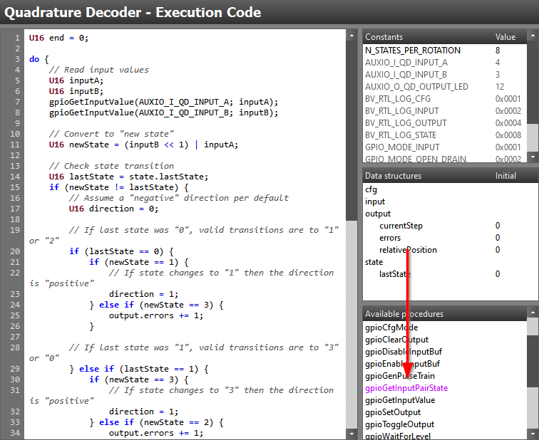
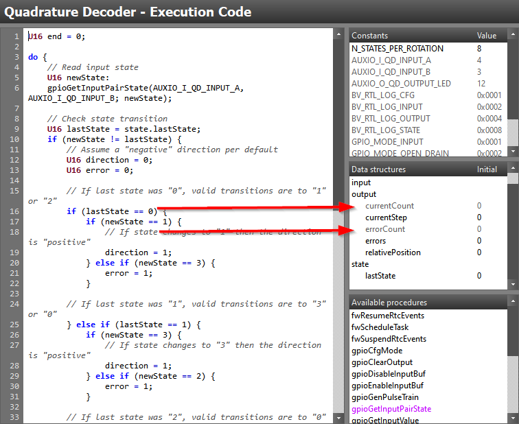
With our procedure file now completed, it is time to save it and see if we can access it from SCS. Before we can access it, we need to restart SCS in order for it to reload the procedure files. After a restart, we find a our new procedure being available in the task code view, highlighted in the color pink (all custom procedures will be highlighted in pink) as in the picture below.
Task 4 – Quadrature Decoder Implementation, Take Two
Let us put our new procedure to the test by swapping out the "read section" of the execution code from our initial application from Task 2:
U16 end = 0;

do {
    // Read input state
    U16 newState:
    gpioGetInputPairState(AUXIO_I_QD_INPUT_A, AUXIO_I_QD_INPUT_B; newState);

    // Check state transition
    U16 lastState = state.lastState;
    if (newState != lastState) {
        // Assume a "negative" direction per default
        U16 direction = 0;

        // If last state was "0", valid transitions are to "1" or "2"
        if (lastState == 0) {
            if (newState == 1) {
                // If state changes to "1" then the direction is "positive"
                direction = 1;
            } else if (newState == 3) {
                output.errors += 1;
            }

        // If last state was "1", valid transitions are to "3" or "0"
        } else if (lastState == 1) {
            if (newState == 3) {
                // If state changes to "3" then the direction is "positive"
                direction = 1;
            } else if (newState == 2) {
                output.errors += 1;
            }

        // If last state was "2", valid transitions are to "0" or "3"
        } else if (lastState == 2) {
            if (newState == 0) {
                // If state changes to "0" then the direction is "positive"
                direction = 1;
            } else if (newState == 1) {
                output.errors += 1;
            }

        // If last state was "3" (as it was not 0-2) , valid transitions are to "2" or "1"
        } else {
            if (newState == 2) {
                // If state changes to "2" then the direction is "positive"
                direction = 1;
            } else if (newState == 0) {
                output.errors += 1;
            }
        }

        // Update output variables accordingly
        if (direction == 1) {
            output.currentStep += 1;
        } else {
            output.currentStep -= 1;
        }

        // Log structures
        rtlLogStructs(BV_RTL_LOG_OUTPUT | BV_RTL_LOG_STATE);
    }

    // Update last state
    state.lastState = newState;

    // Toogle debug LED
    gpioToggleOutput(AUXIO_O_QD_OUTPUT_LED);

    // This loop will never break
} while(end == 0);
Execution Code – Second quadrature decoder solution
Before we have a look at the listing file of our updated application, take a few minutes to verify the application behavior and make sure that it still behaves just like in Task 2.
Looking at the Listing File
It is time to perform a new code generation and have a look at the updated listing file to see how all of this impacted the assembly output.
                ...

                ;?     // Read input state
                ;?     U16 newState:
                ;?     gpioGetInputPairState(AUXIO_I_QD_INPUT_A, AUXIO_I_QD_INPUT_B; newState);
  00d9 ---- 1000                             ld          R1, #0
  00da ---- 34be                             iobtst      #(4 & 0x7), [#(IOP_AIODIO0_GPIODIN + (4 >> 3))]
  00db ---- a601                             biob0       /id0069
  00dc ---- 9201                             or          R1, #1
                /id0069:
  00dd ---- 27be                             iobtst      #(3 & 0x7), [#(IOP_AIODIO0_GPIODIN + (3 >> 3))]
  00de ---- a601                             biob0       /id0070
  00df ---- 9202                             or          R1, #2
                /id0070:
                ;?
                ;?     // Check state transition
                ;?     U16 lastState = state.lastState;

                ...
Listing file output – Resulting code using custom procedure
Looking at the listing file, we can clearly see the assembly code corresponding to that of our new procedure. We can see how all the special procedure file annotations, such as the register access markers, is no more. We also see that our immediate type input parameters has been substituted by the constant value that we pass in to the procedure in our execution code.
Comparing the new assembly with the one from the initial application, it
seems that we managed to shrink the input "sample-to-sample delay" from 11
instructions down to a maximum of 4. As a bonus, we also eliminated the three
instructions needed to create the newState variable. This means that our new
code goes from 25 instructions to get the newState variable, down to a maximum
of 7 instructions. This means our worst case loop instruction count went down
from 57 to 39 which in time means we shaved of roughly 1.5 us from the execution
time!
That is good enough, is it not?
Going from roughly 4.75us down to 3.25us indeed is great, but we can do better!
We have now addressed our sampling delay and at the same time saved 18 instructions. Let us now focus on how we can improve the second part of our code, responsible for the count update. It is time to create our first custom resource!
Coffee Break!
Time to stand up, shake those legs and arms. Go grab a cup of coffee/other brew or take a power nap. It is still a long way to go!
Task 5 – Adding A New Resource
While there are multiple paths to improving the second part of our application loop, many of them not including writing any resources or procedures, we will for the purpose of this training choose to walk the complex path. This means that we will not try to optimize our task code for performance first, we will dive straight into making a new resource and writing some more assembly!
Before diving into adding a new resource to SCS, let us look over what feature set we would like our new resource to incorporate. We would like to add:
- A "Quadrature Decoder" resource: Including a procedures that check and evaluate the new input state and return the status.
- A signed 16-bit data member to count state transitions
- A unsigned 16-bit data member to count number of invalid state transitions states, just like our application does today.
Creating a Resource File
Similar to adding a new procedure file, we can add
a new resource file inside the C:\Users\<WIN_USER>\Documents\Texas Instruments\Sensor Controller Studio\
directory by placing a new file inside the resource_defs sub-folder.
As was the case for procedures, there is DTD file available for resources. This
DTD file is named resource_def.dtd and is found inside the SCS installation
directory under the sub-folder resource_defs.
We start by creating a new quadrature_decoder.red file inside the user local
resource_defs folder and opening it, as well the resource DTD file, up in a
text editor. With both files open, we can now start building up the resource
file following the same methodology as when creating our procedure file.
We start by specify the XML version and document type at the top of the file:
<?xml version="1.0" encoding="ISO-8859-15"?>
<!DOCTYPE resource_def SYSTEM "resource_def.dtd"[]>
quadrature_decoder.red – Common resource file header
Adding the "resource_def" Element
Similar to creating the procedure, we find that the first element to add is the
resource_def element and that the DTD specifies that it need to include
the following child element:
| Element | Used for | Number of occurrences |
|---|---|---|
| desc | Resource description and/or documentation | Once only |
The optional child elements are:
| Element | Used for | Number of occurrences |
|---|---|---|
| example | Resource example documentation | Any number |
| chip_family_migration | Chip migration specific filtering | Zero or once only |
| module_ref | Hardware or software modules used | Any number |
| io_func_ref | Specifies I/O functions used | Any number |
| io_array_size | Multiple instances of the I/O functions | Zero or once only |
| io_usage_count | Number of times the resource can be instantiated | Zero or once only |
| rattr | Attribute associated with the resource | Any number |
| buffer_count | Number of times input or output data are duplicated | Zero or once only |
| asm_code | Assembly code to be inserted when using the resource | Any number |
| driver_code | C source code to be patched into the generated code | Any number |
| conversion | Conversions to be applied to the SCS project once loaded | Any number |
We also see that the resource_def element requires the following attributes:
| Element | Used for |
|---|---|
| chip_family | Specifying supported chip-family(s) |
| name | Defining the resource display name |
| category | Sorting of the resource inside SCS |
| version | Resource version |
Let us add the first element and give it the name Quadrature Decoder, make
it available for all chip families and sort it under the Utilities
resource group:
<?xml version="1.0" encoding="ISO-8859-15"?>
<!DOCTYPE resource_def SYSTEM "resource_def.dtd"[]>
<resource_def chip_family="0,1" name="Quadrature Decoder" category="Utilities" version="1.0.0">
  ...
</resource_def>
quadrature_decoder.red – Added resource_def element
Adding the "desc" Element
The desc child element has the exact same purpose as in the procedure case,
serving as the documentation for the resource which is displayed in for example
the SCS help section. As it is required, let us add a very quick description of
our new resource.
<?xml version="1.0" encoding="ISO-8859-15"?>
<!DOCTYPE resource_def SYSTEM "resource_def.dtd"[]>
<resource_def chip_family="0,1" name="Quadrature Decoder" category="Utilities" version="1.0.0">
  <desc>
    <![CDATA[
      This is a collection of Quadrature Decoder utilities.
    ]]>
  </desc>
  ...
</resource_def>
quadrature_decoder.red – Added the description element
Adding the "rattr" Element
The rattr child element allows us to specify resource specific constants and
data structure members that will be added together with the resource once used
in a project.
Hold on, did we just skip over a bunch of elements?
Yes we did. In order to limit the scope of this training, and due to the expectations on our new resource, we did not need to add the following elements:
- example – We do not need to add examples to the resource documentation
- chip_family_migration – We do not need any special migration documentation
- module_reg – The resource will only provide utility type functionality, there is no hardware/software module dependency.
- event_trigger – The resource does not trigger any special event handler code
- io_func_ref – No I/O is used by our new resource
- io_array_size – No I/O is used by our new resource
io_usage_count – No I/O is used by our new resource
Later we will also skip the following elements:
driver_code – There is no extra C source needed in the generated output
- conversion – No project conversion needed
- enable_resource – No project conversion needed
As mentioned at the start of Task 5, we want the resource to add two variables, one to keep the count and one to count number of errors. Following the description in the DTD files, we add the following to our resource file:
<?xml version="1.0" encoding="ISO-8859-15"?>
<!DOCTYPE resource_def SYSTEM "resource_def.dtd"[]>
<resource_def chip_family="0,1" name="Quadrature Decoder" category="Utilities" version="1.0.0">
  <desc>
    <![CDATA[
      This is a collection of Quadrature Decoder utilities.
    ]]>
  </desc>
  <rattr name="output.currentCount" type="dec" content="struct" scope="task" min="-32768" max="32767">0</rattr>
  <rattr name="output.errorCount" type="dec" content="struct" scope="task" min="0" max="65535">0</rattr>
  ...
</resource_def>
quadrature_decoder.red – Added resource specific data structure members
Looking at the addition to our resource file above, we see that the name
attribute of the rattr elements look a bit odd. This is because the target
data structure is pre-pended to the member name. In practice, this means that
output.currentCount reads "Create a new member inside the output structure
named currentCount".
The next child element in the list is buffer_count but as we do not wish to
use multi-buffering, we will not add this to our resource file.
Adding the "asm_code" Element
The asm_code element allows us to specify assembly code that should be added
to the project when the resource is in use. This element is not always required
but as we in this training will later look into making external assembly
files, we want to add in a convenient assembly alias together with the resource:
<?xml version="1.0" encoding="ISO-8859-15"?>
<!DOCTYPE resource_def SYSTEM "resource_def.dtd"[]>
<resource_def chip_family="0,1" name="Quadrature Decoder" category="Utilities" version="1.0.0">
  <desc>
    <![CDATA[
      This is a collection of Quadrature Decoder utilities.
    ]]>
  </desc>
  <rattr name="output.currentCount" type="dec" content="struct" scope="task" min="-32768" max="32767">0</rattr>
  <rattr name="output.errorCount" type="dec" content="struct" scope="task" min="0" max="65535">0</rattr>
  <asm_code usage="defines">
    <![CDATA[
        .alias  qdTaskName            'A{taskName}'
    ]]>
</asm_code>
</resource_def>
quadrature_decoder.red – Adding task name assembly define
The qdTaskName alias that we just added above can later be used from assembly
to directly access the tasks data structure and members. For example, this alias
could be used to load the value of the currentCount variable by addressing it
directly:
ld R0, [#qdTaskName/output/currentCount]
Accessing task data structure members from assembly
We are now done writing the resource file. Time to see if it shows up inside SCS, like when adding a new procedure, save the file and restart SCS to allow it to load the new resource file. After the SCS restart, we should be able to find the new resource in the list of available task resources:
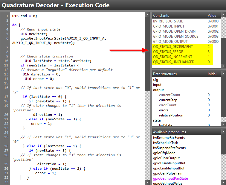
After adding this to our project, we find in the task code view that two new data structures members was indeed added to the project:
Mind the color scheme
Looking closely at the color of the data structure members, we find that the members added explicitly by a resource are colored grey.
Task 6 – External Assembly Dependencies
In Task 3 we wrote all the assembly inside the procedure file. As procedures becomes more complex, it is sometimes more convenient to move the assembly routines into an external assembly file and instead jump to these from the procedure file assembly.
Before we get to writing the external assembly file we will make a quick addition to our resource file.
Revisiting the Resource File
As we want our new procedure to return a status, it would be helpful to have the resource file define assembly and task code constants:
<?xml version="1.0" encoding="ISO-8859-15"?>
<!DOCTYPE resource_def SYSTEM "resource_def.dtd"[]>
<resource_def chip_family="0,1" name="Quadrature Decoder" category="Utilities" version="1.0.0">
  <desc>
    <![CDATA[
      This is a collection of Quadrature Decoder utilities.
    ]]>
  </desc>
  <rattr name="output.currentCount" type="dec" content="struct" scope="task" min="-32768" max="32767">0</rattr>
  <rattr name="output.errorCount" type="dec" content="struct" scope="task" min="0" max="65535">0</rattr>

  <rattr name="QD_STATUS_UNCHANGED"  type="expr" content="const" scope="task" min="0" max="3">0</rattr>
  <rattr name="QD_STATUS_INCREMENT"  type="expr" content="const" scope="task" min="0" max="3">1</rattr>
  <rattr name="QD_STATUS_DECREMENT"  type="expr" content="const" scope="task" min="0" max="3">2</rattr>
  <rattr name="QD_STATUS_ERROR"  type="expr" content="const" scope="task" min="0" max="3">3</rattr>

  <asm_code usage="defines">
    <![CDATA[
        .define QD_STATUS_UNCHANGED   0
        .define QD_STATUS_INCREMENT   1
        .define QD_STATUS_DECREMENT   2
        .define QD_STATUS_ERROR       3
        .alias  qdTaskName            'A{taskName}'
    ]]>
</asm_code>
</resource_def>
quadrature_decoder.red – Adding task code constants and assembly defines
Looking at the updated resource file above, we can see that we added four new assembly define as well as four new task code constants. Save and restart SCS once again, this should add the four constant above to the projects pre-defined constants.
Writing the Assembly
We will start by creating the assembly file inside the proc_def folder just
like in Task 3. Name
the file quadrature_decoder.asm and open it. The complete assembly routine
that we will use is provided below:
; INPUT PARAMETERS:
;     R1 = New state
;
; RETURN PARAMETERS:
;     R1 = Status
;
; CLOBBERS:
;     R0, R1
qdCountUpdate:
        ; OR in new state with our internal state and load the corresponding
        ; LUT entry
        ld      R0, [#qdInternalLastState]  ; Load internal state
        add     R0, #qdDecisionLut          ; Add LUT offset to the combined value
        ld      R0, [R1+R0]                 ; Load the LUT value

        ; Before we can use R0 to jump, we need to wait at least two cycles due
        ; to pipeline hazards, we use this time to update the internal state variable
        lsl     R1, #2                  ; Shift new state with 2 bits
        st      R1, [#qdInternalLastState]  ; Store the shifted state as our new internal state

        ; It is now safe to jump based on the R0 value
        jmp     R0

    ; New state == old state
    /stateUnchanged:
        ; Nothing to do, just return
        ld      R1, #QD_STATUS_UNCHANGED; Set initial return status to "QD_STATUS_UNCHANGED"
        rts                         ; Return from subroutine

    ; State "positive" changed
    /incrementCount:
        ; Increment the resource count variable
        ld      R0, [#qdTaskName/output/currentCount]
        add     R0, #1
        st      R0, [#qdTaskName/output/currentCount]
        ld      R1, #QD_STATUS_INCREMENT ; Set initial return status to "QD_STATUS_INCREMENT"
        rts                              ; Return from subroutine

    ; State "negative" changed
    /decrementCount:
        ; Decrement the resource count variable
        ld      R0, [#qdTaskName/output/currentCount]
        add     R0, #-1
        st      R0, [#qdTaskName/output/currentCount]
        ld      R1, #QD_STATUS_DECREMENT ; Set initial return status to "QD_STATUS_DECREMENT"
        rts                              ; Return from subroutine

    ; An invalid state changed
    /errorState:
        ; Increment the resource error variable
        ld      R0, [#qdTaskName/output/errorCount]
        add     R0, #1
        st      R0, [#qdTaskName/output/errorCount]
        ld      R1, #QD_STATUS_ERROR ; Set initial return status to "QD_STATUS_ERROR"
        rts                              ; Return from subroutine


; INTERNAL DATA VARIABLES

; Data variable to hold the store the internal state
qdInternalLastState:
dw      #(3 << 2) ; Our default state is "3"

; Internal jumping LUT for efficient decision making
qdDecisionLut:
dw      #qdCountUpdate/stateUnchanged ; Old state "0" and new state "0"
dw      #qdCountUpdate/incrementCount ; Old state "0" and new state "1"
dw      #qdCountUpdate/decrementCount ; Old state "0" and new state "2"
dw      #qdCountUpdate/errorState     ; Old state "0" and new state "3"
dw      #qdCountUpdate/decrementCount ; Old state "1" and new state "0"
dw      #qdCountUpdate/stateUnchanged ; Old state "1" and new state "1"
dw      #qdCountUpdate/errorState     ; Old state "1" and new state "2"
dw      #qdCountUpdate/incrementCount ; Old state "1" and new state "3"
dw      #qdCountUpdate/incrementCount ; Old state "2" and new state "0"
dw      #qdCountUpdate/errorState     ; Old state "2" and new state "1"
dw      #qdCountUpdate/stateUnchanged ; Old state "2" and new state "2"
dw      #qdCountUpdate/decrementCount ; Old state "2" and new state "3"
dw      #qdCountUpdate/errorState     ; Old state "3" and new state "0"
dw      #qdCountUpdate/decrementCount ; Old state "3" and new state "1"
dw      #qdCountUpdate/incrementCount ; Old state "3" and new state "2"
dw      #qdCountUpdate/stateUnchanged ; Old state "3" and new state "3"
quadrature_decoder.asm – Complete external assembly
As the goal of the training is not to educate on assembly as a language, we will not look to close at the actual implementation. We will instead look at the methodology used inside the routine where internal data variables and look-up-tables (LUT) are used to speed up execution.
The idea of the assembly routine is to combine the old and new state to a four bit value that we can use as the LUT key to determine how to branch. The routine was partly implemented this way for speed, but also to showcase the concept of keeping internal state inside assembly routines.
External Assembly does not need Annotations
Compared to the assembly code written in the procedure file, the external assembly file do not require the writer to annotate register and label usage.
Creating a New Procedure
With the external assembly in place, we need to add yet another procedure file in order to use our new assembly routine inside the SCS task code. We create a file similar to that of Task 3 but with a few changes.
Name the new procedure file quadrature_decoder.prd and repeat the steps of
Task3. We will give it
a unique procedure name assign Quadrature Decoder as the only referenced
resource. Reading the assembly code presented in the previous step, we see that
register R1 is used as input and output and that R0 is an internal working
register. This means our procedure file needs one input and return parameter
as well as a internal parameter.
Taking this into consideration, we start to put together the following procedure file:
<?xml version="1.0" encoding="ISO-8859-15"?>
<!DOCTYPE proc_def SYSTEM "proc_def.dtd"[]>
<proc_def name="qdUpdateCountFromState" version="1.0.0">
    <desc>
        <![CDATA[
            <p>
            Updates Quadrature Decoder counters based on the input state.
            </p>
        ]]>
    </desc>
    <task_resource_ref>Quadrature Decoder</task_resource_ref>
    <impl chip_family="0,1">
        <param type="reg" name="newState" reg="R1">New state</param>
        <return name="status" reg="R1">Update status</return>
        <internal name="temp0" reg="R0"/>
        <code>
            <![CDATA[
                ...
            ]]>
        </code>
        ...
    </impl>
</proc_def>
quadrature_decoder.prd – Incomplete procedure file
Looking at the procedure implemented above, we see that we now use the reg
attribute of the param, return and internal elements. These register
assignments must correspond to that of the external assembly file routine.
We also note that we now got to use the internal element as we need to make
SCS aware of our new assembly routine clobbering
R0 in addition to R1.
We now get to accessing our external assembly file from inside the procedure
file and this is done by adding an assembly file dependency to the impl
element:
<?xml version="1.0" encoding="ISO-8859-15"?>
<!DOCTYPE proc_def SYSTEM "proc_def.dtd"[]>
<proc_def name="qdUpdateCountFromState" version="1.0.0">
    <desc>
        <![CDATA[
            <p>
            Updates Quadrature Decoder counters based on the input state.
            </p>
        ]]>
    </desc>
    <task_resource_ref>Quadrature Decoder</task_resource_ref>
    <impl chip_family="0,1">
        <param type="reg" name="newState" reg="R1">New state</param>
        <return name="status" reg="R1">Update status</return>
        <internal name="temp0" reg="R0"/>
        <code>
            <![CDATA[
                ...
            ]]>
        </code>
        <asm_file_dep>quadrature_decoder.asm</asm_file_dep>
    </impl>
</proc_def>
quadrature_decoder.prd – Added external assembly dependency
Now that we have included our assembly file as a dependency, we can also jump to the subroutine from the procedure file:
<?xml version="1.0" encoding="ISO-8859-15"?>
<!DOCTYPE proc_def SYSTEM "proc_def.dtd"[]>
<proc_def name="qdUpdateCountFromState" version="1.0.0">
    <desc>
        <![CDATA[
            <p>
            Updates Quadrature Decoder counters based on the input state.
            </p>
        ]]>
    </desc>
    <task_resource_ref>Quadrature Decoder</task_resource_ref>
    <impl chip_family="0,1">
        <param type="reg" name="newState" reg="R1">New state</param>
        <return name="status" reg="R1">Update status</return>
        <internal name="temp0" reg="R0"/>
        <code>
            <![CDATA[
              jsr         qdCountUpdate
            ]]>
        </code>
        <asm_file_dep>quadrature_decoder.asm</asm_file_dep>
    </impl>
</proc_def>
quadrature_decoder.prd – Jumping to external subroutine
Finally, we need to add a few parameter references to our procedure file, this as we need to mark dummy read/write accesses to all of the parameters to avoid compilation errors and unexpected optimization issues. Input variables typically need an initial "get" and a final "set" annotation. Clobbered registers need to be referenced with an initial "set" and final "get" annotation. This gives us the final procedure file:
<?xml version="1.0" encoding="ISO-8859-15"?>
<!DOCTYPE proc_def SYSTEM "proc_def.dtd"[]>
<proc_def name="qdUpdateCountFromState" version="1.0.0">
    <desc>
        <![CDATA[
            <p>
            Updates Quadrature Decoder counters based on the input state.
            </p>
        ]]>
    </desc>
    <task_resource_ref>Quadrature Decoder</task_resource_ref>
    <impl chip_family="0,1">
        <param type="reg" name="newState" reg="R1">New state</param>
        <return name="status" reg="R1">Update status</return>
        <internal name="temp0" reg="R0"/>
        <code>
            <![CDATA[
              ref         RG{newState}
              ref         RS{status}, RS{temp0}

              jsr         qdCountUpdate

              ref         RG{status}, RG{temp0}
              ref         RS{newState}
            ]]>
        </code>
        <asm_file_dep>quadrature_decoder.asm</asm_file_dep>
    </impl>
</proc_def>
quadrature_decoder.prd – Added procedure annotations
We can once more save all our work and restart SCS to find our new
qdUpdateCountFromState() procedure being available inside the task code view.
Task 7 – Quadrature Decoder Implementation, Take Three
Like in Task 4 we update our application code and again to check how this improves our execution speed:
U16 end = 0;

do {
    // Read input state
    U16 newState;
    gpioGetInputPairState(AUXIO_I_QD_INPUT_A, AUXIO_I_QD_INPUT_B; newState);

    // Update Quadrature Decoder count
    U16 returnStatus;
    qdUpdateCountFromState(newState; returnStatus);

    // Only log structures if state change
    if (returnStatus != 0) {
        rtlLogStructs(BV_RTL_LOG_OUTPUT | BV_RTL_LOG_STATE);
    }

    // Toogle debug LED
    gpioToggleOutput(AUXIO_O_QD_OUTPUT_LED);

    // This loop will never break
} while(end == 0);
Execution Code – Third quadrature decoder solution
At a first glance, we see that our new procedure made our task code a lot smaller. Like in Task 4, make sure that the application still behave as expected before moving on to looking at the impact the last few changes did to the final assembly code. Note that unlike the previous versions, this one keeps the "last state" internal which means this can't be monitored during testing. Comparation can thus only be done on the actual result, step and error count.
Looking at the Listing File
Let us once more perform a code generation and look at the updated listing file:
              /id0073:
              ;?     // Read input state
              ;?     U16 newState;
              ;?     gpioGetInputPairState(AUXIO_I_QD_INPUT_A, AUXIO_I_QD_INPUT_B; newState);
00db ---- 1000                             ld          R1, #0
00dc ---- 34be                             iobtst      #(4 & 0x7), [#(IOP_AIODIO0_GPIODIN + (4 >> 3))]
00dd ---- a601                             biob0       /id0074
00de ---- 9201                             or          R1, #1
              /id0074:
00df ---- 27be                             iobtst      #(3 & 0x7), [#(IOP_AIODIO0_GPIODIN + (3 >> 3))]
00e0 ---- a601                             biob0       /id0075
00e1 ---- 9202                             or          R1, #2
              /id0075:
              ;?
              ;?     // Update Quadrature Decoder count
              ;?     U16 returnStatus;
              ;?     qdUpdateCountFromState(newState; returnStatus);
00e2 ---- 14f7                             jsr         qdCountUpdate
              ;?
              ;?     // Only log structures if state change
              ;?     if (returnStatus != 0) {
00e3 ---- 9a00                             cmp         R1, #0
00e4 ---- b604                             beq         /id0080
              ;?         rtlLogStructs(BV_RTL_LOG_OUTPUT | BV_RTL_LOG_STATE);
00e5 ---- 000c                                 ld          R0, #12
00e6 ---- 18ab                                 ld          R1, [#(pRtlTaskLogMaskTable + 0)]
00e7 ---- 8d01                                 and         R0, R1
00e8 ---- 0caa                                 st          R0, [#(pRtlTaskLogReqTable + 0)]
              ;?     }
              /id0080:
              ;?
              ;?     // Toogle debug LED
              ;?     gpioToggleOutput(AUXIO_O_QD_OUTPUT_LED);
00e9 ---- 74cb                             iobset      #(12 & 0x7), [#(IOP_AIODIO0_GPIODOUTTGL + (12 >> 3))]
              ;?
              ;?     // This loop will never break
              ;? } while(end == 0);
00ea ---- aa00                         cmp         R2, #0
00eb ---- b6ef                         beq         /id0073

...

; INPUT PARAMETERS:
;     R1 = New state
;
; RETURN PARAMETERS:
;     R1 = Status
;
; CLOBBERS:
;     R0, R1
qdCountUpdate:
                      ; OR in new state with our internal state and load the corresponding
                      ; LUT entry
00f7 ---- 090f         ld      R0, [#qdInternalLastState]  ; Load internal state
00f8 8601 8810         add     R0, #qdDecisionLut          ; Add LUT offset to the combined value
00fa ---- 8f19         ld      R0, [R1+R0]                 ; Load the LUT value

                      ; Before we can use R0 to jump, we need to wait at least two cycles due
                      ; to pipeline hazards, we use this time to update the internal state variable
00fb ---- 9da2         lsl     R1, #2                  ; Shift new state with 2 bits
00fc ---- 1d0f         st      R1, [#qdInternalLastState]  ; Store the shifted state as our new internal state

                      ; It is now safe to jump based on the R0 value
00fd ---- 8db7         jmp     R0

                  ; New state == old state
                  /stateUnchanged:
                      ; Nothing to do, just return
00fe ---- 1000         ld      R1, #QD_STATUS_UNCHANGED; Set initial return status to "QD_STATUS_UNCHANGED"
00ff ---- adb7         rts                         ; Return from subroutine

                  ; State "positive" changed
                  /incrementCount:
                      ; Increment the resource count variable
0100 ---- 08b8         ld      R0, [#qdTaskName/output/currentCount]
0101 ---- 8801         add     R0, #1
0102 ---- 0cb8         st      R0, [#qdTaskName/output/currentCount]
0103 ---- 1001         ld      R1, #QD_STATUS_INCREMENT ; Set initial return status to "QD_STATUS_INCREMENT"
0104 ---- adb7         rts                              ; Return from subroutine

...
Listing file output – Take 3, resulting assembly
By counting the instructions that makes up the worst case execution path, we see that our new resource/procedure enabled us to save an additional 10 instructions in our sample loop. The new maximum loop instruction count is 29 which means the new sample loop time is roughly 2.41 us!
Well now we are for sure done (I can't take it anymore)
Let us start by patting our own backs for sticking with the training to the end!
While our efforts did result in us bringing the sampling time to just about 2.41 us, the last half if it was actually not really required. Instead of making a custom resource and procedure to efficiently count our state transitions, we could have achieved the same result by just writing smart task code. If you are interested in how such a solution would look, please continue on with the bonus tasks.
We have now gone over the very basics of how to create your own procedures and resources and how to use these together with the Sensor Controller and SCS. There is much more to this then what is covered in this training and it is recommended to use the DTD file documentation as well as the pre-existing resources and procedures as documentation/templates when needed.
Task 8 – BONUS: Writing Smart Task Code
While we in our third attempt tried to improve on our application performance by creating a new resource and yet another procedure, this was actually not required. By introducing a cleaver LUT to our task code we could write code that is as good in terms of performance.
The basic idea behind the new example is to use a 4 entry LUT to check which
state transition occurred. There is one LUT entry per possible state and the LUT
value is then shifted right based on new state to retrieve the nibble that
indicates count direction or error transition. The relevant code blocks is found
below, starting with the Initialization Code.
// Find the initial quadrature state
gpioGetInputPairState(AUXIO_I_A, AUXIO_I_B; state.initQuadratureState);

// Create the quadrature state machine look-up table
// Valid state transitions are 00 - 01 - 11 - 10 - 00 (2-bit gray-coded wheel).
// There is one 16-bit word for each previous quadrature state, with Index n = 0,1,2,3.
// The new rotation state selects a nibble in the previous rotation state (1st, 2nd, 3rd or 4th nibble in LUT Fsm[]
// This nibble specifies which counter to update:
//     - 0x0 = no counter update
//     - 0x1 = decrement rotation count
//     - 0x2 = increment rotation count
//     - 0x4 = increment error count

// This LUT [0-3] counts every edge or quarter turn
state.pQuadratureFsm[0] = 0x4120; // Decrement: 00->10, Increment: 00->01, Error: 00->11
state.pQuadratureFsm[1] = 0x2401; // Decrement: 01->00, Increment: 01->11, Error: 01->10
state.pQuadratureFsm[2] = 0x1042; // Decrement: 10->11, Increment: 10->00, Error: 10->01
state.pQuadratureFsm[3] = 0x0214; // Decrement: 11->01, Increment: 11->10, Error: 11->00

fwScheduleTask(1);
Initialization Code – Quadrature Decoder, alternative version
As can be seen in the Initialization Code above, this implementation requires
a pQuadratureFsm array to be added to the project. This array makes up the
application LUT and is populated once inside the Initialization Code.
Creating arrays
A quick reminder on how to create a array inside SCS, you first need to create a constant defining the size of the array!
U16 end = 0;

// Using local variables to minimize number of load instructions
U16 stepCount = output.stepCount;
U16 errorCount = output.errorCount;

// Get the initial quadrature state
U16 quadratureState = state.initState;

do {
    // Find the quadrature FSM entry to be used for this iteration, based on the previous iteration
    U16 n = quadratureState;
    U16 quadratureFsmEntry = state.pQuadratureFsm[n];

    // Read input state
    gpioGetInputPairState(AUXIO_I_QD_INPUT_A, AUXIO_I_QD_INPUT_B; quadratureState);

    // Find the update action (0, 1, 2 or 4) for edge or error counter
    // The new quadrature state selects a nibble (= the update action) in the selected FSM entry
    U16 bvQuadratureUpdate = (quadratureFsmEntry >> (quadratureState << 2)) & 0xF;

    // Count down?
    if (bvQuadratureUpdate == 0x1) {

        // Decrement edge counter low part
        stepCount -= 1;
        output.stepCount = stepCount;

        // Log change
        rtlLogStructs(BV_RTL_LOG_OUTPUT | BV_RTL_LOG_STATE);
    // Count up?
    } else if (bvQuadratureUpdate == 0x2) {

        // Increment edge counter low part
        stepCount += 1;
        output.stepCount = stepCount;

        // Log change
        rtlLogStructs(BV_RTL_LOG_OUTPUT | BV_RTL_LOG_STATE);
    // Error?
    } else if (bvQuadratureUpdate == 0x4) {

        // Increment error counter low part
        errorCount += 1;
        output.errorCount = errorCount;

        // Log change
        rtlLogStructs(BV_RTL_LOG_OUTPUT | BV_RTL_LOG_STATE);
    }

    // Toogle debug LED
    gpioToggleOutput(AUXIO_O_QD_OUTPUT_LED);

    // This loop will never break
} while(end == 0);
Execution Code – Quadrature Decoder, alternative version
In the Execution Code above, we see that we first load the LUT value based on
the last state (quadratureState). We the read the next state and modify
the LUT value that previously read out.
Once the modified LUT value is obtained, we check the resulting value to determine the action we need to take. Looking at the resulting assembly code we get the following, worst case, execution path:
;? do {
              /id0076:
              ;?     // Find the quadrature FSM entry to be used for this iteration, based on the previous iteration
              ;?     U16 n = quadratureState;
              ;?     U16 quadratureFsmEntry = state.pQuadratureFsm[n];
00eb ---- 40bb                             ld          R4, #(quadratureDecoder/state/pQuadratureFsm + 0)
00ec ---- cf1c                             ld          R4, [R4+R0]
              ;?
              ;?     // Read input state
              ;?     gpioGetInputPairState(AUXIO_I_QD_INPUT_A, AUXIO_I_QD_INPUT_B; quadratureState);
00ed ---- 0000                             ld          R0, #0
00ee ---- 34be                             iobtst      #(4 & 0x7), [#(IOP_AIODIO0_GPIODIN + (4 >> 3))]
00ef ---- a601                             biob0       /id0080
00f0 ---- 8201                             or          R0, #1
              /id0080:
00f1 ---- 27be                             iobtst      #(3 & 0x7), [#(IOP_AIODIO0_GPIODIN + (3 >> 3))]
00f2 ---- a601                             biob0       /id0081
00f3 ---- 8202                             or          R0, #2
              /id0081:
              ;?
              ;?     // Find the update action (0, 1, 2 or 4) for edge or error counter
              ;?     // The new quadrature state selects a nibble (= the update action) in the selected FSM entry
              ;?     U16 bvQuadratureUpdate = (quadratureFsmEntry >> (quadratureState << 2)) & 0xF;
00f4 ---- dd40                             ld          R5, R0
00f5 ---- dda2                             lsl         R5, #2
00f6 ---- cd8d                             lsr         R4, R5
00f7 ---- c00f                             and         R4, #15
              ;?
              ;?     // Count down?
              ;?     if (bvQuadratureUpdate == 0x1) {
00f8 ---- ca01                             cmp         R4, #1
00f9 ---- be07                             bneq        /id0085

...

              ;?     // Count up?
              ;?     } else if (bvQuadratureUpdate == 0x2) {
...
              /id0085:
0101 ---- ca02                             cmp         R4, #2
0102 ---- be07                             bneq        /id0092

...

              ;?     // Error?
              ;?     } else if (bvQuadratureUpdate == 0x4) {
...
              /id0092:
010a ---- ca04                             cmp         R4, #4
010b ---- be06                             bneq        /id0099
              ;?
              ;?         // Increment error counter low part
              ;?         errorCount += 1;
010c ---- b801                                 add         R3, #1
              ;?         output.errorCount = errorCount;
010d ---- 3cb8                                 st          R3, [#quadratureDecoder/output/errorCount]
              ;?
              ;?         // Log change
              ;?         rtlLogStructs(BV_RTL_LOG_OUTPUT | BV_RTL_LOG_STATE);
010e ---- 400c                                 ld          R4, #12
010f ---- 58ab                                 ld          R5, [#(pRtlTaskLogMaskTable + 0)]
0110 ---- cd05                                 and         R4, R5
0111 ---- 4caa                                 st          R4, [#(pRtlTaskLogReqTable + 0)]
              ;?     }
              /id0099:
              /id0094:
              /id0087:
              ;?
              ;?     // Toogle debug LED
              ;?     gpioToggleOutput(AUXIO_O_QD_OUTPUT_LED);
0112 ---- 74cb                             iobset      #(12 & 0x7), [#(IOP_AIODIO0_GPIODOUTTGL + (12 >> 3))]
              ;?
              ;?     // This loop will never break
              ;? } while(end == 0);
0113 ---- 9a00                         cmp         R1, #0
0114 ---- b6d6                         beq         /id0076
Final Assembly – Quadrature Decoder, alternative version assembly
Counting the number instructions, we end up at 28 instructions in total, one instuction less then in Task 7. This means that this "Task Code" based solution was more efficient then the custom procedure we created for counting our state transitions.
Both more efficient and felxible? WOW!
Not only did we improve (by very litte) the performance by instead writing it in task code, we also gained a lot of flexibility doing so! Furthermore, the task code version, being written mainly in in C-like code, is easier to understand and to maintain.
Assume the requirements change and we suddenly need out output counters to be 32-bit? Well we can just extend on the code in a simple manner without having to go over the effort of changing/re-writing our custom procedures. We also got much better control each individual step which means we could debug behavior much easier.
We have now reached the ultimate end of this training. Good luck in your future work with the Sensor Controller and as always, further technical questions can be asked in the Texas Instruments E2E forum.
Technical Reference Manuals
For your convenience, links to the device specific technical reference manuals are provided: