Introduction
In this workshop we will construct a simple application that continually reads an ADC channel and toggles an LED on or off depending on whether or not our ADC reading exceeds a custom threshold. We will create a simple PC-side graphical user interface (GUI) that complements our application code.
To do this, we will use a nifty tool called GUI Composer. GUI Composer is a browser-based utility for creating PC-side graphical interfaces for interacting with your hardware. GUI Composer supports several interfaces today, including Serial/UART, JTAG/XDS, or MQTT (for IoT applications).
For this demo, we will use the JTAG/XDS interface. We will visualize our latest ADC readings in an analog gauge & will add a horizontal slider for dynamically setting the threshold that triggers the LED to turn on/off.
Here's what we'll learn:
- Get introduced to TI's GUI Composer
- Create a simple analog gauge for visualizing ADC values
- Create a horizontal slider to dynamically set a threshold
- Add an "LED" indicator to the GUI that mirrors the physical LED on our LaunchPad kit
SysConfig support
This SimpleLink Academy lab supports both devices with and without SysConfig. Please note instructions are sometimes divided in two in the following way.
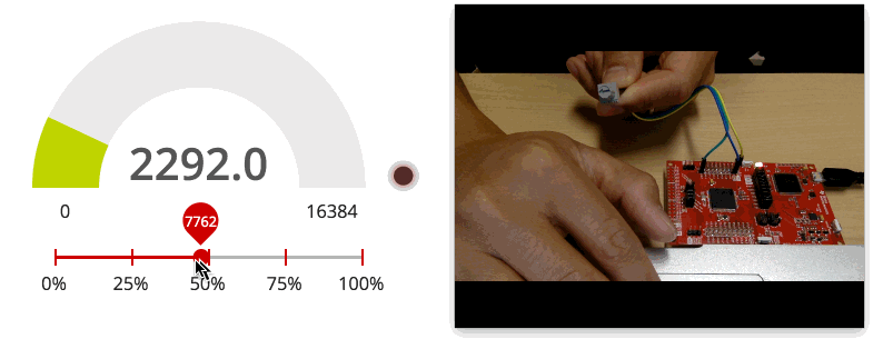
Preview of the GUI we're making:
What is GUI Composer
GUI Composer is a browser-based "What you see is what you get" (WYSIWYG) tool for developing PC-side HTML-based graphical user interfaces (GUIs) that can complement your embedded project/application. With this tool users will be able to drag & drop various GUI elements into a sandbox to build their interface. These tools include gauges, dials, sliders, line charts & more.
Features:
- Allows you to build HTML-based GUIs graphically (simple drag & drop interface)
- Supports communication with the target device via USB (serial I/O), XDS Debug Port or the Internet (MQTT / IoT)
- Wide variety of components to choose from, including graphs, gauges, dials, buttons, menus, meters, and many more
- Components configured via easy-to-use properties
- Full JavaScript editor provided for advanced users
What interfaces does GUI Composer support?
GUI Composer supports various data transport interfaces. The following are supported:
- Serial/UART
- JTAG/XDS Debug interface (This is the interface we will use for this training)
- MQTT (Internet of Things)
Prerequisites
Required material (you'll need the project created in this lab)
Software for desktop development
- This tutorial can be done 100% with a web browser in CCS Cloud
- The exercises can also be completed using desktop/offline tools as well. If you want to run the exercises offline, you will need to download & install the following:
- CCS (refer to the SimpleLink SDK's Release Notes for recommended version)
- SimpleLink SDK for your given LaunchPad:
- We will make small modifications to an existing example & will use GUI Composer to build a simple graphical interface for use with our application
Hardware requirements
A SimpleLink MCU LaunchPad Development Kit:
Recommended Reading
- GUI Composer User's Guide: https://dev.ti.com/gc/designer/help/UsersGuide/index.html
Task 1 - Setting up code example for GUI Composer
Please complete the TI Drivers Project Zero lab. We will use the same "empty" project in this lab.
In this exercise, we want to build a simple GUI that does the following things:
- Visualize our latest ADC readings using an analog gauge
- Get an "LED" notification when we are above/below a threshold
Feature a slider that allows us to modify the threshold for the LED alert
The project will have the following global variables that GUI Composer can use:
adcValueWe will eventually bind this global variable to an analog gauge in the GUI to visualize our latest readings.
thresholdWe will eventually bind this global variable with a slider to enable the threshold to be altered via the GUI.
triggerWe can use this global variable to feed the LED indicator in the GUI we are about to build.
/* global variableS FOR GUI COMPOSER */
uint16_t adcValue = 0;
uint16_t threshold = 100;
uint16_t trigger = 0;
/*
* ======== mainThread ========
*/
void *mainThread(void *arg0)
{
/* ~10 loops/second */
uint32_t time = 100000; // update ~10/second
/* Call driver init functions */
GPIO_init();
ADC_init();
// I2C_init();
// SPI_init();
// UART_init();
// Watchdog_init();
/* Open ADC Driver */
ADC_Handle adc;
ADC_Params params;
ADC_Params_init(¶ms);
adc = ADC_open(CONFIG_ADC_0, ¶ms);
if (adc == NULL) {
// Error initializing ADC channel 0
while (1);
}
while (1) {
int_fast16_t res;
res = ADC_convert(adc, &adcValue);
if (res == ADC_STATUS_SUCCESS) {
if(adcValue >= threshold) {
GPIO_write(CONFIG_GPIO_LED_0, CONFIG_GPIO_LED_ON);
trigger = 1;
} else{
GPIO_write(CONFIG_GPIO_LED_0, CONFIG_GPIO_LED_OFF);
trigger = 0;
}
}
usleep(time);
}
}
mainthread in empty.c
Setup ADC with classic TI Drivers
/* global variableS FOR GUI COMPOSER */
uint16_t adcValue = 0;
uint16_t threshold = 100;
uint16_t trigger = 0;
/*
* ======== mainThread ========
*/
void *mainThread(void *arg0)
{
/* ~10 loops/second */
uint32_t time = 100000; // update ~10/second
/* Call driver init functions */
GPIO_init();
ADC_init();
// I2C_init();
// SDSPI_init();
// SPI_init();
// UART_init();
// Watchdog_init();
/* Open ADC Driver */
ADC_Handle adc;
ADC_Params params;
ADC_Params_init(¶ms);
adc = ADC_open(Board_ADC0, ¶ms);
if (adc == NULL) {
// Error initializing ADC channel 0
while (1);
}
/* Open Display Driver */
Display_Handle displayHandle;
Display_Params displayParams;
Display_Params_init(&displayParams);
displayHandle = Display_open(Display_Type_UART, NULL);
while (1) {
int_fast16_t res;
res = ADC_convert(adc, &adcValue);
if (res == ADC_STATUS_SUCCESS) {
Display_printf(displayHandle, 1, 0, "ADC Reading %d", adcValue);
if(adcValue >= threshold){
GPIO_write(Board_GPIO_LED0, Board_GPIO_LED_ON);
trigger = 1;
} else{
GPIO_write(Board_GPIO_LED0, Board_GPIO_LED_OFF);
trigger = 0;
}
}
usleep(time);
}
}
mainThread and globals in empty.c
At a high level, the device will read the ADC value every 10 ms to adcValue.
Then, if adcValue >= threshold, trigger will be set (and LED will be turned on).
Otherwise, trigger will be cleared (and LED will be turned off).
Let's compile our code to generate a .out file.
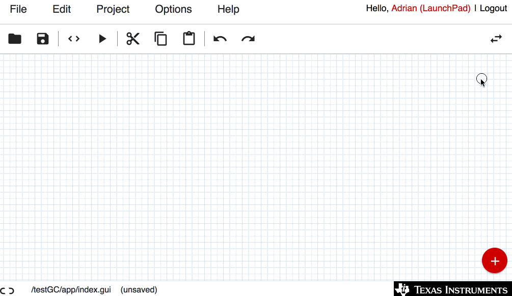
Task 2 - Creating our first GUI!
1. Launch GUI Composer & Create new GUI project!
Now that we have our .out file, we can launch GUI Composer by navigating to https://dev.ti.com/gc
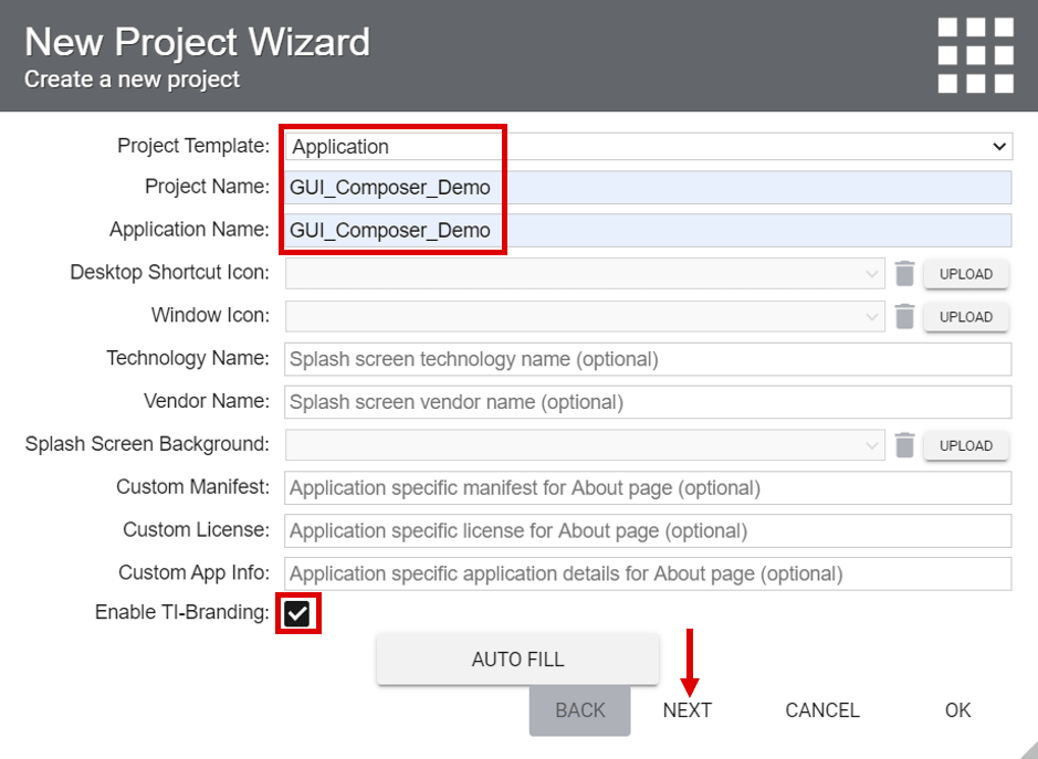
Select "CREATE A NEW PROJECT" to launch the "New Project Wizard."
Let's use the following parameters:
- Project Template: Application
- Project Name: GUI_Composer_Demo
- Application Name: GUI_Composer_Demo
- Enable TI-Branding: [Check]
Then, press NEXT >>
2. The Target programming window
We need to tell GUI Composer which device we are using as well as upload the .out file of our firmware. This will allow GUI Composer to unintrusively read/modify global variables without any additional code required in our firmware.
Start by clicking "ADD".
Select the device you are using
In the development of this tutorial, we used the MSP-EXP432P401R LaunchPad, so we will select MSP432P401R. Be sure to select the device you are developing with. After selecting your device the Connection field should automatically be populated. You can also find the connection mechanism your launchpad uses on its product page or within its provided documentation.
Upload your .out file
Click the upload button & navigate to the .out file inside your local CCS project or to the .out file that you downloaded from CCS Cloud.
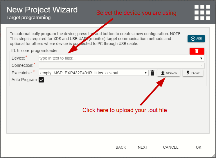
Leave Auto Program checked and press NEXT.
3. The Target communication window
In this window we specify how we will extract data from our target.
Select a transport mechanism
Create a new transport mechanism by pressing the "Add" button. The XDS transport option is available on Cortex-based MCU's and C2000 devices. As we have been using the MSP-EXP432P401R in this workshop, we will select XDS.
Select a data representation scheme
The target data representation scheme (a.k.a. Available Model) we will use is "Program". Ensure this is selected, then click the "Add" button next to the selection. On the resulting screen under Program Model there should only be one option for Program Loader ID - "ti_core_programloader". Finally, click "OK" to exit the wizard and create the project.
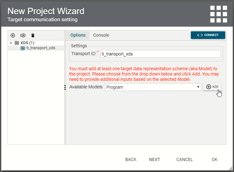
Please see the "Interacting with a Target Device" section of the GUI Composer User's Guide for an explanation of the different target communication options.
4. Adding elements to your GUI
At this point, we should have a blank window to start developing our GUI. We can search the palette of available GUI elements by opening the component palette on the left-hand side of the editor.
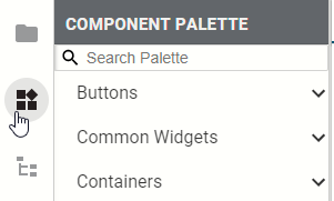
For this demo, we need 3 different elements:
- Dials & Gauges > Analog Meter (for our ADC readings)
- Common Widgets > Horizontal Slider (for modifying our threshold)
- Status Indicators > LED (to indicate if ADC reading is above/below threshold)
Search for these items in the GUI palette & drag them into the GUI editor window. The editor may look a bit different from what is presented below. You should end up with the following:
5. Editing GUI elements with Properties & Styles panel
Each GUI element can be modified & edited using the Properties & Styles panel. Click on the GUI element you want to modify, then simply edit the parameters in the side configuration pane.
For this tutorial, we need to make a few small adjustments
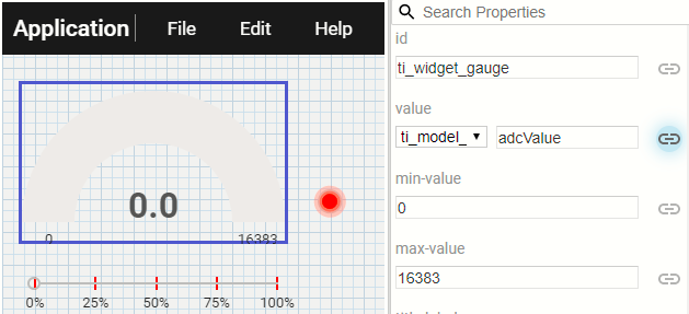
Analog meter
- Change the max-value to the maximum digital number your device's ADC resolution can support. The MSP432P401R device we are using has a 14-bit Analog to Digital Converter, which can give us 2^14 unique readings. So we'll put 16,383 as our max-value.
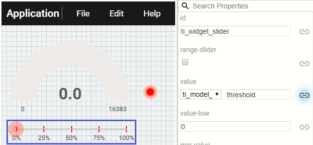
Horizontal slider
- We want to change the labels here to reflect percentage, so let's change the "labels" parameter to: 0%, 25%, 50%, 75%, 100%
- We also need to change the max-value of the slider to match that of the analog meter. In the case of a 14-bit ADC, we will change it to 16,383.
LED
- If we wanted to, we can change the LED color, but we'll go ahead and leave ours red.
6. Binding global variables with GUI widgets
Now that our GUI elements are configured, we can go ahead & bind the global variables to them. To do this, we will again modify the Properties pane for each widget.
Binding Analog meter
Click the analog meter widget to make it "active." Click the "bind" icon next to the "value" field. This will introduce a drop down menu that is pre-set for "ti_model_program." Leave that as-is. In the empty text field to the right, we will type the name of the global variable that we want to bind. In this case, we want to bind the global variable adcValue
Binding Horizontal slider
Click the horizontal slider widget to make it "active." Click the "bind" icon next to the "value" field. Again, leave the "ti_model_program" drop down as-is & type in the global variable we want to bind to the horizontal slider. In this case, we want to bind the global variable threshold
Binding LED indicator
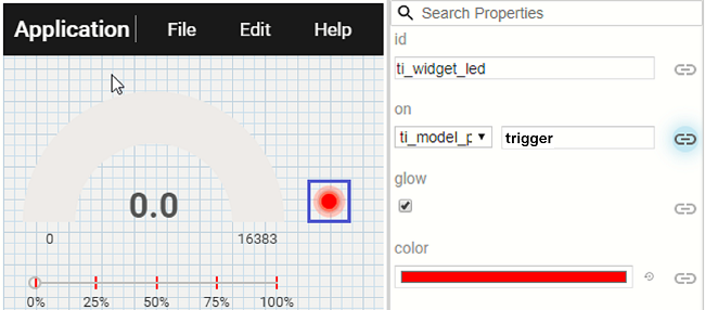
Click the LED indicator widget to make it "active." Click the "bind" icon next to the "on" field. Again, leave the "ti_model_program" drop down as-is & type in the global variable we want to bind to the LED indicator. In this case, we want to bind the global variable trigger
7. Let's run our GUI!
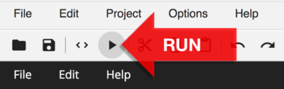
And that's it! Now that we've successfully built our GUI, we can go ahead and run our GUI by clicking the "play" button.
This will open up your GUI in a new tab. At this point, your GUI will start to connect to your LaunchPad, which is running the same firmware that we uploaded into GUI Composer.
At this time, you should see the analog meter updating appropriately. You can also slide the horizontal slider to change the target threshold. Lastly, the LED indicator in the GUI should match the status of the LED found on your LaunchPad.
8. Exporting your GUI/app
Once you're happy with your GUI, you GUI Composer can export your GUI as a standalone application. You can export your GUI by clicking on File > Export > as Stand-Alone App
This will generate a zip file of your GUI, which can now run standalone.
This work is licensed under a Creative Commons Attribution-NonCommercial-NoDerivatives 4.0 International License.