Bluetooth® Low Energy Connections with basic_ble example#
Texas Instruments
2 - 3 hours read
Introduction#
In this module we will learn about Bluetooth® low energy (LE) connections. How is a Blutooth LE connection formed? What information needs to be shared by two devices in order for them to stay connected? How can Bluetooth LE connections be updated? This tutorial will give you an overview of how to set up Bluetooth LE connections suited to your needs.
In this lab we will be working with basic_ble and BTool.
Basics about Bluetooth LE connections will be provided. The first task, will consist of building a connection with basic_ble on the peripheral device.
The second one as SimpleLink CC2340R5 LaunchPad as a central device together with the program BTool.
Then we will discuss about connection parameters and how to update them, from the Central and Peripheral side, respectively.
The two last section will consist in end a connection with a specific function and to customize your project by blinking a LED at each connection event.
This tutorial will take about two hours to complete and requires basic embedded programming skills (see the Prerequisites section for details).
Prerequisites#
Hardware#
2 SimpleLink CC2340R5 LaunchPad Targets
2 SimpleLink LaunchPad XDS110 Debugger
USB cable
SmartPhone or Tablet with a GATT Table viewer application installed (such as TI SimpleLink Connect app)
Software#
Code Composer Studio version 12.3 and newer or IAR 9.32.1 installed with support for CC23xx devices.
SIMPLELINK-LOWPOWER-F3-SDK Software Development Kit (SDK)
BTool (located in the
tools\ble5stackdirectory of the SimpleLink™ Device SDK)Bluetooth LE Client app, such as TI SimpleLink™ Connect app
Note
Have a look the following lab to have more information on the TI SimpleLink Connect App.
Other SimpleLink Academy Labs#
Completion of BLE Scanning and Advertising
Readings#
SDK User’s Guide You should particularly have a look on the Generic Access Profile (GAP) and Generic Attribute Profile (GATT) sections, it will help you to understand a bit more about the theory behind Bluetooh™ Low Energy protocol.
Agenda#
In this training, we will discuss how to the set up a connection with basic_ble example for custom development.
1. Discuss how a Bluetooth LE connection is formed
2. How to set your peripheral device
3. How to set your central device and start a connection
5. Discuss about connection parameters
6. Discuss about connection interval
7. Discuss about peripheral latency
About Bluetooth LE Connections#
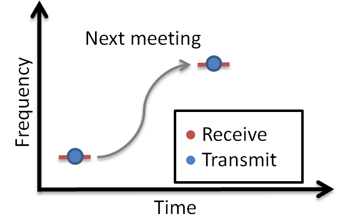
What is a Bluetooth LE connection? A connection implies a link between devices over time. Bluetooth LE is a synchronous radio frequency (RF) protocol, meaning that any transmission between devices must be scheduled. The opposite of this is an asynchronous connection, where the receiving device listens constantly or periodically, and the transmitting device can transmit at any time. A Bluetooth LE connection can thus be perceived as a series of meetings where two devices transmit and receive information at the same time, on the same radio frequency. In order for this to work, the devices must agree on where (that is, on what frequency) and when next to meet. The BLE5-Stack handles connection timing and frequency hopping. The latter will not be further explained in the following text.
Note
If you want to know more about frequency hopping, you can read more about this in the Bluetooth Core Specification Version 5.3 and the TI BLE5-Stack User’s Guide mention in the reading section section above.
Organizing a radio meeting#
A Bluetooth LE connection always consists of two devices. The device that initiates the connection is called the Central. This device also has the final word on timing and frequency hopping. The device that responds to a connection initiation is called the Peripheral.
The Link Layer#
The Link Layer is a part of a Bluetooth Low Energy application that keeps track of whether the device is in a connected state (link) or not. As described in BLE Scanning and Advertising, in order for Bluetooth LE devices to find each other, they must either scan or advertise. A scanning device that has found a connectable advertiser can initiate a connection. The Link Layer states are summed up in the following figure.
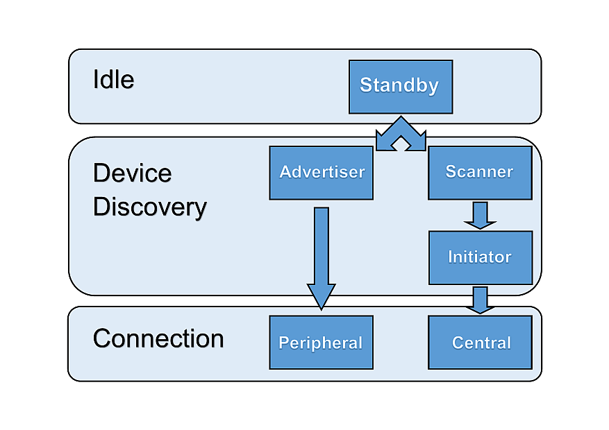
Link layer states#
As explained in BLE Scanning and Advertising, a Bluetooth low energy device has a defined GAP role, which can be one or more of the following: Broadcaster, Observer, Peripheral or Central. As only peripherals and centrals can enter connections, these two will be the focus of this lab. A peripheral is a device with the ability to advertise and to enter a connection allowing to be controlled. A Central is a device that can scan for Bluetooth LE devices and initiate connections. The Central is always the controller of the connection.
Bluetooth LE Connection Life Cycle#
As mentioned, the connection must be initiated by the Central and then accepted by the peripheral device. The connection can be terminated from either the Central or the Peripheral.
The two Bluetooth LE devices are connected as long as they periodically exchange data. The exchange is called a connection event and consists of both devices transmitting and receiving information consecutively. Each connection event starts with the Central transmitting and the Peripheral receiving. Then the Peripheral transmits and the Central receives.
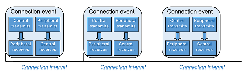
Connection event#
Bluetooth LE Connection Limitations#
Before Bluetooth Core Specification v4.1, a Bluetooth LE peripheral device could connect to only one Central device at a time. Over time, Bluetooth LE has evolved to support more complex topologies, e.g. a star network configuration where one Central device connects to multiple peripheral devices. Or a network where peripheral devices can connect to multiple Central devices, and a device can operate both as a Peripheral and Central role (in different connections) simultaneously without needing to swap roles. Still, Peripherals cannot connect to each other, but instead are limited to connect with Central devices.
The specification does not limit the number of connections. The available memory resources of the device and the time domain determines the maximum number of connections supported. The user can profile the heap used in the project to determine the maximum amount of connections that can be supported.
For more information, see the Debugging Common Heap Issues chapter in the Debugging section of the TI BLE5-Stack User’s Guide in the reading section.
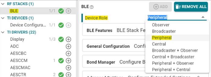
See the
basic_bleexample on thePeripheral + Centralrole for a simultaneous Central/peripheral GAPRole. To modify the role of the example, open yourbasic_ble.syscfgfile, then go toBLE→Device Role. All roles are provided on the samebasic_bleexample.
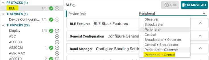
Role on Sysconfig#
See the Topology section ([Vol 1], Part A, Section 3.3.2.1.3) of the Bluetooth Core Specification Version 5.3 for reference.
Task 1 - Set up a connection with basic_ble on the peripheral device#
Here we will consider our Smartphone as a central device. Thus, you need to have Bluetooth LE scanner apps on it, check the software
needed section for more informations.
For our central device to have something to connect to, we need to set up a
Bluetooth LE peripheral device.
Flash one of your SimpleLink™ CC2340R5 Modular LaunchPad™ with basic_ble in a Peripheral role
(follow the Role on Sysconfig picture to know how to change the configuration).
If you need help, follow the instructions in the Quick start guide section located in the reading section.
If you want to check that your peripheral device is advertising, you can use your phone, using a Bluetooth LE Client app.
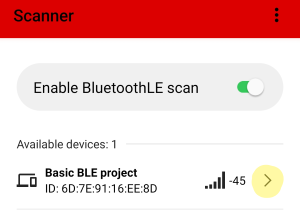
Scanning view on TI SimpleLink™ Connect app#
Hint
Now we have a peripheral that our central device can connect to. Let’s proceed!
Acquire an other device SimpleLink CC2340R5 LaunchPad which play the central role in the connection.
Flash the host_test example from your SIMPLELINK-LOWPOWER-F3-SDK on one device.
Flash the other SimpleLink CC2340R5 LaunchPad with the basic_ble example in a Peripheral role.
Hint
To change the role on basic_ble, open your basic_ble.syscfg file, BLE → Device Role. All roles are provided on the same basic_ble example.
Change the role on Sysconfig#
Open BTool
BTool is a tool bundled with the SimpleLink SDK, found under
<SDK_INSTALL_DIR>\tools\ble5stack\btool. In order to use it,
your computer must be connected to a LaunchPad running the host_test
example project. In this module we will use BTool to control a Bluetooth LE
central, but it can be used for other situations as well. This means that not
all commands found in BTool are suitable or permitted.
Open Run_BTool.bat in <SDK_INSTALL_DIR>\tools\ble5stack\btool. Then click on the Device menu and New Device, the pop up window below shoul appears.
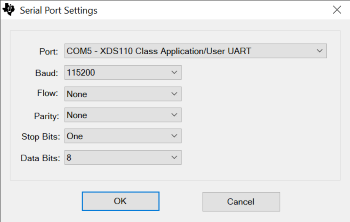
Connection with BTool#
You will be prompted for the COM port of the device. You can find this by opening the Windows device Manager. Right click on This PC → More → Properties, device Manager is found on the menu to the left. Look for the port called XDS110 Class Application/User UART.
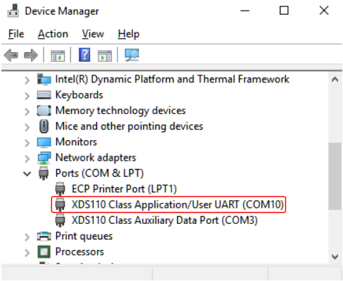
Find device COM port#
If everything went well, BTool will start printing green and blue events. (If you’re seeing yellow or red events, please make sure you found the correct COM port and that the device is not paused by a debug session in CCS. You may also need to hit the LaunchPad reset button before connecting to BTool.)
If you scroll all the way to the top of the BTool log, you can see that the device has been initialized as a Central by GAP.
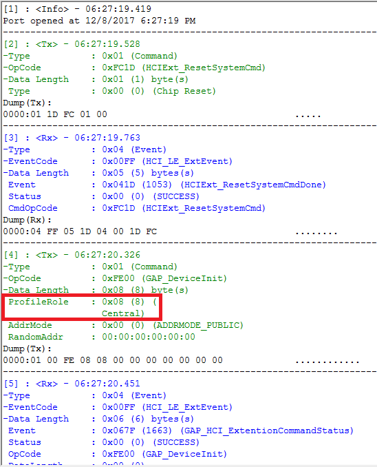
GAP device init#
To the left BTool displays information about the host device. This is also where information about any active connections will be displayed. In the center BTool prints out a log of all commands and events. To the right, some actions are displayed.
When the user sends a command, this is printed in green. These command log
entries start with <Tx> as they are transmitted from BTool to the
device running Host Test. Events received from the LaunchPad running Host Test
are printed in blue and start with <Rx>. For each command sent, BTool
will receive one GAP_HCI_ExtentionCommandStatus event to indicate that the
command was received.
Once the image below is openned, click on the Scan button, it will takes few second to the central to scan all the advertisements around. Then open the combo box Slave BDA and search for your peripheral MAC Address. Once you find it, click on the Establish button, you should create your connection between both devices!
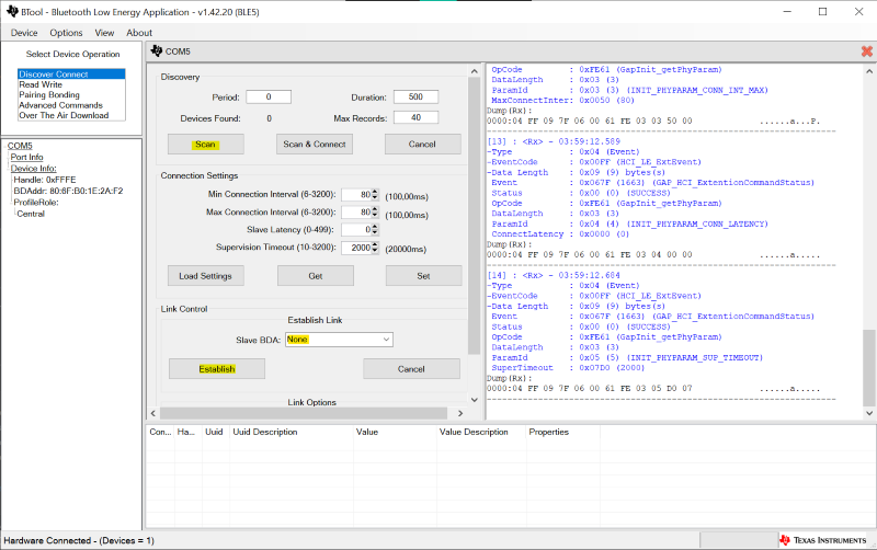
How to establish a connection with BTool#
Hint
Now we have a peripheral that our central device can connect to. Let’s proceed!
What Happens on the Peripheral Side?
By default, basic_ble advertises with connectable undirected advertisements.
This is defined through SysConfig in BLE → Broadcaster Configuration →
Advertisement Set X → Advertisement Parameters X
in the Legacy Event Properties Options field.
You can read more about advertising properties in BLE Scanning and Advertising.
When using connectable undirected advertisements, the peripheral device accepts
connection requests from any initiator. The peripheral does not send a packet to
notify the central that the connection has been accepted. Instead it waits for
the first connection event.
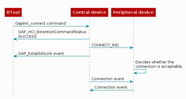
Establish connection flow diagram#
Task 2 - Set up a connection with basic_ble on both central and peripheral device#
The purpose of this section is to know a bit more about basic_ble with central role.
Thus, flash one of your SimpleLink™ CC2340R5 Modular LaunchPad™ with basic_ble in a Central role (follow the Role on Sysconfig picture to know how to change the configuration).
Once your device is flashed, open a serial terminal on the dedicated PORT COM of your device (XDS110 Class Application/User UART (COMXX)).
You should have a similar display than below, note that your BLE ID Address and your BLE RP Address should be different.
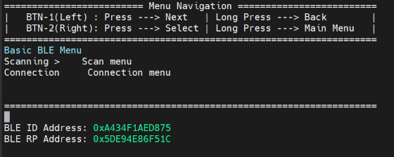
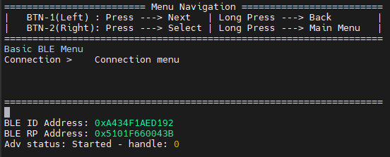
Central role serial terminal display on UART port#
Now the central device is ready to use, you’ll be able to scan, connect and change basic stuff through the menu. Use the buttons of your device to navigate in the menu.
To scan for potential devices advertising, press the right button to select Scan menu then Scan for devices.
After the scanning, the display shows a scan status:
Scan status: Scan disabled - Reason: X Num results: X
The reason parameters represents if the scanning was interrupt by user request (0) or by duration expiration (1).
The Num results parameters represents the number of recorded advertising reports.
To connect to a specific device, go back to the main menu, select Connection menu then Connect to a device and search the address
of your peripheral device.
With your second device flash the basic_ble in a peripheral role and open a serial terminal on the dedicated PORT COM (XDS110 Class Application/User UART (COMXX)).
You should have a similar display than below for your peripheral device, note that your BLE ID Address and your BLE RP Address should be different.
Peripheral role serial terminal display on UART port#
Here you can check the RP Address of your peripheral device, start the connection from the central side on this address.
After the connection, the display shows a Conn status on both side (central and peripheral):
Conn status: Established - Connected to 0xAAAAAAAAAAAAA connectionHandle = X
Hint
Now we have a peripheral connected to a central. Feel free to navigate in the Connection menu and the Work with a peer device one.
Task 3 - Create a oneshot or periodic clock using clockP module#
Let’s set up a timer on the basic_ble example. This code will be usefull to call specific functions, later in this lab. It exist three different ways to implement a Timer, the first one shows how to add a new event in the stack but need a deeper change in the embedded code and modify the SDK files. The second one and the third one use only an argument calling a callback function, the difference between both methods are the clock type.
This method is the easiest way to implement a clock with ClockP module. First include the rights librairies and all instances needed for the clock usecase.
Click to expand the code
app_peripheral.c file# #include <ti/drivers/dpl/ClockP.h>
#include <ti/bleapp/ble_app_util/inc/bleapputil_internal.h>
static ClockP_Struct clkPeriodic;
ClockP_Params clockpParams;
ClockP_Handle clockHandle;
#define SP_PERIODIC_EVT_PERIOD 5000
#define CLOCK_MS 1000
//*****************************************************************************
//! Prototypes
//*****************************************************************************
void Peripheral_AppEventHandler();
The Peripheral_AppEventHandler() is the function passed in argument at the clock construction. The BLEAppUtil framework manage the stack to run the function at the proper time. Thus, the stack is not disturbed by the new code.
Here you can find the code to initialize the clock.
Peripheral_start() function just before the BLEAppUtil_advStart() function.# // Setup parameters.
ClockP_Params_init(&clockpParams);
// Convert clockDuration in milliseconds to ticks.
uint32_t clockTicks = SP_PERIODIC_EVT_PERIOD * (CLOCK_MS/ 1);
// If period is 0, this is a one-shot timer. If not 0, the it’s a periodic clock.
clockpParams.period = 0; //clockTicks;
// Starts immediately after construction if true, otherwise wait for a call
// to start.
clockpParams.startFlag = false;
clockpParams.arg = (uintptr_t)Peripheral_AppEventHandler;
// Initialize clock instance.
clockHandle = ClockP_construct(&clkPeriodic, (void *)BLEAppUtil_invokeFunctionNoData, clockTicks, &clockpParams);
The Clock module is feature developped from FreeRTOS, then we don’t have any testing coverage for that module, so we recommend to use ClockP module.
app_peripheral.c file# #include "util.h"
#include <ti/bleapp/ble_app_util/inc/bleapputil_internal.h>
static Clock_Struct clkPeriodic;
#define CLOCK_DURATION 5000
//*****************************************************************************
//! Prototypes
//*****************************************************************************
void Peripheral_AppEventHandler();
The Peripheral_AppEventHandler() is the function passed in argument at the clock construction. The BLEAppUtil framework manage the stack to run the function at the proper time. Thus, the stack is not disturbed by the new code.
Here you can find the code to initialize the clock.
Peripheral_start() function just before the BLEAppUtil_advStart() function.# // Initialize clock instance.
Util_constructClock(&clkPeriodic, (void *)BLEAppUtil_invokeFunctionNoData, CLOCK_DURATION,0,0, (uint32_t) Peripheral_AppEventHandler);
Here the Util_constructClock() builds the clock with its structure (clkPeriodic), its duration (CLOCK_DURATION), its period (here 0), the start flag (here 0 → FALSE) and the callback function (Peripheral_AppEventHandler).
This method allows you to create a new event in the BLEstack in order to call a specific function.
First include the rights librairies and all instances needed for the Timer.
app_peripheral.c file# #include <ti/drivers/dpl/ClockP.h>
#include <ti/bleapp/ble_app_util/inc/bleapputil_internal.h>
static ClockP_Struct clkPeriodic;
ClockP_Params clockpParams;
ClockP_Handle clockHandle;
#define SP_PERIODIC_EVT_PERIOD 5000
#define CLOCK_MS 1000
//*****************************************************************************
//! Prototypes
//*****************************************************************************
void Peripheral_ClockCb();
void Peripheral_AppEventHandler();
Peripheral_ClockCb() function is the callback function called when the clock has end# void Peripheral_ClockCb(){
BLEAppUtil_enqueueMsg(BLEAPPUTIL_EVT_APP_EVENT, 0);
}
The BLEAppUtil_enqueueMsg() function create an event and put it in the queue, once the event is on the top of the queue the Peripheral_AppEventHandler() function is called to run your code. Thus, the stack is not disturbed by the new code. The code below is now necessary to add the new event to the stack.
Here is the code
First, make sure to create a local copy of the
bleapputil_task.cfile to not change the SDK files.Open the file and add the BLEAPPUTIL_EVT_APP_EVENT which call the
Peripheral_AppEventHandler()function.
BLEAppUtil_Task() function# case BLEAPPUTIL_EVT_CALL_IN_BLEAPPUTIL_CONTEXT:
{
((BLEAppUtil_CallbackToInvoke_t *)pMsgData)->callback(((BLEAppUtil_CallbackToInvoke_t *)pMsgData)->data);
// Verify that the data is not NULL before freeing it
if(((BLEAppUtil_CallbackToInvoke_t *)pMsgData)->data != NULL)
{
BLEAppUtil_free(((BLEAppUtil_CallbackToInvoke_t *)pMsgData)->data);
}
break;
}
/*** Add the line below ***/
case BLEAPPUTIL_EVT_APP_EVENT:
Peripheral_AppEventHandler();
break;
/*** end ***///
default:
break;
Then add this event to the BLEAppUtil events list. Open the
bleapputil_internal.cfile located in your SDK →source→ti→bleapp→ble_app_util→inc.
BLEAppBLEAppUtil_Evt_e strucutre.# typedef enum BLEAppBLEAppUtil_Evt_e
{
BLEAPPUTIL_EVT_STACK_CALLBACK, // BLE stack events
BLEAPPUTIL_EVT_ADV_CB_EVENT, // Advertisement Callback events
BLEAPPUTIL_EVT_SCAN_CB_EVENT, // Scan Callback events
BLEAPPUTIL_EVT_PAIRING_STATE_CB, // Pairing states event from GapBond manager callback
BLEAPPUTIL_EVT_PASSCODE_NEEDED_CB, // Passcode confirm from GapBond manager callback
BLEAPPUTIL_EVT_CONN_EVENT_CB, // connection event callback
BLEAPPUTIL_EVT_CALL_IN_BLEAPPUTIL_CONTEXT, // switch context and call callback
BLEAPPUTIL_EVT_APP_EVENT // add this line
} BLEAppBLEAppUtil_Evt_e;
Here you can find the code to initialize the clock and to start it.
Peripheral_start() function just before the BLEAppUtil_advStart() function.# // Setup parameters.
ClockP_Params_init(&clockpParams);
// Convert clockDuration in milliseconds to ticks.
uint32_t clockTicks = SP_PERIODIC_EVT_PERIOD * (CLOCK_MS/ 1);
// If period is 0, this is a one-shot timer. If not 0, the it’s a periodic clock.
clockpParams.period = 0; //clockTicks;
// Starts immediately after construction if true, otherwise wait for a call
// to start.
clockpParams.startFlag = false;
// Initialize clock instance.
clockHandle = ClockP_construct(&clkPeriodic, Peripheral_ClockCb, clockTicks, &clockpParams);
app_peripheral.c file# void Peripheral_AppEventHandler()
{
//add your code here
}
Find below a converter tool to know exactly the duration of the timer depending on the define CLOCK_MS.
| CLOCK_MS : |
| Timer is ms long |
To start the timer, you need to call the function below wherever you seem it’s better for your implementation.
ClockP_start(clockHandle);
Util_startClock(&clkPeriodic);
Hint
Let’s try to implement a specific function and see if your code works, by building and flashing it.
What is connection parameters#
When forming a connection, four parameters must be determined. They all have to do with the connection timing:
Connection Parameter |
Description |
Range |
Increment |
|---|---|---|---|
Min Connection Interval |
Minimum connection interval |
7.5 ms to 4 s |
1.25 ms |
Max Connection Interval |
Maximum connection interval |
7.5 ms to 4 s |
1.25 ms |
Peripheral Latency |
Number of skipped connection events |
0 - 499 |
x |
Supervision Timeout |
Connection supervision timeout |
100 ms to 32 s |
10 ms |
The connection parameters are set in the Central before initiating the
connection. GAP handles these parameters. In BTool, you can find the connection
settings just below the Discovery section. Please note that in BTool, these
connection settings cannot be used to update the connection parameters during
an active connection.
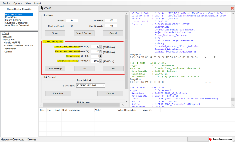
Connection Settings tab on BTool#
Note
Note that in BTool Min Connection Interval and Max Connection Interval are writting from 6 to 3200, these are increments units.
Connection Interval#
What’s Connection Interval#
The connection interval is the time between each connection event. The connection interval must be agreed upon by the two devices in the connection in order for them to be transmitting and receiving at the same time. The connection interval has to be between 7.5 ms and 4 s to comply with the [Bluetooth Core Specification Version 5.2]. Each connection event consumes power, therefore we generally want a large connection interval. On the other hand, the connection interval represents latency. This means that in a connection with 1 s connection interval, a button press on the Peripheral device might not be registered on the Central device before 1 s has passed.
The connection interval is defined in terms of a minimum and a maximum value. If you want your application to have a fixed connection interval, you can give both variables the same value. Sometimes we want to give the Central device the freedom to change the connection interval without any further input from the user. In that case, give the minimum and maximum variables different values. The Central device will then be free to change its connection interval, as long as it stays within the defined limits. Per default, the device will start with as large connection interval as possible (i.e. the max value will be chosen by the BLE stack as the connection interval) in order to minimize power consumption. Your peer device may have specific connection interval requirements so make sure the connection interval you choose is supported by the peer you wish to connect to.
Task 4 - How to modify the connection interval in my project#
For this section, the clock implemented in the create a oneshot or periodic clock using clockp module section is needed.
The function BLEAppUtil_paramUpdateReq() will be used to change the connection interval and the parameters of the following sections as well.
First we need to create a new request for the new connection parameters:
  gapUpdateLinkParamReq_t newReq =
  {
    .connectionHandle = 0,
    .intervalMin = DEFAULT_DESIRED_MIN_CONN_INTERVAL,
    .intervalMax = DEFAULT_DESIRED_MAX_CONN_INTERVAL,
    .connLatency = DEFAULT_DESIRED_PERIPHERAL_LATENCY,
    .connTimeout = DEFAULT_DESIRED_CONN_TIMEOUT,
    .signalIdentifier = 0,
  };
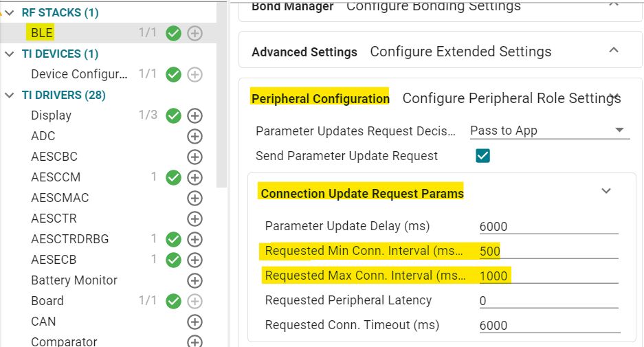
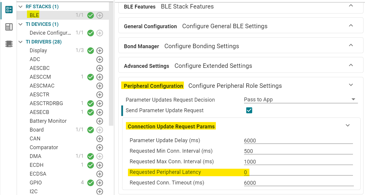
Connection Interval on Sysconfig#
This request reuse the parameters provide in sysconfig in the Peripheral Configuration → Connection Update Request Params section.
The define are not implemented in the embedded code yet so you can create your own request as shown above.
Then in the callback function Peripheral_AppEventHandler() you need to specify the connection handle and
call the BLEAppUtil_paramUpdateReq() function.
  void Peripheral_AppEventHandler()
  {
    newReq.connectionHandle = peripheralAdvHandle_1;
    state = BLEAppUtil_paramUpdateReq(&newReq);
  }
Peripheral Latency#
What’s Peripheral Latency#
The peripheral latency parameter allows the peripheral device to skip a number of consecutive connection events. During this time, the peripheral is not listening at the central connection events. The parameter corresponds to the number of connection events skipped. If the peripheral does not have any data to send, it can skip connection events, stay asleep, and save power. The peripheral can skip connection events but must not skip more than allowed by the Peripheral latency parameter or the connection fails. See picture below for more details.
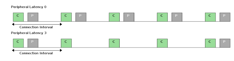
Diagram representing peripheral latency#
How to modify Peripheral Latency in my project#
To modify this connection parameter, you have to open your basic_ble.syscfg file. Open the BLE → Peripheral Configuration → Connection Update Request Params
section. Then, modify the value of Requested Slave Latency with the number of hop increment you want.
Peripheral Latency on Sysconfig#
Supervision time-out#
What’s Supervision time-out#
The Supervision time-out parameter is the maximum time between two received packets before the peripheral and the central connection is considered lost. If this time passes without a successful connection event, the device terminates the connection and returns to an unconnected state. This value is fixed at the beginning of the connection and could be between 100ms to 32s in increments of 10ms.
How to modify Supervision time-out in my project#
To modify this connection parameter, you have to open your basic_ble.syscfg file. Open the BLE → Peripheral Configuration → Connection Update Request Params
section. Then, modify the value of Requested Conn Timeout (ms) with the value you want.
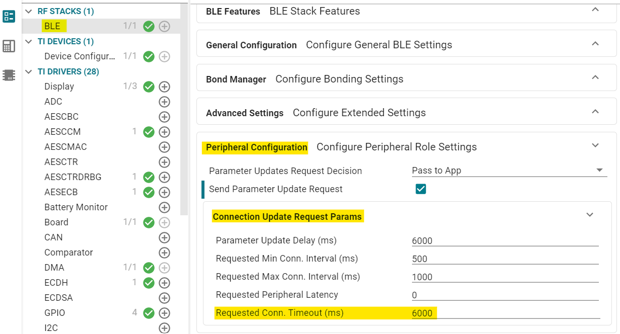
Supervision Time-out on Sysconfig#
Task 5 - End a connection with code execution#
Either the Central or the Peripheral can terminate a connection for any reason. One side initiates termination and the other side must respond before both devices exit the connected state. Use the GAP_TerminateLinkReq() command to terminate an existing connection.
Let’s program the Peripheral to disconnect at the end of the clock implemented in the clockp module section. The function, defined in GAP, tells GAP to terminate the connection. This gets broadcasted to the Central, along with a reason why the connection was terminated. Simultaneously, a GAP_LINK_TERMINATED_EVENT gets posted in the GAP message event queue. (This event gets posted whether the termination was intentional or not.) Let’s try to implement this, knowing that the function to terminate the connection should be like below:
GAP_TerminateLinkReq(<STORED_HANDLE_ADVERTISE_SET>,0x13);
Warning
Make sure your clock is already implemented as the
clockp module section
did, before trying to achieve this section.
Here is a solution how to use GAP_TerminateLinkReq()
First let’s start the clock just after the connection is established. To do so call the
ClockP_start()function as below:ThePeripheral_GAPConnEventHandler()function is located in theapp_peripheral.cfile#void Peripheral_GAPConnEventHandler(uint32 event, BLEAppUtil_msgHdr_t *pMsgData) { switch(event) { case BLEAPPUTIL_LINK_ESTABLISHED_EVENT: { /* Check if we reach the maximum allowed number of connections */ if(linkDB_NumActive() < linkDB_NumConns()) { /* Start advertising since there is room for more connections */ BLEAppUtil_advStart(peripheralAdvHandle_1, &advSetStartParamsSet_1); } else { ClockP_start(clockHandle);//Call the start here!
Call the function to end the connection and restart the advertisement for a later use, in the
Peripheral_AppEventHandler()function.
  void Peripheral_AppEventHandler()
  {
    GAP_TerminateLinkReq(peripheralAdvHandle_1,0x13);
    BLEAppUtil_advStart(peripheralAdvHandle_1, &advSetStartParamsSet_1);
  }
Hint
Flash your code on your SimpleLink™ CC2340R5 LaunchPad™. You should be disconnected 5s after you established the connection!
Task 6 - Customize your Project#
How to blink a LED for each specific event#
This section will describe more in details how to blink a led each time a connection event is caught. To do so, we will implement a new handler to catch a special event.
Create a new handler#
We need to create a new handler which has the BLEAPPUTIL__CONN_NOTI_TYPE type and where the BLEAPPUTIL_CONN_NOTI_CONN_EVENT_ALL event is registered.
Here is the code you should get to create the handler in app_peripheral.c
Open the app_peripheral.c file located in the app folder of your project. Create a handler
containing the wanting events. Thus, add the code below after other handlers.
Peripheral_GAPConnNotifyEventHandler()# BLEAppUtil_EventHandler_t peripheralConnNotifyHandler =
{
.handlerType = BLEAPPUTIL_CONN_NOTI_TYPE,
.pEventHandler = Peripheral_GAPConnNotifyEventHandler,
.eventMask = BLEAPPUTIL_CONN_NOTI_CONN_EVENT_ALL |
BLEAPPUTIL_CONN_NOTI_CONN_ESTABLISHED | BLEAPPUTIL_CONN_NOTI_EVENT_INVALID
};
Note
Don’t forget to add the prototype at the begining of the file
Register the handler#
Now we need to register the new handle created for Bluetooth LE stack events. In order to allocate it and to add it to your project handler list.
Here is the code to register the new handler
Then register the handler in the Peripheral_start() function located at the end of the app_peripheral.c file.
  bStatus_t Peripheral_start()
  {
    bStatus_t status = SUCCESS;

    status = BLEAppUtil_registerEventHandler(&peripheralConnHandler);
    if(status != SUCCESS)
    {
        // Return status value
        return(status);
    }

    status = BLEAppUtil_registerEventHandler(&peripheralAdvHandler);
    if(status != SUCCESS)
    {
        return(status);
    }
    //add the section below
    status = BLEAppUtil_registerEventHandler(&peripheralConnNotifyHandler);
    if(status != SUCCESS)
    {
        return(status);
    }
  //.....//
Enable connection event notifications#
In this section we call the handler for a specific connection handle once a connection between two devices is established.
Implement this code to enable the handler
Add also the BLEAppUtil_registerConnNotifHandler() function once the BLEAPPUTIL_LINK_ESTABLISHED_EVENT
appears in the Peripheral_GAPConnEventHandler() function.
  void Peripheral_GAPConnEventHandler(uint32 event, BLEAppUtil_msgHdr_t *pMsgData)
  {
    switch(event)
    {
      case BLEAPPUTIL_LINK_ESTABLISHED_EVENT:
      {
        BLEAppUtil_registerConnNotifHandler(peripheralAdvHandle_1); //add this line
        /* Check if we reach the maximum allowed number of connections */
        if(linkDB_NumActive() < linkDB_NumConns())
        {
            /* Start advertising since there is room for more connections */
            BLEAppUtil_advStart(peripheralAdvHandle_1, &advSetStartParamsSet_1);
        }
        else
        {
            /* Stop advertising since there is no room for more connections */
            BLEAppUtil_advStop(peripheralAdvHandle_1);
        }
        break;
      }
  //...//
Catch the event#
Here we use the handler to catch the right event and execute our specific code to blink the LED.
This is the code to blink the led after each connection event
Finally you can implement your code in the function Peripheral_GAPConnNotifyEventHandler() function.
If you don’t how to set up a LED in your syscfg file, have a look at the image below :
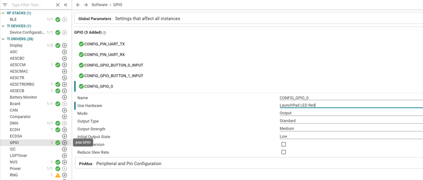
How to set up a LED in Sysconfig#
app_peripheral.c file# void Peripheral_GAPConnNotifyEventHandler(uint32 event, BLEAppUtil_msgHdr_t *pMsgData)
{
switch(event)
{
case BLEAPPUTIL_CONN_NOTI_CONN_EVENT_ALL:
{
GPIO_toggle(CONFIG_GPIO_LED_0);//Your LED implementation define in syscfg
break;
}
default:
{
break;
}
}
}
Hint
Build and flash your project, you should see on your launchpad the red LED blinks quite fast.
Further Reading#
In this SimpleLink Academy lab, we have talked a lot about what a Bluetooth LE connection is, but very little about its purpose. Usually, we want to exchange specific information between the two devices. This can be accomplished with Bluetooth Services and Characteristics. If you want to learn about this, you should move on to the SimpleLink Academy module.
References#
Code Composer Studio
Bluetooth Core Specification Version 5.3
BLE Scanning and Advertising
TI SimpleLink Connect App
SimpleLink CC2340R5 LaunchPad
SIMPLELINK-LOWPOWER-F3-SDK
SDK User’s Guide