Bluetooth Low Energy 5 PHY - 1M, 2M and Coded#
Texas Instruments
2 - 3 hours read
Introduction#
The 2Mbps and Coded Radio Physical Layer was added to the Bluetooth Core Spec in version 5. You can increase throughput by increasing data rate from legacy 1 Mbps to 2 Mbps or you can increase range by using coded PHY.
In this module we will learn about the Bluetooth® low energy (BLE) 5 physical layers (PHY), how to configure and switch PHY. The different benefits are listed in the table below. Note that by reducing the data rate, the average power consumption might increase because it takes more time to transmit and receive data causing longer intervals in active TX and RX states.
PHY |
Data Rate |
Theoretical Relative Range |
Advantage |
|---|---|---|---|
2 Mbps |
2 Mb/s |
~0.8x |
Speed (Throughput) |
1 Mbps |
1 Mb/s |
1x |
Compatilbility (balanced) |
Coded S2 |
500 kbps |
2x |
Range |
Coded S8 |
125 kbps |
4x |
Range x2 |
Note
Please consider the presentation What is Bluetooth 5 and When do I Use it? to quickly learn about the BLE 5 PHYs and features.
In this lab we will be working with the example project Basic BLE and BTool in order to form a BLE connection and issue a PHY change request. This SimpleLink Academy lab uses projects from the BLE5-Stack, which can be found in the SimpleLink Low Power F3 software development kit that was downloaded in Environment Setup.
If you are using the SDK from the Environment Setup lab the download location should be:
C:\ti\{SDK_INSTALL_DIR}\examples\rtos\LP_EM_CC2340R5\ble5stack
This tutorial will take about two hours to complete and requires basic embedded programming skills (see the Prerequisites section for details).
In the first task, BTool will be used to initiate a connection and send a Read Current PHY command (
HCI_LE_ReadPhy) from the central device using BTool.In the second task, we will try to send a change PHY request from the central device using BTool.
In the third task, we will try to send a change PHY request from the peripheral device instead.
In the fourth task, we are going to show what happens when a change PHY request is sent to a device that does not support LE 2M PHY.
In the first bonus task, we will change the connection’s PHY to an LE Coded PHY.
Error
This lab cannot be run from CCS Cloud. In order to do this lab, you need to install the relevant SimpleLink™ software development kit locally.
Prerequisites#
Hardware#
For this lab, you need two Bluetooth-enabled development boards. Supported devices are:
You will also need two XDS110ET boards for connecting to a computer:
Other SimpleLink Academy Labs#
Completion of SimpleLink™ Low Power F3 and CC2340Rx Environment Setup Guide
Completion of BLE Scanning and Advertising
Completion of BLE Connections
Software#
The following software will be used in this lab, which should already be setup from the environment setup guide’s Download and Install required software
CCS or IAR 8.50.9 installed with support for CC23xx devices
SimpleLink™ CC23xx Low Power F3 SDK
BTool (located in the
tools\ble5stackdirectory of the SimpleLink™ SDK installation) Setup Guide here
Setup#
To start with this training module, two LaunchPads will be programmed with
Basic BLE to act as a peripheral device.
Host Test to act as a central device.
If not already done, import Basic BLE and Host Test from the SDK as done in the environment setup guide’s Download and Install required software.
Both example projects can be found in the examples folder in the SDK.
About the LE PHYs#
The physical layer (PHY) is the lowest layer of the Bluetooth® low energy protocol stack. It configures the physical parameters of the radio transmission and reception. It determines how a bit (and its value) are represented over the air.
A full guide of the physical layer is given in the TI BLE5-Stack User’s Guide, see the PHY section located in BLE5-Stack → Physical Layer (PHY).
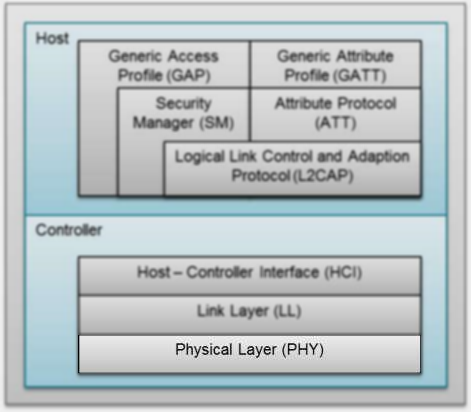
BLE stack overview#
One of the key parameters of a physical layer is the symbol rate. The symbol rate represents how many symbols are sent/received per second. For 1M PHY one symbol represents one bit (In other cases one symbol can represent more or less than one bit. E.g. in the LE Coded PHY, one bit can be represented by two or eight symbols.). When we switch from the 1 Mbps physical layer to the 2 Mbps physical layer, the symbol rate is doubled. This means that data is transmitted at twice the speed. The LE Coded PHY feature uses the same transmit power as the LE 1M PHY and the same symbol rate (1Mbps), the only change is in the modulation of data in the PHY where the bits are coded and is represented by either two symbols (LE Coded S=2, data rate 500kbps) or eight symbols (LE Coded S=8, data rate 125kbps). Using the LE Coded PHY, the energy consumption increases because the radio is in Tx longer.
The channel width is the same for all LE PHYs in order for them to coexist. When changing from LE 1M PHY to LE 2M PHY, the bandwidth goes up. However, the channel spacing in BLE is high enough (2 MHz) that this does not cause a problem.
The main advantage of the 2 Mbps physical layer over the 1 Mbps physical layer is that the transmission speed is increased. This means that the radio spends less time transmitting/receiving data. This will reduce the device energy consumption for sending the same amount of data. The main application for LE Coded PHY should be applications that need longer range (with the penalty of lower data rate).
A comparison of the physical layers is given in the following table.
Parameter |
Comparison |
|---|---|
Power consumption |
For the same transmit power, the energy consumption is reduced when using LE 2M PHY and increased when using CODED PHY. |
Data rate |
The LE 2M PHY is two times faster to transmit data than the LE 1M PHY, but actual application data throughput is lower due to overhead and protocol timing requirements. CODED PHY has lower data rate. |
Receive sensitivity |
The link budget will be lower in the LE 2M PHY relative to the LE 1M PHY, due to the increased symbol rate and the link budget will be higher for CODED PHY which can provide longer range. |
Transmit power |
The output power is same for all PHYs. |
Bluetooth 5 PHY Possibilities and Restrictions#
Although at the moment this section on theory remains, we are currently working to enable Advertising Extensions support in a future SDK.
In the SLA module BLE Scanning and Advertising, we learned that it is possible to advertise on all the Bluetooth low energy PHYs:
LE 1M PHY
LE 2M PHY
LE Coded PHY
According to the Bluetooth Core Spec v5.0, only AUX_ADV_IND, AUX_SYNC_IND and
AUX_CHAIN_IND can be sent on the LE 2M PHY. All these packets have to be
preceded by an ADV_EXT_IND packet sent on the LE 1M PHY. The ADV_EXT_IND
packets contain pointers to the extended advertising packet sent on the
secondary PHY.
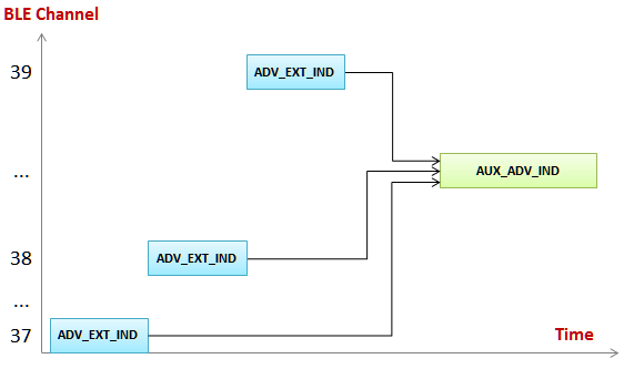
By using this method, a lot more advertising data can be sent when compared to Bluetooth 4.2 advertising (legacy advertising). (254 bytes per packets vs. 31 bytes per packet.) The drawback is that the overhead is increased; you have to transmit multiple packets, and the auxiliary advertisement packets contain the extended advertising header in addition to the advertisement data.
Note that there is no way of transmitting an advertisement packet on the LE 2M
PHY without first transmitting an ADV_EXT_IND packet on the LE 1M PHY.
In this SimpleLink Academy module we will change the PHY inside a connection.
PHY Change in a Bluetooth Connection#
Since the key parameters of the radio changes when we change the PHY of a connection, it is crucial that both devices in the connection agree on the PHY change. This is handled in the BLE5-Stack with a PHY change request.
The set PHY command is defined in the Bluetooth Core Spec as HCI_LE_Set_PHY.
You can read about the
HCI_LE_Set_PHYcommand in the Bluetooth 5 Core Spec, Vol 4, Part E, section 7.8.49 LE Set PHY Command for Core v5.4+.
In the Bluetooth Core Spec, all the HCI_LE_Set_PHY command parameters are
described. You can also see what events are generated by this command.
An HCI command is a command sent from the Host to the Controller (A
HCI LE command is a Bluetooth low energy specific HCI command.). In this case,
the application sends the command to the Link Layer (The Host, Controller,
HCI and Link Layer are shown in the figure in the About the LE 2M PHY
section.). In the following figure, you can see the HCI_LE_SetPhyCmd, and the
following LL_PHY_REQ and LL_PHY_RSP exchange over the air.
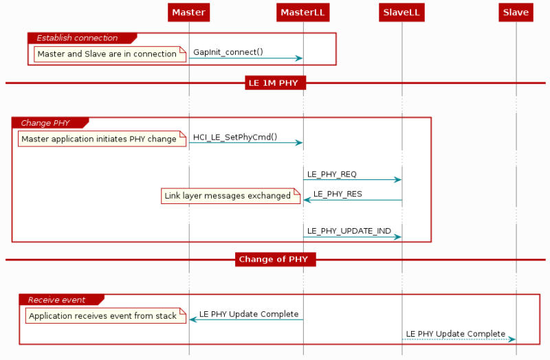
Both the central and the peripheral device are given the chance to refuse the PHY
change. In the LL_PHY_REQ and LL_PHY_RSP, each device indicates which PHYs
they prefer to use. The PHY will not be updated unless both devices have named
the PHY as a preferred PHY.
Task 1 – Initiate a Connection and Read the Current PHY#
Program one LaunchPad with Basic BLE, and one with Host Test from BLE5-Stack. (If you don’t remember how to do this, a description is given in BLE Connections.) Open a UART logging window for Basic BLE.
Open BTool by using the shortcut created in the Setup Guide. BTool file location:
C:\ti\{SDK_INSTALL_DIR}\tools\ble5stack\btool
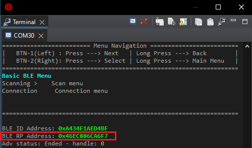
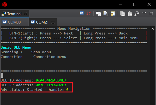
In order to connect with Basic BLE from BTool, we need the peripheral’s device address BDA (Bluetooth Device Address). The peripheral’s device address can be found in the UART log as ‘BLE RP Address’ - shown below:
In BTool, press the Scan button. BTool will start printing out
GAP_AdvertiserScannerEvent logs. Connect to Basic BLE by using its BDA.
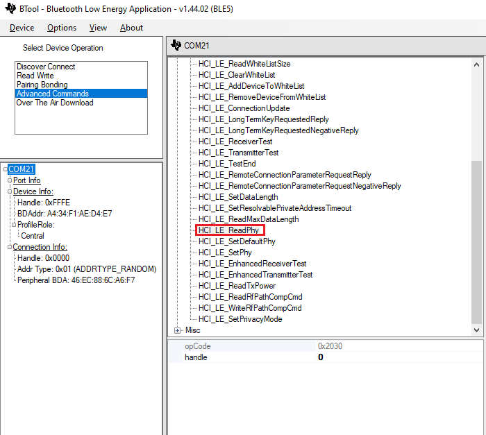
Now, that a link is established, we are going to try to figure out which PHY is
currently used in this connection. The command we will use is HCI_LE_ReadPhy,
which can be found under Advanced Commands in BTool.
You can read more about the
HCI_LE_ReadPhycommand in the Bluetooth Core Specification, Vol 2, Part E, 7.8.47 LE Read PHY Command.
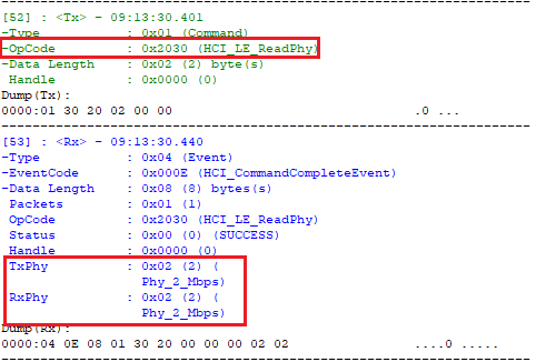
The HCI_LE_ReadPhy command is used to read the current transmitter PHY and
receiver PHY on the connection identified by the (connection) handle.
Once the HCI_LE_ReadPhy command is issued, the device which issued the command
will generate an HCI_CommandCompleteEvent(This is not surprising to anyone
who has read the return parameters for HCI_LE_ReadPhy in the Bluetooth Core
Spec.). The return event contains the following fields:
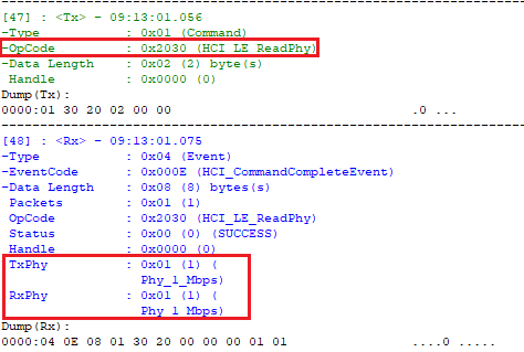
As you can see, the default PHY used to establish the connection is the LE 1M PHY. The table shows how to interpret different return values for the TxPhy and RxPhy fields.
Value |
Definition |
|---|---|
1 |
The transmitter/receiver PHY for the connection is LE 1M PHY. |
2 |
The transmitter/receiver PHY for the connection is LE 2M PHY. |
3 |
The transmitter/receiver PHY for the connection is LE Coded PHY. |
Task 2 – Send ‘Change PHY Request’ using BTool#
As described in the PHY section of the TI BLE5-Stack User’s Guide (located in BLE5-Stack → Physical Layer (PHY)), BLE5 projects in the SimpleLink SDK will by default support both the LE 1M PHY and the LE 2M PHY.
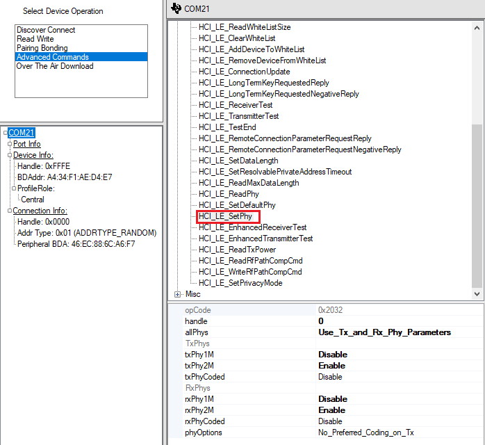
To change the PHY used in a connection, we can use the HCI_LE_SetPhy command,
which can be found under Adv. Commands in BTool.
In order to use this command, we need to understand all the parameter fields.
The parameters of
HCI_LE_SetPhyare listed in the Bluetooth Core Specification, Vol 2, Part E, section 7.8.49 LE Set PHY Command.
The following lists all the parameters for HCI_LE_SetPhy and explains the
parameters.
Parameters for HCI_LE_SetPhy#
Note
Handle
This is the connection handle. For more information regarding how to identify the current connection handle, please take a look at the SimpleLink Academy training module BLE Connections.
AllPhys
The host preference on how to handle txPhy and rxPhy. There are four options for the allPhys field:
Option |
Definition |
|---|---|
Use_Tx_and_Rx_Phy_Parameter |
The final preferred PHY setting will be taken from the txPhy and rxPhy fields |
Any_Tx_Phy_Use_Rx_Phy_Parameter |
The final preferred PHY setting will be taken from the rxPhy field |
Use_Tx_Phy_Parameter_Any_Rx_Phy |
The final preferred PHY setting will be taken from the txPhy field |
Any_Tx_or_Rx_Phy |
The sender does not have a preferred PHY. The txPhy/rxPhy fields will be ignored. The current PHY will be updated to the fastest PHY both devices support. |
TxPhy & RxPhy
Bit field of Host preferred Tx and Rx PHYs. The definition of the txPhy and rxPhy fields are shown below. In Btool, these bit fields can be toggled by selecting Enable or Disable for each txPhy and rxPhy option:
Bit Number |
Value |
Definition |
|---|---|---|
0 |
1 |
The host prefers to use LE 1M PHY as Tx/Rx PHY. |
1 |
2 |
The host prefers to use LE 2M PHY as Tx/Rx PHY. |
2 |
4 |
The host prefers to use LE Coded PHY as Tx/Rx PHY. |
The TI BLE5-Stack does not support asymmetric connections, i.e. connections where different PHYs are used for Rx and Tx.
PhyOptions
Bit field of the Host’s preferred Coded PHY options. We are not going to discuss
the LE Coded PHY in this training, we will just use No_Preferred_Coding_on_Tx
for this setting.
Changing PHY#
Choose parameters to change to LE 2M PHY. (If you’re unsure of what to choose, look at the printout from BTool below.) Send the command. When the command is sent, BTool will output the following:
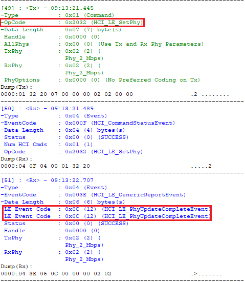
To verify that we actually changed the PHY, we can use HCI_LE_ReadPhy.
Warning
When changing the active PHY, the preferred PHY of the PHY change initiating device will also be changed automatically. This means that in some cases, only the device that first changed the active PHY to LE 2M PHY can change it back to LE 1M PHY. The device that initiated the PHY change to LE 2M will still be able to change the PHY back to LE 1M.
Because of this, it is a good idea to change the PHY to 0x03(LE 1M PHY | LE 2M
PHY) when the application has finished all LE 2M critical operations. This will
allow the peer device to change the PHY back to LE 1M.
Task 3 – Change PHY from Basic BLE#
So far we have learned how to change the PHY using BTool. Now we are moving on to
changing PHY from Basic BLE by a button press. We will use a button press
callback function where the HCI_LE_SetPhyCmd() is sent. This process is already
included in the SDK and this lab will show what changes are needed to implement
the process, what the process is doing behind the scenes, and include details on
how the HCI_LE_SetPhyCmd works.
We will be using HCI_LE_SetPhyCmd() in the Basic BLE code. The
parameters of this function are the same as when using the command in BTool,
however their values are slightly different.
Please see the manual here for the API description of
HCI_LE_SetPhyCmd(). The first code block immediately below shows the implementation forHCI_LE_SetPhyCmd().
hciStatus_t HCI_LE_SetPhyCmd( uint16  connHandle,
                              uint8   allPhys,
                              uint8   txPhy,
                              uint8   rxPhy,
                              uint16  phyOpts );
The code block directly below this statement -
Definiton of BLEAppUtil_setConnPhy() - shows the function that passes
through the input parameters to HCI_LE_SetPhyCmd(), which sends the commands
to change the PHY at the hardware level.
/**
 * @brief Phy Preference on the current connection.
 *        Should be created by the application and passed to @ref BLEAppUtil_setConnPhy
 */
bStatus_t BLEAppUtil_setConnPhy(BLEAppUtil_ConnPhyParams_t *phyParams)
{
    // Set Phy Preference on the current connection. Apply the same value
    // for RX and TX. For more information, see the LE 2M PHY section in the User's Guide:
    // http://software-dl.ti.com/lprf/ble5stack-latest/
    return HCI_LE_SetPhyCmd(phyParams->connHandle, phyParams->allPhys, phyParams->txPhy, phyParams->rxPhy, phyParams->phyOpts);
}
If you hold your mouse pointer over the function inputs/declarations
(BLEAppUtil_ConnPhyParams_t) you can see the details of what the required
inputs are, and this is shown in the code block immediately below
(”Definiton of BLEAppUtil_setConnPhy() inputs”). Notice that the
BLEAppUtil_setConnPhy() inputs are the same as the HCI_LE_SetPhyCmd() inputs.
/**
 * @brief Phy Preference on the current connection.
 *        Should be created by the application and passed to @ref BLEAppUtil_setConnPhy
 */
typedef struct
{
    uint16 connHandle;      //!< Connection handle
    uint8  allPhys;         //!< Host preference on how to handle txPhy and rxPhy
    uint8  txPhy;           //!< Bit field of Host preferred Tx PHY
    uint8  rxPhy;           //!< Bit field of Host preferred Rx PHY
    uint16 phyOpts;         //!< Bit field of Host preferred PHY options
}BLEAppUtil_ConnPhyParams_t;
The above code block is also the definition of the parameter phyParams.
Send HCI_LE_SetPhyCmd() Using the Menu#
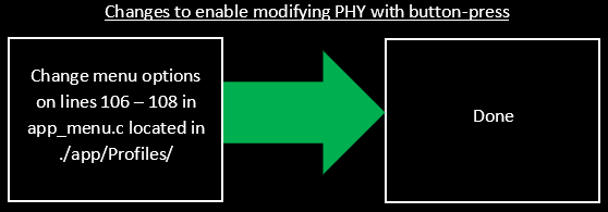
The basic_ble example comes with a built-in process for sending the HCI_LE_Set_PhyCmd() with buttons through the menu. We will be enabling this in the example and discuss a little bit about what the built-in process is doing. The changes needed to implement the process in the current code is shown in a dragram here:
To do this and enable changing the PHY with a button press, we need to find the
mainMenu[] function located in ./app/Profiles/app_menu.c. Lines 106 - 108
implement the menu functionality when you are in ‘Peripherial’ mode of the
example. This is where the callback functions are mapped to be selectable in the
menu through a button press.
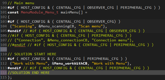
Copy and paste the following code over lines 99 - 109 in the app_menu.c file.
Line 99 should be “// Main menu” and line 109 should be “};”.
// Main menu
#if ( HOST_CONFIG & ( CENTRAL_CFG | OBSERVER_CFG | PERIPHERAL_CFG ) )
const MenuModule_Menu_t mainMenu[] =
{
#if ( HOST_CONFIG & ( CENTRAL_CFG | OBSERVER_CFG) )
 {"Scanning", &Menu_scanningCB, "Scan menu"},
#endif // #if ( HOST_CONFIG & ( CENTRAL_CFG | OBSERVER_CFG ) )
//#if ( HOST_CONFIG & ( CENTRAL_CFG | PERIPHERAL_CFG ) )
// {"Connection", &Menu_connectionCB, "Connection menu"},
//#endif // #if ( HOST_CONFIG & ( CENTRAL_CFG | PERIPHERAL_CFG ) )

// SOLUTION START HERE
#if ( HOST_CONFIG & ( CENTRAL_CFG | PERIPHERAL_CFG ) )
 {"Work with Menu", &Menu_workWithCB, "Work with Menu"},
#endif // #if ( HOST_CONFIG & ( CENTRAL_CFG | PERIPHERAL_CFG ) )
//SOLUTION END HERE
};
It should now look like this:
What’s going on behind the changes made:
If you would like to either implement this process yourself or understand how the code is operating, the figure below shows what the code is doing and the important objects that implement the process. The changes we made are including a new menu that allows the user to send a particular command in the menu with the buttons. In the below figure, the ‘phyParams’ object contains the selected settings and is passed through different functions to transmit these settings to the peripherial device and enable these settings in both devices.
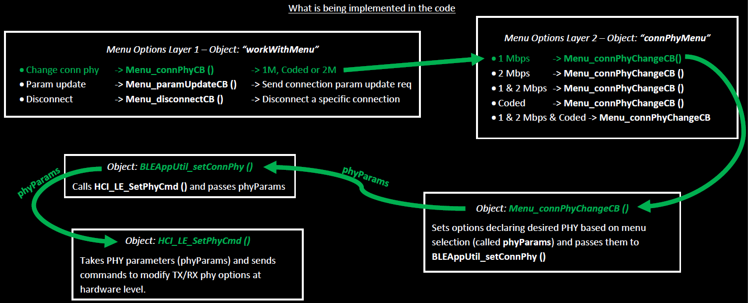
The top two blocks Menu Options Layer 1 - Object: “workWithMenu” and Menu Options Layer 2 - Object: “connPhyMenu” show the menu being implemented to change the PHY and the coded objects being called with each menu option.
The bottom three blocks show which objects are being used to implement the process in the code and what the objects are doing.
Note
The details on this flowchart’s components are covered at the start of Task 3.
Now that we have made the necessary changes and covered what is happening behind the scenes, we will continue with the exerciess.
Build, flash, and click ‘run’
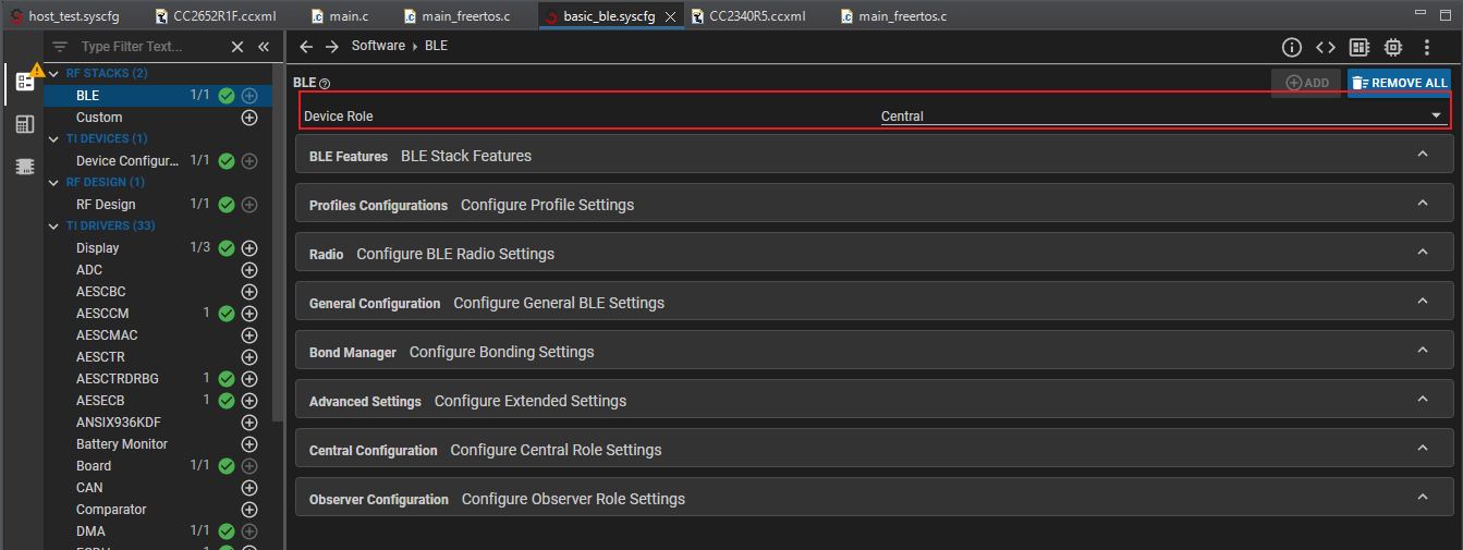
One device with basic_ble with ‘Device Role’ = ‘Central’
Another device with basic_ble with ‘Device Role’ = ‘Peripherial’.
This option is available in the basic_ble.sysconfig file and under ‘BLE’ in the submenu ‘RF STACKS (2)’. The option will be at the top of the menu shown here:
It is recommended to place the device antenna’s extremely close (ontop of eachother works) to reduce the liklihoood and impact of any interference. The Peripheral device should show a UART output log with ‘Adv status: Started - handle: 0’ below ‘BLE RP Address: …’.
With the Central device, go into the ‘Scanning > Scan menu’ option, then into ‘Scan > Scan for devices’ option, then go back to the main menu and into the ‘Connection Connection menu’, then go into ‘Connect > Connect to a device’, thenselect the BLE RP Address for your Peripherial device.
There should now be an updated UART log for both devices that shows a number for connections (likely 1) and a ‘Conn status: Established - Connected to … ‘ as shown in the figure directly below.
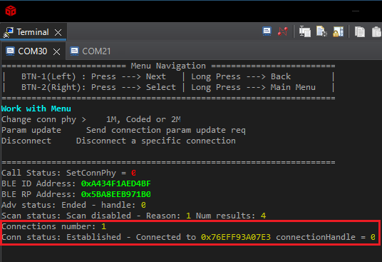
Note
If you are unable to find your device and connect, keep re-scanning until you see your device. You may need to reset your boards by pressing the XDS110 button and restart from number 2.
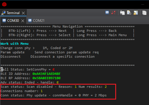
On the Central device, go to ‘Work with Work with a peer device’, select the Peripherial’s BLE RP Address, select ‘Change conn phy > 1M, Coded, or 2M’, then select ‘2 Mbps’.
Once the HCI_LE_SetPhyCmd() is sent, the Central’s controller will post a
hciEvt_BLEPhyUpdateComplete_t event.
If the HCI_LE_SetPhyCmd() is executed successfully, HCI_LE_SetPhyCmd() will
return status = SUCCESS. Then you will see the below image.
Task 4 – Send a PHY Change Request to a Device that Does Not Support BLE 5#
Connect Basic BLE to a phone/central device that does not support BLE 5. Older smart phones are the devices that may not support ble5. You have to terminate the connection with the Peripherial in order to do this. Navigate the menu and select 2 Mbps to update the connection to LE 2M PHY. Please note that recently released phones do have BLE 5 support. Do a quick internet search of your phone model’s BLE support to check if you can use your phone for this task.
You will see the ‘Conn status: Phy update - failure, peer does not support this’ in place of the ‘Conn status: Established…’ that is shown above.
As you can see from the Basic BLE log, the PHY update failed. When the phone
(the central in this connection) receives the phy request packet, it does not
recognize it since it does not support Bluetooth 5. The phone responds with a
HCI_ERROR_CODE_UNSUPPORTED_REMOTE_FEATURE packet. This is illustrated in the
following flow chart.
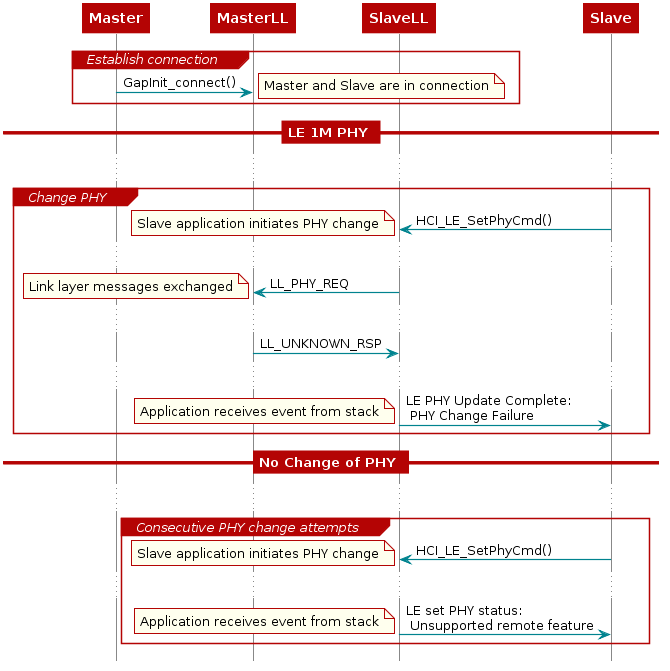
The first time Basic BLE attempts changing the PHY and the phone replies with
HCI_ERROR_CODE_UNSUPPORTED_REMOTE_FEATURE, the Link Layer notes that the phone
does not support PHY change. The next time you try to change to LE 2M PHY, HCI
will notify the Basic BLE application that this feature is not supported
directly. This time, no packets are sent over the air.
If you want to see how the PHY change failures are handled, check out
BLEAppUtil_processHCIGAPEvents() in bleapputil_process.c.
Bonus Task 1 – Change to Coded PHY#
We can use HCI_LE_SetPhyCmd() to change the connection PHY to a LE Coded PHY.
These PHYs increase the range of the BLE connection.
If you want to know more about the LE Coded PHYs and how to increase the range, please see How does Bluetooth® 5 increase the achievable range of a Bluetooth low energy connection?
You can also read more about LE Coded PHY in the TI BLE5-Stack User’s Guide, located in BLE5-Stack → Physical Layer (PHY) → LE Coded PHY.
You can use the HCI_LE_SetPhy command to change to the LE Coded PHY. The
bit-mask value for LE Coded PHY is 0x04. You can use either BTool or Project
Zero to change to LE Coded PHY.
Note
Supported PHYs As previously mentioned, if multiple PHYs are supported the PHY with the highest data throughput will be chosen by the controller. Thus, if there are multiple supported PHYs, the LE Coded PHY will not be chosen.
When changing to the LE Coded PHY, you can choose whether you prefer the S=2
coding or the S=8 coding in the phyOptions parameter. You can read about the
coding options in the TI BLE5-Stack User’s Guide located in BLE5-Stack →
Physical Layer (PHY) → LE Coded PHY.
References#
How does Bluetooth® 5 increase the achievable range of a Bluetooth low energy connection?