MAC and Frequency Hopping
The Wi-SUN FAN Specification implements a frequency-hopping configuration where the network devices hop on different frequencies. TI Wi-SUN FAN Stack supports an unslotted channel-hopping feature based on the directed frame exchange (DFE) mode of the Wi-SUN FAN specification v1.0. (For users familiar with TI 15.4-Stack, the same FH mode is implemented in this stack.)
Channel hopping is a feature by which a node shall hop or move to different channels (frequency bands). The channel hopping behavior has two advantages:
Increased network throughput by promoting simultaneous data transfer over multiple channels between different pair of nodes
Increased reliability in noisy channel conditions by exploiting the channel diversity.
According to Wi-SUN FAN Specification, only non sleepy nodes are allowed. Each node shall maintain its broadcast schedule as well as a unicast schedule.
The broadcast mechanism is used to send data to multiple recipients.
The unicast mechanism is used to send data to one unique recipient.
Broadcast Channel Hopping Schedule
The node will transmit its broadcast data during its broadcast schedule and its neighbors who are already tracking this node are expected to listing in its channel during the broadcast slot. The broadcast hopping pattern and some terms are shown below.
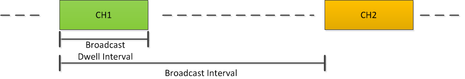
Figure 20. Broadcast Channel Hopping Sequence
Unicast Channel Hopping Schedule
During the broadcast interval, the nodes shall follow their own receiver-directed unicast channel hopping schedules. It’s not necessary for the unicast channel hop slots to be synchronized.
The unicast schedules are always receiver directed in the sense that a node shall transmit the frame in the receiver’s channel using CSMA/CA. This is illustrated in Figure 21.. As you can see, each node maintains its own hopping pattern.
The Wi-SUN FAN Specification describes the mechanisms for how a device can synchronize itself to the receiver node in order to successfully transmit a unicast packet to it. These mechanisms rely on exchange of appropriate information called Information elements (IEs). IEs can be exchanged either during the joining of the network or during the network operation time.
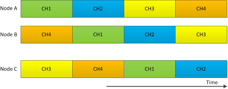
Figure 21. Unicast Hopping Sequence
Join Process
A brief walk-through of the joining process is given in fig-node-joining
More detail is given below.
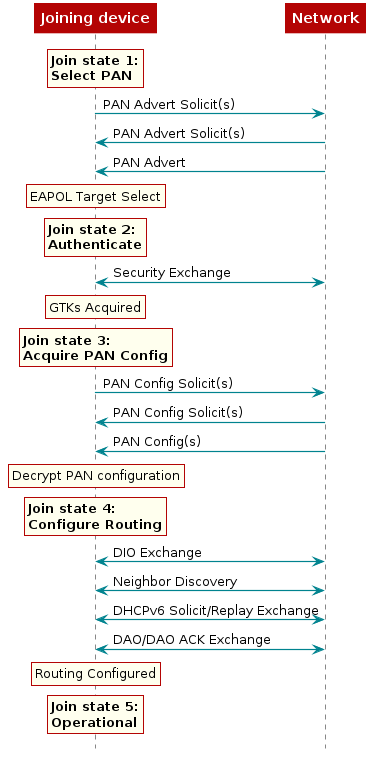
Joining State 1: Select PAN
The device sends PAN advertisements and receives PAN Advert Solicit packets. This will give an image of what network(s) are in operation in the area. The device then selects the PAN to join. PAN Advert and PAN Advert Solicit packets are sent asynchronously.
Joining State 2: Authenticate
EAPOL layer authenticates the PAN. In case of EAPOL fail, go back to joining
state 1. The joining device performs a security exchange with a neighbor router
node (or BR) over unicast. After the authenticate state, the node will acquire
GTKs.
Joining State 3: Acquire PAN Config
The joining device and network sends out PAN Config Solicit packets. In reply the joining device gets a PAN Config packet. PAN Config and PAN Config Solicit packets are sent asynchronously. In case of PCS_Max, the PAN configuration request will be unsuccessful and the joining device will start again from join state 1.
When the PAN Config is received, it will be decrypted using GTKs.
Joining State 4: Configure Routing
In this state, the joining device will do the following:
The joining device will form its link local IPv6 address.
The joining device will listen for RPL DIOs, and form its RPL candidate parent set by applying the RSL threshold to the set of neighbors from which it has received a RPL DIO.
The joining device will perform unicast Neighbor Discovery (Neighbor Solicit using its link local IPv6 address) with all neighbors from which it has received a RPL DIO (thereby collecting ETX and bi-directional RSL for the neighbor).
The joining device will determine its RPL parent/preferred upward route by submitting the candidate parent set to the MRHOF objective function.
The joining device will perform DHCPv6 to acquire GUAs and/or ULAs.
The joining device will unicast a RPL DAO to the Border Router.
Joining State 5: Operational
The joining device is now an operational router in the network. As such it can add new devices to the network.