EAPOL Layer
The Extensible Authentication Protocol over LAN (EAPOL) layer is responsible for authenticating devices in the Wi-SUN network.
Wi-SUN FAN networks mandate encryption of packets at the MAC level as well as allowing only authentic devices with right credentials to join the network. As per the Wi-SUN FAN Specification, EAPOL is used to exchange identities and to install the keys required to establish an encrypted connection.
Four types of keys are used for achieving security in the network:
Pairwise Master Key (PMK): Installed during authentication and used to derive PTK.
Pairwise Temporal Key (PTK): The packet containing the GTK is encrypted using a pair wise common key called PTK.
Group Transient Key (GTK): Installed on the node during the joining process.
Group AES Key (GAK): All devices within a Wi-SUN FAN and PAN network use a common key called GAK for encrypting packets at MAC layer. The GAK is derived from the GTK.
In TI Wi-SUN FAN examples, the EAPOL authenticator runs on the border router itself, and the nodes which have already joined the network provide EAPOL relay services to the joining node or the EAP supplicant.
Details of the process between the EAP supplicant, relay agents, authenticator and authentication server can be found in the Wi-SUN FAN Specification.
Usage of NV for Storing Keys
Keys and network information can be stored in flash by using the non volatile (NV) layer.
On-chip non volatile storage is used by both border router and router devices for storing different information related to network, keys, frame counter etc.
On both border router and router devices, 16 kB of flash is reserved for these needs. This can be increased through the SysConfig interface as needed.
On the router side, following information is stored in the NV:
Network & GTK related info: pan_id, network name, own-self EUI-64 and for each GTK: GTK expiry time stamp + install order + actual key value
PTK and PMK related info: PMK + PMK lifetime + PMK replay counter + PTK + PTK lifetime
Frame counter related info: restart counter + stored time + pan version + (GTK + frame counter) for every GTK key
On the border router side, apart from network & GTK related info, Frame counter related info and the pair wise key information is stored for every device in the network.
Enable NV to Store Keys
In order to enable NV to store keys and related network information, it is required to perform the following steps:
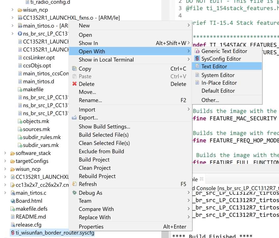
After importing your project, right click the SysConfig file associated with the project to open using the default CCS text editor:
On line 55 in the SysConfig file, paste in the following code to add the NVS Module in SysConfig. Please note that depending on role (Border Router vs Router Node), the
regionBaseis different.
/* ======== NVS ======== */
var NVS = scripting.addModule("/ti/drivers/NVS"); // Add a NVS module
var NVS_INT = NVS.addInstance(); // Add an internal NVS module instance

NVS_INT.$name = "CONFIG_NVSINTERNAL"; // Internal NVS
NVS_INT.internalFlash.regionBase = 0xAA000;
NVS_INT.internalFlash.regionSize = 0x4000;
/* ======== NVS ======== */
var NVS = scripting.addModule("/ti/drivers/NVS"); // Add a NVS module
var NVS_INT = NVS.addInstance(); // Add an internal NVS module instance

NVS_INT.$name = "CONFIG_NVSINTERNAL"; // Internal NVS
NVS_INT.internalFlash.regionBase = 0x52000;
NVS_INT.internalFlash.regionSize = 0x4000;
Save and close the SysConfig file.
Open Project -> Properties -> Build -> Arm Compiler -> Predefined Symbols -> Pre-define NAME and add a predefined symbol:
NV_RESTOREThe NV layer provides APIs for initializing the driver, storing, updating and clearing data from NV. The user application should however ensure the NV driver is initialized before any NV related APIs are called. In the TI Wi-SUN fan SDK examples, the code related to NV initialization can be found in
main_tirtos.cfile as below. Make sure to save the NV driver’s API function pointers in the pointerpNV, so that the TI Wi-SUN FAN stack can use them to store/retrieve data from NV.// Setup the NV driver NVOCMP_loadApiPtrs(&Main_user1Cfg.nvFps); // Do NV init if(Main_user1Cfg.nvFps.initNV) { Main_user1Cfg.nvFps.initiNV( NULL ); } // Save off the NV function pointers pNV = &Main_user1Cfg.nvFps;
The information stored in NV is updated when needed, based on a slow timer managed by the TI Wi-SUN FAN Stack or when there is an update in the keys used.
To clear NV content for a fresh start, see the section 2. Erasing the NV.
Certificates for Certification
Wi-SUN requires the use of x.509 (RFC 5280) based certificates. The device identifier should be based on IDevId as defined in IEEE 802.1AR.
There are two types of certificates that needs to be configured for a Wi-SUN device:
- Root Certificate(s):
This forms the trusted root certificate(s) to validate other devices
- Device Certificate and corresponding private key. Components are:
Device certificate to be sent to the other device for authentication
Private key corresponding to the device certificate to be used for key exchange. (Note: the private key will not be sent over the air and is used internally only)
In the SimpleLink CC13xx/CC26xx SDK examples, default certificates are enabled. A guide is provided to enable and change certificates.
Configure Certificates
Open
mbed_config_app.h. You can find this file in the example project in the following folder:mbed\nanostack\sal-stack-nanostack\source\configs.Configure the following defines:
#define MBED_CONF_MBED_MESH_APP_CERTIFICATE_HEADER                            "wisun_certificates.h"
#define MBED_CONF_MBED_MESH_APP_OWN_CERTIFICATE                               WISUN_CLIENT_CERTIFICATE
#define MBED_CONF_MBED_MESH_APP_OWN_CERTIFICATE_KEY                           WISUN_CLIENT_KEY
#define MBED_CONF_MBED_MESH_APP_ROOT_CERTIFICATE                              WISUN_ROOT_CERTIFICATE
An example implementation of the file
wisun_certificates.his given in the example project folderapplication. TO use your own certificates, modify or provide your own version of this file. Only PEM format is supported for certificates and key.Adding certificates are done with the
wisun_taskletAPIs, defined inwisun_tasklet.h.wisun_tasklet_set_trusted_certificatewisun_tasklet_remove_trusted_certificateswisun_tasklet_remove_own_certificateswisun_tasklet_set_own_certificate
6LoWPAN Layer
The goal of the 6LoWPAN protocol is to support the IPv6 Layer IP services by reducing the gap between IPv6 and lower stacks. This serves IPv6 applications on the low-end devices typically restricted in processing power, memory, and energy. The primary tasks of the 6LoWPAN are:
fragmentation and reassembly
IPv6 and UDP header compression
stateless IPv6 address auto-configuration
neighbor discovery optimization.
For details of the 6LoWPAN protocol, see the RFC standards RFC 4944 and RFC 6282 or the Wireless Network Challenges and Solutions for a Smarter Grid IoT TI Training video.
IPv6 Layer
In a Wi-SUN FAN network, all devices have an assigned Internet Protocol v6 (IPv6) address.
Routing Layer (RPL)
The Wi-SUN FAN Specification mandates usage of a routing protocol for low-power and lossy networks (RPL) algorithm in non-storing mode to achieve layer 3 routing. This protocol assigns the following roles in the network:
Root: First device in the mesh network, other devices join the root. For each device joining the network, a hierarchical connection is formed.
Parent: Device closer to the root. The parent can act as proxy for their child.
Child: Device farther from the root. Interacts with the root through the parent.
The network formation with RPL routing is initiated by broadcasting Destination Oriented Directed Acyclic Graph (DODAG) information object (DIO) by the Border router as well the nodes who can provide routing services to/from the border router.
During the process of joining the network, a new child node receives the DIOs, then selects the best possible parents (minimum 2 parents if possible) who can provide the best possible route to the border router i.e. root of the RPL tree. The preferred parent is chosen by a RPL metric. Per default, the RPL metric is the expected transmission count (ETX). Thus the preferred parent will be the one with the fewest expected transmissions to the border router.
The selected parent information is conveyed to the border router using DAO messages. After updating its routing tables, the border router acknowledges the receipt of DAO packet by sending DAO ACK back to the newly joined node. (The DIO and DAO transmission times are determined by the trickle algorithm (RFC 6206).)
You can see a figure of all the steps in the node joining process in the Join Process chapter.
For details on RPL routing, see the RFC standard RFC 6550 or the Wireless Network Challenges and Solutions for a Smarter Grid IoT TI Training video.