MT Interface
Introduction
Multiple end applications require communication between a host tester and Zigbee device. The Monitor and Test (MT) interface supports this functionality through a RS-232 serial port and UART protocol. As such the user can issue MT commands to the Zigbee target through a PC application or host MCU. MT commands are separated into several categories, the most important of which are highlighted below:
MT_AF&MT_ZDO: Allows the tester to interact with the target’s respective Z-Stack layer. The AF (Application Framework) interface allows the application process to register its application in order to send and receive data. The ZDO (Zigbee Device Object) interface provides varios Zigbee management functions like device and service discovery.MT_SYS: Provides the application processor with a low level interface to the ZNP hardware and software to perform resets, read/write memory or extended addresses, etc.MT_UTIL: Supports functionalities such as setting PAN-ID, getting device/NV info, subscribing callbacks, etc.MT_APP: Includes Base Device Behavior (BDB) functionality such as setting Install Codes or Primary/Secondary Channels, triggering different commissioning methods, and other Trust Center configurations. Also allows for custom tests or user-defined profiles.MT_GP: Enables interaction with Green Power (GP) stubs.
For further details on the MT interface, refer to the Z-Stack Monitor and Test API. You can also reference the Zigbee Network Processor (ZNP) Interface which already implements this communication layer in the provided SDK example.
Adding MT to a SimpleLink CC13xx/CC26xx SDK Zigbee 3.0 Project
The following steps provide instuctions necessary to support a MT interface inside a SimpleLink CC13xx/CC26xx SDK Zigbee 3.0 Project. The zc_genericapp CCS example will be used for reference, please refer to the Z-Stack Quick Start Guide to get started with importing a project into the IDE.
Note
Please refer to OTA Server Application for an example in which the MT interface has already been enabled.
1. Implement Changes to the Main Application and Task Files
Add the following header includes and global function to Application/zcl_genericapp.c
#include "npi_data.h"
#include "npi_task.h"

#include "mt.h"
#include "mt_af.h"
#include "mt_rpc.h"
#include "mt_sys.h"
#include "mt_util.h"
#include "mt_zdo.h"
#include "mt_nwk.h"
#include "mt_app.h"
#include "string.h"

/*********************************************************************
 * GLOBAL FUNCTIONS
 */

uint8_t appTask_getServiceTaskID(void);
Then define the appTask_getServiceTaskID at the end of the file
uint8_t appTask_getServiceTaskID(void)
{
    return appServiceTaskId;
}
2. Link to or Copy ZNP Application Files and Z-Stack Folders
In your file explorer, navigate to C:\ti\<SimpleLink SDK Path>\source\ti\zstack\
and copy the mt and npi folders into the Application folder of your project. The
mt\debug_trace and npi\npi_tl_spi files can be removed.
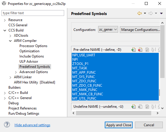
3. Include Predefined Symbols and Options
Open up the Project Properties and go to CCS Build → ARM Compiler → Predefined Symbols and add the following:
NPI_USE_UARTNPIMT_UTIL_FUNCMT_SYS_FUNCMT_AF_FUNCMT_ZDO_FUNCMT_ZDO_CB_FUNCMT_ZDO_MGMTMT_ZDO_EXTENSIONSMT_GP_CB_FUNCMT_APP_FUNCMT_APP_CNF_FUNC
Make sure that
BOARD_DISPLAY_USE_UART is defined whereas CUI_DISABLE is not. In the
Include Options tab, add ${PROJECT_ROOT}/Application/[npi/mt] to the
#include search paths.
4. Verify Operation
The serial configurations are set by NPITLUART_initializeTransport of npi_tl_uart.c
void NPITLUART_initializeTransport(Char *tRxBuf, Char *tTxBuf, npiCB_t npiCBack) { UART_Params params; TransportRxBuf = tRxBuf; TransportTxBuf = tTxBuf; npiTransmitCB = npiCBack; // Initialize the UART driver UART_init(); // Configure UART parameters. UART_Params_init(¶ms); params.baudRate = NPI_UART_BR; params.readDataMode = UART_DATA_BINARY; params.writeDataMode = UART_DATA_BINARY; params.dataLength = UART_LEN_8; params.stopBits = UART_STOP_ONE; params.readMode = UART_MODE_CALLBACK; params.writeMode = UART_MODE_CALLBACK; params.readEcho = UART_ECHO_OFF; params.readCallback = NPITLUART_readCallBack; params.writeCallback = NPITLUART_writeCallBack; // Open / power on the UART. uartHandle = UART_open(Board_UART0, ¶ms); //Enable Partial Reads on all subsequent UART_read() UART_control(uartHandle, UARTCC26XX_CMD_RETURN_PARTIAL_ENABLE, NULL); #if (NPI_FLOW_CTRL == 0) // This call will start repeated Uart Reads when Power Savings is disabled NPITLUART_readTransport(); #endif // NPI_FLOW_CTRL = 0 return; }
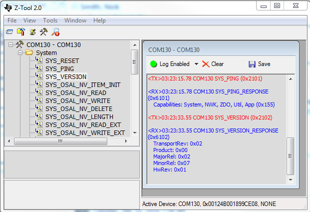
Therefore the default configuration is 115200 baud with no flow or parity, one stop bit, and 8 data bits. You can test the MT setup by opening Z-Tool and connecting to the device’s enumerated Application/UART COM Port by going to Tools → Settings → Serial Devices, double-clicking on the correct COM Port Name, and modifying the Port Settings as described above. You should then see the device recognized in the log window and be able to send a SYS_PING or SYS_VERSION message. Receiving a valid response confirms proper initialization. Please reference the Z-Stack Monitor and Test API for more information on how to utilize the MT interface.