

|
|
I2S driver implementation for a CC26XX I2S controller.
============================================================================
The I2S driver is unable to access flash memory in the address range 0x0000 - 0x2000 on devices based on the Cortex M33+ core (CC26X3/CC26X4) due to security constraints.
Only the following memory lengths are supported:
Some attributes in the I2S_Params structure have a limited set of supported values. These limitations are described below:
This section describes the structure and requirements for the sample buffers used in the I2S_Transaction objects.
Sample words are read from or written to the sample buffers in little-endian byte order, meaning that the least significant byte (LSByte) is stored at the lower byte address, and the most significant byte (MSByte) is stored at the higher byte address.
The sample buffers are divided into frames which are further subdivided into channels, and if a channel is used by both SD0 and SD1 (where the direction of the two pins are the same), then that channel is further subdivided into a sample word for first SD0 and then SD1.
The size of the buffers used in I2S_Transaction objects must be an even multiple of the number of bytes per frame. I.e. the number of bytes in the buffers must be of the form: 2*n*k, where k is the size of a frame in bytes and n is an integer satisfying n>=2. 2*n is the number of frames in the buffer.
Below code describes the general structure of a sample buffer if SD0 and SD1 are configured to the same direction.
Notes:
SD0_USE_CHANNEL_n should be true if SD0 uses channel n, otherwise false.SD1_USE_CHANNEL_n should be true if SD1 uses channel n, otherwise false.BYTES_PER_WORD is based on the configured memory length:
FRAMES_PER_BUFFER must be divisible by 2sampleBufferFrames needs to be cast to an uint8_t pointer to be used with the I2S driver.If SD0 and SD1 are not configured to the same direction (or only one is used) then the structure can be simplified as below:
Notes:
USE_CHANNEL_n should be true if channel n is used, otherwise false.If for example SD0 and SD1 are configured to the same direction and if channel 0 and 1 are used for SD0 and channel 0 is used for SD1, then the sample buffer would be structured as in the code below.
#include <ti/drivers/I2S.h>#include <ti/drivers/dpl/SemaphoreP.h>#include <ti/drivers/dpl/HwiP.h>#include <ti/drivers/Power.h>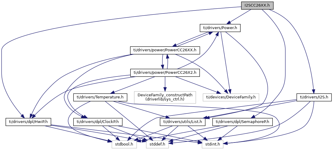
Go to the source code of this file.
Data Structures | |
| struct | I2SCC26XX_HWAttrs |
| I2S Hardware attributes. More... | |
Typedefs | |
| typedef void(* | I2SCC26XX_PtrUpdate) (I2S_Handle handle, I2SCC26XX_Interface *interface) |
| The definition of a function used by the I2S driver to refresh the pointer. More... | |
| typedef void(* I2SCC26XX_PtrUpdate) (I2S_Handle handle, I2SCC26XX_Interface *interface) |
The definition of a function used by the I2S driver to refresh the pointer.
| I2S_Handle | I2S_Handle |
| I2SCC26XX_Interface | *interface Pointer on the interface to update |