

|
|
General Purpose I/O driver interface.
The GPIO header file should be included in an application as follows:
The GPIO module allows you to manage General Purpose I/O pins via simple and portable APIs. GPIO pin behavior is usually configured statically, but can also be configured or reconfigured at runtime.
Because of its simplicity, the GPIO driver does not follow the model of other TI-RTOS drivers in which a driver application interface has separate device-specific implementations. This difference is most apparent in the GPIOxxx_Config structure, which does not require you to specify a particular function table or object.
This section provides a basic usage summary and a set of examples in the form of commented code fragments. Detailed descriptions of the GPIO APIs and their effect are provided in subsequent sections.
Creating an input callback: The following example demonstrates how to configure a GPIO pin to generate an interrupt and how to toggle an an LED on and off within the registered interrupt callback function. Pin configuration is handled within Sysconfig for this example.
Runtime pin configuration: The following example demonstrates how to (re)configure GPIO pins.
In order to use the GPIO APIs, the application is required to provide 3 structures in the ti_drivers_config.c file:
GPIO_init() must be called before any other GPIO APIs. This function configures each GPIO pin in the user-provided GPIO_PinConfig array according to the defined settings. The user can also reconfigure a pin dynamically after GPIO_init() is called by using the GPIO_setConfig(), and GPIO_setCallback() APIs.
GPIO_init() is called from Board_init() by default. Calling GPIO_init() multiple times is safe.
Unlike most other TI-RTOS drivers, there is no notion of an instance 'handle' with the GPIO driver. This allows lightweight pin control with minimal runtime and memory overhead.
GPIO pins are always referenced by device DIO index.
#include <stdint.h>#include <ti/devices/DeviceFamily.h>#include <ti/drivers/gpio/GPIOCC26XX.h>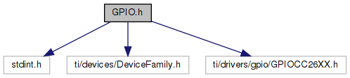
Go to the source code of this file.
Data Structures | |
| struct | GPIO_Config |
| GPIO driver configuration structure. More... | |
Macros | |
| #define | GPIO_PIN_TO_MASK(pin) (1 << (pin)) |
| #define | GPIO_INVALID_INDEX 0xFF |
| Dummy value for "this pin is not assigned to a GPIO". More... | |
GPIO_STATUS_* macros are general status codes returned by GPIO driver APIs. | |
| #define | GPIO_STATUS_SUCCESS (0) |
| Successful status code returned by GPIO_setConfig(). More... | |
| #define | GPIO_STATUS_ERROR (-1) |
| Generic error status code returned by GPIO_setConfig(). More... | |
GPIO_PinConfig output pin configuration macros | |
| #define | GPIO_CFG_OUTPUT |
| #define | GPIO_CFG_OUT_STD |
| #define | GPIO_CFG_OUT_OD_NOPULL |
| #define | GPIO_CFG_OUT_OD_PU |
| #define | GPIO_CFG_OUT_OD_PD |
| #define | GPIO_CFG_OUT_STR_LOW |
| #define | GPIO_CFG_OUT_STR_MED |
| #define | GPIO_CFG_OUT_STR_HIGH |
| #define | GPIO_CFG_OUT_HIGH |
| #define | GPIO_CFG_OUT_LOW |
GPIO_PinConfig input pin configuration macros | |
| #define | GPIO_CFG_INPUT |
| #define | GPIO_CFG_IN_NOPULL |
| #define | GPIO_CFG_IN_PU |
| #define | GPIO_CFG_IN_PD |
GPIO_PinConfig nondirectional pin configuration macros | |
| #define | GPIO_CFG_NO_DIR |
GPIO_PinConfig pin inversion configuration macros | |
| #define | GPIO_CFG_INVERT_OFF |
| #define | GPIO_CFG_INVERT_ON |
GPIO_PinConfig pin hysteresis configuration macros | |
| #define | GPIO_CFG_HYSTERESIS_OFF |
| #define | GPIO_CFG_HYSTERESIS_ON |
GPIO_PinConfig slew rate configuration macros | |
| #define | GPIO_CFG_SLEW_NORMAL |
| #define | GPIO_CFG_SLEW_REDUCED |
GPIO_PinConfig interrupt configuration macros | |
| #define | GPIO_CFG_IN_INT_NONE |
| #define | GPIO_CFG_IN_INT_FALLING |
| #define | GPIO_CFG_IN_INT_RISING |
| #define | GPIO_CFG_IN_INT_BOTH_EDGES |
| #define | GPIO_CFG_IN_INT_LOW |
| #define | GPIO_CFG_IN_INT_HIGH |
| #define | GPIO_CFG_INT_DISABLE |
| #define | GPIO_CFG_INT_ENABLE |
GPIO_Mux configuration macros | |
For additional muxing options, see the directions in the device-specific GPIO driver. | |
| #define | GPIO_MUX_GPIO |
Typedefs | |
| typedef uint32_t | GPIO_PinConfig |
| GPIO pin configuration settings. More... | |
| typedef void(* | GPIO_CallbackFxn) (uint_least8_t index) |
| GPIO callback function type. More... | |
Functions | |
| void | GPIO_clearInt (uint_least8_t index) |
| Clear a GPIO pin interrupt flag. More... | |
| void | GPIO_disableInt (uint_least8_t index) |
| Disable a GPIO pin interrupt. More... | |
| void | GPIO_enableInt (uint_least8_t index) |
| Enable a GPIO pin interrupt. More... | |
| void | GPIO_init (void) |
| Initializes the GPIO module. More... | |
| uint_fast8_t | GPIO_read (uint_least8_t index) |
| Reads the value of a GPIO pin. More... | |
| void | GPIO_toggle (uint_least8_t index) |
| Toggles the current state of a GPIO. More... | |
| void | GPIO_write (uint_least8_t index, unsigned int value) |
| Writes the value to a GPIO pin. More... | |
| void | GPIO_setCallback (uint_least8_t index, GPIO_CallbackFxn callback) |
| Bind a callback function to a GPIO pin interrupt. More... | |
| GPIO_CallbackFxn | GPIO_getCallback (uint_least8_t index) |
| Gets the callback associated with a GPIO pin. More... | |
| int_fast16_t | GPIO_setConfig (uint_least8_t index, GPIO_PinConfig pinConfig) |
| Configure the gpio pin. More... | |
| void | GPIO_setInterruptConfig (uint_least8_t index, GPIO_PinConfig config) |
| Configure the gpio pin. More... | |
| void | GPIO_getConfig (uint_least8_t index, GPIO_PinConfig *pinConfig) |
| Get the current configuration for a gpio pin. More... | |
| void | GPIO_resetConfig (uint_least8_t index) |
| Resets the configuration for a gpio pin to the default value. More... | |
| void | GPIO_setMux (uint_least8_t index, uint32_t mux) |
| Sets the mux for a gpio pin. More... | |
| uint32_t | GPIO_getMux (uint_least8_t index) |
| Get the current mux for a gpio pin. More... | |
| void | GPIO_setUserArg (uint_least8_t index, void *arg) |
| Set the user argument for a gpio pin. More... | |
| void * | GPIO_getUserArg (uint_least8_t index) |
| Get the user argument for a gpio pin. More... | |
| #define GPIO_PIN_TO_MASK | ( | pin | ) | (1 << (pin)) |
| #define GPIO_STATUS_SUCCESS (0) |
Successful status code returned by GPIO_setConfig().
GPI_setConfig() returns GPIO_STATUS_SUCCESS if the API was executed successfully.
| #define GPIO_STATUS_ERROR (-1) |
Generic error status code returned by GPIO_setConfig().
GPI_setConfig() returns GPIO_STATUS_ERROR if the API was not executed successfully.
| #define GPIO_INVALID_INDEX 0xFF |
Dummy value for "this pin is not assigned to a GPIO".
Not for use in customer software. Some drivers use this value to manage the behaviour of optional pins (e.g. UART flow control, SPI chip select). If you pass this value to any GPIO methods, it will return immediately and no register writes will be performed.
| typedef uint32_t GPIO_PinConfig |
GPIO pin configuration settings.
The meaning of the bits within PinConfig are entirely device-specific and are typically one-to-one with the hardware register controlling pin configuration.
Only create and manipulate these values using GPIO_CFG_* defines.
| typedef void(* GPIO_CallbackFxn) (uint_least8_t index) |
GPIO callback function type.
| index | GPIO index. This is the same index that was passed to GPIO_setCallback(). This allows you to use the same callback function for multiple GPIO interrupts, by using the index to identify the GPIO that caused the interrupt. |
| void GPIO_clearInt | ( | uint_least8_t | index | ) |
Clear a GPIO pin interrupt flag.
Clears the GPIO interrupt for the specified index.
Note: It is not necessary to call this API within a callback assigned to a pin. The driver clears interrupt flags before dispatching callbacks.
| index | GPIO index |
| void GPIO_disableInt | ( | uint_least8_t | index | ) |
Disable a GPIO pin interrupt.
Disables interrupts for the specified GPIO index.
| index | GPIO index |
| void GPIO_enableInt | ( | uint_least8_t | index | ) |
Enable a GPIO pin interrupt.
Enables GPIO interrupts for the selected index to occur.
Note: Prior to enabling a GPIO pin interrupt, make sure that a corresponding callback function has been provided. Use the GPIO_setCallback() API for this purpose at runtime. Alternatively, the callback function can be statically configured in the GPIO_CallbackFxn array provided.
| index | GPIO index |
| void GPIO_init | ( | void | ) |
Initializes the GPIO module.
The pins defined in the application-provided GPIO_config structure are initialized accordingly.
| uint_fast8_t GPIO_read | ( | uint_least8_t | index | ) |
Reads the value of a GPIO pin.
The value returned will either be zero or one depending on the state of the pin.
| index | GPIO index |
| void GPIO_toggle | ( | uint_least8_t | index | ) |
Toggles the current state of a GPIO.
| index | GPIO index |
| void GPIO_write | ( | uint_least8_t | index, |
| unsigned int | value | ||
| ) |
Writes the value to a GPIO pin.
| index | GPIO index |
| value | must be either 0 or 1 |
| void GPIO_setCallback | ( | uint_least8_t | index, |
| GPIO_CallbackFxn | callback | ||
| ) |
Bind a callback function to a GPIO pin interrupt.
Associate a callback function with a particular GPIO pin interrupt.
Callbacks can be changed at any time, making it easy to switch between efficient, state-specific interrupt handlers.
Note: The callback function is called within the context of an interrupt handler.
Note: This API does not enable the GPIO pin interrupt. Use GPIO_enableInt() and GPIO_disableInt() to enable and disable the pin interrupt as necessary, or use GPIO_CFG_INT_ENABLE when calling setConfig.
Note: it is not necessary to call GPIO_clearInt() within a callback. That operation is performed internally before the callback is invoked.
| index | GPIO index |
| callback | address of the callback function |
| GPIO_CallbackFxn GPIO_getCallback | ( | uint_least8_t | index | ) |
Gets the callback associated with a GPIO pin.
| index | GPIO index |
| int_fast16_t GPIO_setConfig | ( | uint_least8_t | index, |
| GPIO_PinConfig | pinConfig | ||
| ) |
Configure the gpio pin.
Dynamically configure a gpio pin to a device specific setting. For many applications, the pin configurations provided in the static GPIO_PinConfig array is sufficient.
For input pins with interrupt configurations, a corresponding interrupt object will be created as needed.
| index | GPIO index |
| pinConfig | device specific pin configuration settings |
| void GPIO_setInterruptConfig | ( | uint_least8_t | index, |
| GPIO_PinConfig | config | ||
| ) |
Configure the gpio pin.
Dynamically configure a gpio pin to a device specific setting. This variant only allows configuring the interrupt settings (rising edge, falling edge, etc.) and enabling or disabling interrupts.
Only GPIO_CFG_IN_INT_XXX macros and GPIO_CFG_INT_ENABLE/DISABLE may be passed to the config parameter for this function. If you do not pass GPIO_CFG_INT_ENABLE, this function will disable interrupts.
| index | GPIO index |
| config | pin configuration settings |
| void GPIO_getConfig | ( | uint_least8_t | index, |
| GPIO_PinConfig * | pinConfig | ||
| ) |
Get the current configuration for a gpio pin.
GPIO_getConfig() gets the current pin configuration.
This value may not be identical to the value used in setConfig, as some configuration options are applied directly to hardware on some devices and not saved in order to save memory.
| index | GPIO index |
| pinConfig | Location to store device specific pin configuration settings |
| void GPIO_resetConfig | ( | uint_least8_t | index | ) |
Resets the configuration for a gpio pin to the default value.
The default pin configuration is provided in the static GPIO_PinConfig array, defined by sysconfig or the board file at compile time. Also clears the callback and user argument.
This function is not supported on CC32XX devices.
| index | GPIO index |
| void GPIO_setMux | ( | uint_least8_t | index, |
| uint32_t | mux | ||
| ) |
Sets the mux for a gpio pin.
The procedure for muxing differs across devices, but this is the process of telling the hardware what function a given pin should perform. GPIO_setConfig() always configures pins as general purpose IO, but many peripherals require alternative settings.
For details and valid mux options, see the device-specific header file.
| index | GPIO index |
| mux | Device-specific mux value to use a special mode, or GPIO_MUX_GPIO to reset the pin to standard IO. |
| uint32_t GPIO_getMux | ( | uint_least8_t | index | ) |
Get the current mux for a gpio pin.
For details and valid mux options, see the device-specific header file.
| index | GPIO index |
| void GPIO_setUserArg | ( | uint_least8_t | index, |
| void * | arg | ||
| ) |
Set the user argument for a gpio pin.
This can be retrieved using GPIO_getUserArg() and can be helpful to share callback logic across different pins.
| index | GPIO index |
| arg | Pointer to a user object |
| void* GPIO_getUserArg | ( | uint_least8_t | index | ) |
Get the user argument for a gpio pin.
| index | GPIO index |