## Introduction
<br/>
Welcome to the MCU+ Academy - UDMA Driver Chapter.
In this chapter we will learn ways to utilize the UDMA Driver to perform various types of memory copies. All software
examples shown here are provided as part of the MCU+ SDK. The chapter starts with performing a simple data copy from
within an MCU+ SDK application. Next the chapter will continue with a CPU triggered transfer example suitable for low
latency transfers.
<!-- Then an advanced section will further demonstrate how to utilize additional features of the AM64x / AM243x Data Movement Subsystem and UDMA driver. -->
The UDMA Driver is the interface to the AM64x / AM243x DMSS (Data Movement Subsystem) as well as the NAVSS in other Sitara &
Jacinto processor families - although this chapter only focuses on the DMSS. To perform memory copies between two memory mapped
addresses we use the BCDMA (Block Copy DMA). The BCMDA programming model depends on building transfer parameters in to a
transfer request (TR). The transfer request is packaged in to a transfer request packet descriptor (TRPD) stored in shared
memory. Once the TRPD is built, a pointer to this transfer request is submitted to the DMSS and picked up for processing by
the BCDMA.
The software examples mentioned in this chapter can be referenced
<a href="https://dev.ti.com/tirex/explore/node?node=AHw3iwPFbtKev6QlCfxplg__rN4Qml4__LATEST">at this link</a>.
<br/>
<hr>
## Introduction to Terminology
<br/>
* Data Movement Subsystem (DMSS): container grouping together components which facilitate Direct Memory Access
* Block Copy DMA (BCDMA): copies data from a memory mapped source address to a memory mapped destination
* Ring Accelerator (RA): implements a queue in hardware for passing data between a producer and consumer in memory
* Transfer Request Record (TR): a data structure containing flags, loop counts, and other parameters for a transfer request
* Transfer Request Packet Descriptor (TRPD): a data structure containing a header and array of Transfer Request Records
* Forward Queue (FQ): the logical queue used by a processor core to submit a TRPD to the BCDMA
* Interrupt Aggregator (IA): module which converts between internal DMSS 'global events' and SoC-level interrupts
* Global Events: data completion or ring error events which get broadcast on a bus internal to the DMSS
* Local Events: these are interrupts generated from SoC modules which go to the Interrupt Aggregator (IA)
* Virtual Interrupts (VINT): Global or Local Events get assigned to VINTs which then go from IA to processors
<br/>
### Additional DMA Resources
<br/>
<!-- An appendix of information is available at the end of this module. -->
An API Guide for the UDMA Chapter is available in <a href="udma_driver.html#additional-reading">Additional Reading</a> below.
<!-- Refer to the **Data Movement Architecture Overview** chapter in the **AM64x Technical Reference Manual** for detailed information. -->
<br/>
<hr>
## Introduction to Transfer Request Records (TR)
<br/>
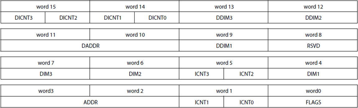
Note: all **ICNT** are 16-bit unsigned and all **DIM** are 32-bit signed
<br/>
### Transfer Request Parameters
**FLAGS**: specify type of TR, input triggers, and output events
**Source** Data Parameters
* **ADDR**: starting address of the source data
* **ICNT0**: loop count for level 0, number of bytes
* **ICNT1/2/3**: loop count for level 1, 2, 3, respectively
* **DIM1/2/3**: offsets, or stride, for loop level 1, 2, 3
**Destination** Data Parameters
* **DADDR**: starting address of the source data
* **DICNT0**: loop count for level 0, number of bytes
* **DICNT1/2/3**: loop count for level 1, 2, 3, respectively
* **DDIM1/2/3**: offsets, or stride, for loop level 1, 2, 3
<br/>
<hr>
## Data Movement Subsystem Interaction
<br/>
<br>
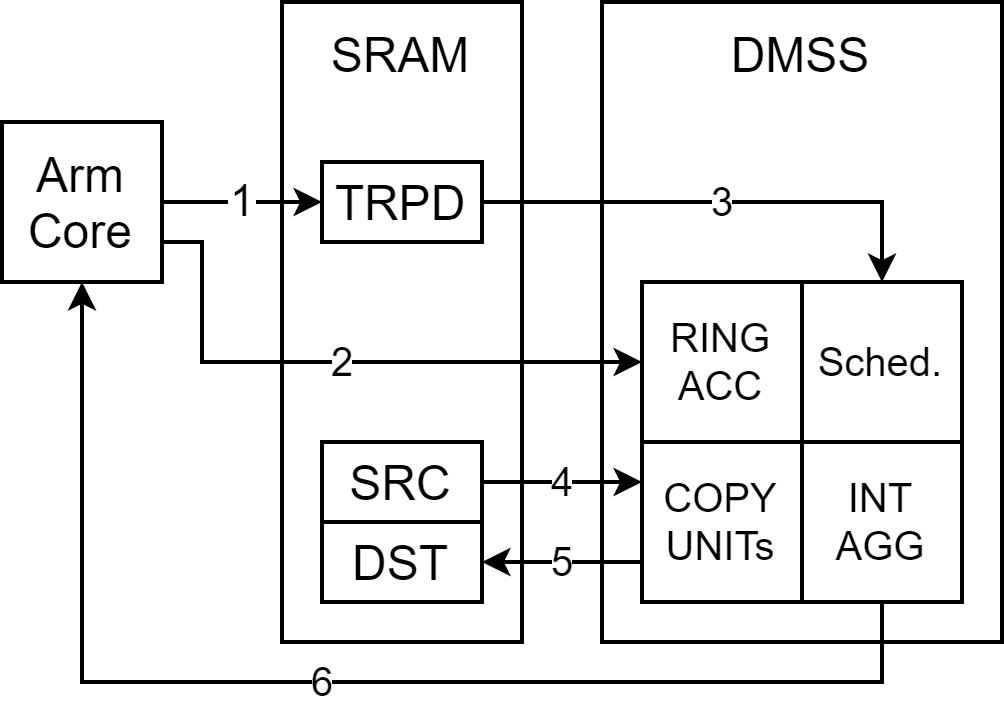
1. Allocate memory for the TRPD. Write desired TR parameters to the data structure.
2. Push TRPD memory pointer on to the ring accelerator forward queue.
3. BCDMA will read TR parameters from TRPD and the scheduler will begin.
4. BCDMA will read data.
5. BCDMA will write data.
6. A registered callback function will run upon TR completion event.
<br/>
<hr>
## Integration to System Config
<br/>
<br>
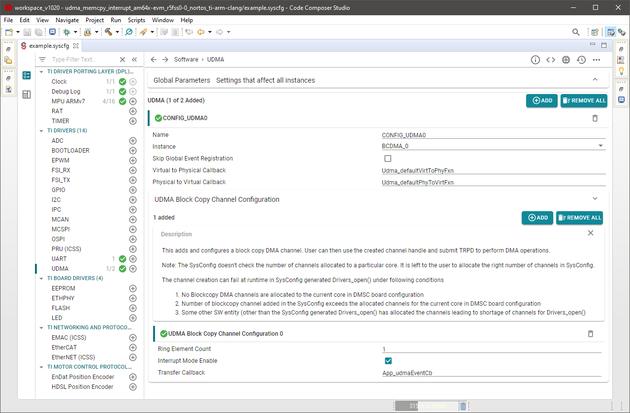
Adding the UDMA Driver to an MCU+ SDK application can be done using the SysConfig interface.
1. Add a new UDMA config and select BCDMA_0 as the DMA instance.
2. Expand the UDMA Block Copy Channel Configuration menu and add as many channels as necessary.
4. (Optional) To enable a DMA completion interrupt check the box for Interrupt Mode Enable.
If Interrupt Mode Enable is checked then you may provide System Config with the name of the callback function used in your
application. Two examples are provided `udma_memcpy_interrupt` and `udma_memcpy_polling` to demonstrate the differences.
System Config will auto generate code depending on your entries in the interface. After initialization your application will
have an array of channel handles ready to be used.
<br/>
<hr>
## Basic Memcpy Example
<br/>
UDMA Memcpy can be used with either FreeRTOS or NoRTOS.
The SDK provides a `udma_memcpy_interrupt` or `udma_memcpy_polling` example that demonstrates a simple copy of 1024 bytes
from one memory location to another memory location. The function `App_udmaTrpdInit()` is used to build the transfer request
(`pTR`) and transfer request packet descriptor (`trpdMem`). The flags given in this function can be considered the default
parameters for a basic memcpy operation. When the trpdMem pointer is submitted to the ring accelerator queue the transfer
request will execute immediately. See the next example `udma_sw_trigger` on how to queue a transfer request which can stay
idle until it becomes triggered later.
#### TR Flags
* EVENT_SIZE flag set to EVENT_SIZE_COMPLETION: the transfer request returns an event when all loops complete.
* TRIGGER0 and TRIGGER1 flags both set to NONE: transfer request runs immediately once submitted to the queue.
#### TR Parameters
* Parameters ICNT0 and DICNT0 are set to `length` bytes
* Remaining ICNT1,2,3 and DICT1,2,3 are set to 1
* Parameters DIM1,2,3 and DDIM1,2,3 are set based on ICNT0,1,2 and DICNT0,1,2 for a standard memcpy.
<br/>
<hr>
## CPU Triggered Example
<br/>
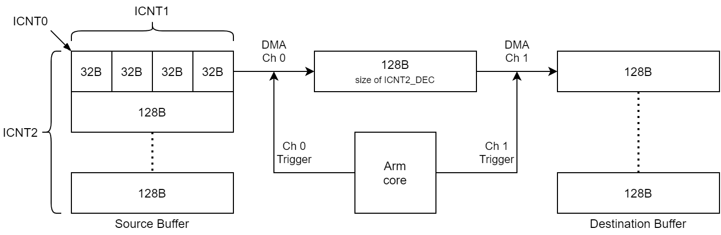
The SDK provides a `udma_sw_trigger` example that demonstrates a more complex copy of 1280 bytes in total. However, in this case the
transfer is done 128 bytes at a time. Two DMA channels are enabled: the first channel is used to transfer 128 bytes at a time from the
source buffer to a middle "indirect" buffer while the second channel transfers 128 bytes at a time from the middle "indirect" buffer to
the destination buffer. The CPU is responsible for sending an event to each channel to initiate the transfers. It will trigger channel 0
first to transfer 128 bytes in to the indirect buffer then it will trigger channel 1 to transfer the 128 bytes out of the indirect buffer
to the destination buffer.
<br/>
<br>
The function `App_udmaTrpdInit()` is used to build the transfer request (`pTR`) and transfer request packet descriptor (`trpdMem`). The
flags given in this function are changed from default parameters described before in the basic memcpy operation.
#### TR Flags for both Channels
* EVENT_SIZE flag changed to EVENT_SIZE_ICNT2_DEC: the transfer will generate an event for each decrement of ICNT2.
* TRIGGER0 flag set to GLOBAL0: the transfer will start when the channel's global event 0 is received
* TRIGGER0_TYPE set to ICNT2_DEC: the transfer run until ICNT2 decrements for each trigger 0 received.
* TRIGGER1 flag set to NONE: the second TR trigger option is not used and so TRIGGER1_TYPE is not used.
<br>
#### TR Parameters Common to both Channels
* ICNT0 and DICNT0 are set to 32 bytes
* ICNT1 and DICNT1 are set to 4
* ICNT2 and DICNT2 are set to 10
The TR flags dictate that for every event received on a channel the TR will run until ICNT2 decrements by one resulting in ICNT0 x ICNT1
bytes copied. This example will send trigger events to the channels ICNT2 times for a total of ICNT0 x ICNT1 x ICNT2 bytes copied by the
end of this TR.
<br>
#### TR Parameters for Source to Indirect Buffer Copy
* DIM1 is set to 32 bytes (size of ICNT0)
* DIM2 is set to 128 bytes (size of ICNT0 x ICNT1)
* DIM3 is set to 1280 bytes (size of ICNT0 x ICNT1 x ICNT2)
* DDIM1 is set to 32 bytes (size of DICNT0)
* DDIM2 and DDIM3 are set to 0 bytes
The source address pointer will advance by DIM1 bytes for every ICNT1 loop, by DIM2 bytes for every ICNT2 loop, and by DIM3 bytes for every
ICNT3 loop. The one-to-one addressing means the TR source address pointer will advance forward through the 1280 byte buffer linearly. This
part of the TR configuration is identical to the previous memcpy example. For the destination address pointer it will advance by DDIM1 bytes
for every DICNT1 loop. Therefore the destination address will advance by 32 bytes (DDIM1) for 4 times (DICNT1) and copy 128 bytes to the
indirect buffer. With DDIM2 set to 0 then the destination address pointer will reset to the start of the indirect buffer for every ICNT2 loop.
All 1280 bytes on the source side will be copied to the indirect buffer 128 bytes at a time overwriting the previous data.
<br>
#### TR Parameters for Indirect Buffer to Destination Copy
* DIM1 is set to 32 bytes (size of ICNT0)
* DIM2 and DIM3 are set to 0 bytes
* DDIM1 is set to 32 bytes (size of DICNT0)
* DDIM2 is set to 128 bytes (size of DICNT0 x DICNT1)
* DDIM3 is set to 1280 bytes (size of DICNT0 x DICNT1 x DICNT2)
These parameters will be the inverse operation to unpack data from the 128 byte indirect buffer to the 1280 byte destination buffer.
<br/>
<hr>
## []{ } Knowledge Check
<br>
**1.** Up to how many loop levels, or dimensions, can be defined in a single transfer request (TR)?
[quiz]
v Four --> Correct! A TR will transfer ICNT0 x ICNT1 x ICNT2 x ICNT3 bytes
x Three --> Incorrect
x Two --> Incorrect
x One --> Incorrect
[quiz]
<br>
**2.** What is the maximum value that can be set in any ICNTx or DICNTx field?
[quiz]
x 16,000 --> Incorrect
x 32,000 --> Incorrect
v 65,535 --> Correct! 16-bit unsigned represents up to 2^16-1
x 65,536 --> Incorrect
[quiz]
<br>
**3.** If the TRIGGER0 and TRIGGER1 flags in a transfer request (TR) are set to NONE then how will that affect the DMA behavior?
[quiz]
x The TR will never run if no trigger is defined --> Incorrect
v The TR will run as soon as it is queued --> Correct!
[quiz]
<br/>
**4.** In the software triggered example, what method is used to trigger the DMA channel?
[quiz]
x A timer is software configured to interrupt the DMA --> Incorrect
x The CPU uses the Interrupt Aggregator to interrupt the DMA --> Incorrect
v The CPU writes to a channel dedicated register --> Correct!
[quiz]
<br/>
<hr>
## Congratulations!
<br/>
Now you may pat yourself on the back! You have learned enough about the UDMA Driver to add it to an MCU+ SDK application and perform memory
copies driven by software.
<br/>
<hr>
## Additional Reading
<br/>
##### MCU+ SDK API Guide: [UDMA Driver](https://software-dl.ti.com/mcu-plus-sdk/esd/AM243X/latest/exports/docs/api_guide_am243x/DRIVERS_UDMA_PAGE.html)
##### MCU+ Academy: [SysConfig Overview](sysconfig.html)
##### MCU+ Academy: [FreeRTOS Kernel](freertos.html)
<br/>
<hr>
{{r> [Back to Home](../overview.html)}}
{{r **Was this helpful? Let us know here:** [mcu_plus_academy_feedback@list.ti.com](mailto:mcu_plus_academy_feedback@list.ti.com)}}
<div align="center" style="margin-top: 4em; font-size: smaller;">
<a rel="license" href="https://creativecommons.org/licenses/by-nc-nd/4.0/"><img alt="Creative Commons License"
style="border-width:0" src="..//web_support/cc_license_icon.png" /></a><br />This work is licensed under a <a
rel="license" href="https://creativecommons.org/licenses/by-nc-nd/4.0/">Creative Commons
Attribution-NonCommercial-NoDerivatives 4.0 International License</a>.</div>