DRV8311HEVM Hardware User Guide
1. Overview
To spin the BLDC motor with the DRV8311HEVM, the user needs to modify some jumpers on the MSPM0 LaunchPad, connect the EVM pins to the LaunchPad, connect the motor phases and hall sensors to the DRV hardware and power on the supply.
2. Hardware Required
LP-MSPM0G3507 - MSPM0G3507 Launchpad
DRV8311HEVM - DRV8311HEVM evaluation module
DC Power supply that supports the required voltage and current
BLDC Motor
Micro-USB cable
3. Hardware Setup
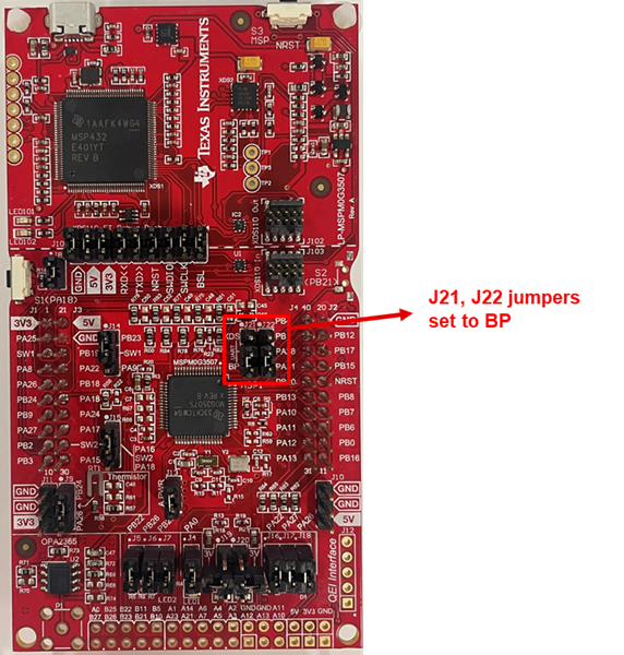
Connect the jumpers J21 and J22 on the LP-MSPM0G3507 to the BP position
If using external ADC reference, populate resistor R22 on the LP-MSPM0G3507 and apply the external reference voltage to PA23, which is accessible on the bottom header row of the Launchpad.
Connect the LP-MSPM0G3507 to the DRV8311HEVM using jumper wires as shown in the table below. Refer to the schematic connector pinout for the locations of the DRV8311HEVM signals.

Connection
MSPM0G3507
DRV8311HEVM
Jumper Notes
Phase A HS input
PB4
INHA
Phase A LS input
PB1
INLA
Phase B HS input
PA28
INHB
Phase B LS input
PA31
INLB
Phase C HS input
PB20
INHC
Phase C LS input
PB13
INLC
HALL A input
PA10
HALLA
J21 connected to BP
HALL B input
PA11
HALLB
J22 connected to BP
HALL C input
PA12
HALLC
Bus voltage input
PA25
VSENVM
Phase A voltage
PB19
VSENA
Phase B voltage
PA22
VSENB
Phase C voltage
PB18
VSENC
Phase A current
PA24
ISENA
Phase B current
PA17
ISENB
Phase C current
PA18
ISENC
DRV fault input
PB12
nFAULT
DRV sleep input
PB2
nSLEEP
Ground
GND
AGND
Connect the 3 phases of the motor to OUTA, OUTB, and OUTC of the motor connector terminal block on the DRV8311HEVM and the HALLA/B/C, Hall power, and Hall GND signals to the Hall connector block. Note: The user should identify the correct phases of motor from motor datasheets, this will vary from motor to motor.
Connect the positive and negative of the power supply to VM and PGND/AGND of the power connector terminal block to the DRV8311HEVM. Don’t turn on the power supply output.
Connect a Micro-USB cable from the LP-MSPM0G3507 to the PC.
Set the power supply to a motor voltage within the DRV8311 specifications. Turn on the power supply. The green VM LED on the DRV8311HEVM should turn on.
Once all the setup is done, spin the motor using the software or GUI. Refer to Software User Guide or GUI User Guide for more details.