DRV8323 GUI User Guide
1. Overview
This graphical user interface (GUI) was developed to allow simple evaluation of a user’s motor with the BOOSTXL-DRV8323RH being controlled by TI’s MSPM0 microcontroller. This guide will go over the key parts of the GUI to allow you to get up and running quickly. You can access the GUI described in this document here.
1.1 Getting Started with GUI
The GUI allows the user to configure various settings required for BLDC motor control. The user can adjust settings like dutycycle, PWM Frequency, deadband, direction control, acceleration rate, ADC reference, fault status monitoring, speed monitoring.
1.2 Hardware Connection
Perform the following steps to begin using the GUI:
Connect the BLDC motor to the BOOSTXL-DRV8323RH.
Make the necessary connections for connecting LP-MSPM0G3507 to BOOSTXL-DRV8323RH.
Plug in the micro-USB cable to the PC.
Enable the power supply to EVM.
View the hardware user guide for detailed steps required to get the hardware in the right state to run this GUI example.
2. Using the GUI
The GUI will automatically program the LaunchPad with the necessary firmware. If everything is successful the bottom left corner of the GUI should say “Hardware connected”.

3. GUI Window
In the GUI window user can find various controls like ENABLE, Direction control, dutycycle, pwm frequency, deadband, and acceleration rate. Various faults are also indicated using LEDs.

3.1 Motor Control
Once the hardware connections are done and GUI is connected to device, the motor is ready to spin. All the controls are in defaults. The user can spin the motor by adjusting the duty cycle.

Function |
Default |
Description |
|---|---|---|
nSLEEP |
Awake |
Controls the DRV ENABLE pin and low power status and sets the duty cycle to zero |
Direction |
Reverse |
Controls the direction of motor spinning |
PWM Frequency |
20kHz |
PWM Frequency can be varied from 1kHz to 100kHz |
Deadband |
320ns |
Deadband can be varied from 100ns to 1000ns |
Duty cycle |
0% |
Minimum of 5 percent is applied to start spinning |
Acceleration rate |
20 |
Duty cycle is incremented or decremented at a rate of 1% per 20ms |
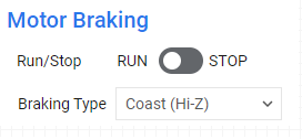
3.2 Motor Braking
The motor can be stopped from GUI without turning off the DRV by using stop button. The motor stops spinning with brake type selected.
Function |
Default |
Description |
|---|---|---|
Run/Stop |
Run |
Stops the motor according to the braking type |
Braking type |
Brake |
Braking type can be coast or brake. |
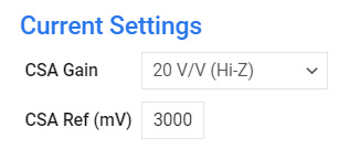
3.3 Current setting
The DRV8323 integrates three low side current sense amplifiers for current measurements. It has features like programmable gain and setting external references. Changing the CSA Gain will automatically update the DRV register.
Function |
Default |
Description |
|---|---|---|
CSA gain |
20V/V |
CSA gain can be set to 5, 10, 20, 40V/V using the GAIN resistor setting on the EVM |
CSA Vref |
3V |
External voltage reference for current monitoring. |
3.4 Fault Status
The firmware continuously monitors the motor parameters like voltage and current. The user can set the limits for voltage and current from GUI. When any of the faults occur the corresponding LED glows.
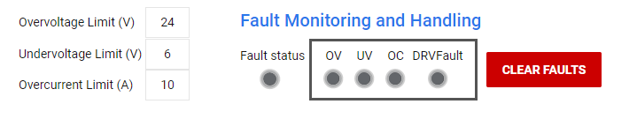
Fault |
Function |
Description |
|---|---|---|
UV |
Undervoltage fault |
LED glows when module voltage is less than undervoltage limit |
OV |
Overvoltage fault |
LED glows when module voltage is more than overvoltage limit |
OC |
Overcurrent fault |
LED glows when phase current is more than overcurrent limit |
DRV |
DRVFault |
LED glows when DRV generates a fault |
3.5 ADC Reference Setting
The user can use 3 different ADC references, it can be changed from GUI.

Function |
Default |
Description |
|---|---|---|
ADC VREF |
ADC Reference Voltage |
User reference voltage source of VDDA, internal reference, or external reference. |
INT VREF |
ADC VREF 2.5V |
Internal reference can be 2.5V or 1.4V |
EXT VREF |
3300mV |
User need to input the external reference voltage applied |
When VDDA is used as ADC reference the data input in internal reference and external reference is ignored.
3.6 Voltage and Current Monitoring
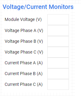

The user can monitor the motor parameters like bus voltage, phase voltages and phase currents. The user can see the bus voltage graph.
3.7 Speed Monitoring
When the motor starts spinning the user can see the motor speed displayed in RPM. The user needs to input the number of poles in the motor used. The user must enter even number of poles failing which the speed calculation go wrong.
