Introduction
This SimpleLink™ Academy lab will take you through the process of integrating an existing proprietary radio application alongside another radio protocol stack using DMM.
The Dynamic Multi-protocol Manager (DMM) allows multiple wireless stacks to coexist and operate concurrently on a single radio on a CC13x2 or CC26x2 device. DMM allows the user to define and control the priorities and timing constraints of each stack at run-time.
This lab will combine a proprietary collector example together with the BLE Simple Peripheral example. The proprietary collector example utilizes a custom synchronous time-slotted radio protocol which allows for a sleepy collector implementation. The user will be instructed on how to integrate DMM in regards to the policy table, global priority table, application states as well as how to transition between states in the application.
At the end of the lab, the user will have a DMM project featuring concurrent proprietary radio communication alongside an active BLE connection. While the lab can be completed using a single LaunchPad™, it is recommended to have at least two LaunchPads in order to setup the proprietary sensor/collector network.
Do not get confused!
While the proprietary examples uses the notion of "Sensor" and "Collector", this is not related to the TI 15.4-Stack Sensor and Collector.
This lab assumes the reader has basic knowledge about the TI BLE and DMM offering, as well as basic embedded programming skills.
Prerequisites
Other SimpleLink Academy Labs
- Completion of DMM Fundamentals
- Completion of BLE Fundamentals
- Completion of BLE Connections
Hardware
For the DMM device, 1x LaunchPad of:
For the RF Sensor device, 1x LaunchPad of
*A smart phone with a BLE explorer app
Note
The Proprietary RF Collector and Sensor examples are currently only supported for the CC1352R.
Software
- Code Composer Studio, version 9.2 or later with support for CC13xx/CC26xx devices
- SimpleLink CC13x2 / CC26x2 SDK, version 3.30 or later
- RF Collector and Sensor example matching the SDK version used.
Proprietary examples on GitHub
The Proprietary RF Collector and Sensor examples used in this lab are found on the proprietary examples GitHub repository and is not part of the official SDK. These examples need to be downloaded in addition to the SimpleLink CC13x2 / CC26x2 SDK.
Recommended reading
It is recommended to read the DMM User's Guide alongside this lab for details and further information.
Proprietary Collector and Sensor
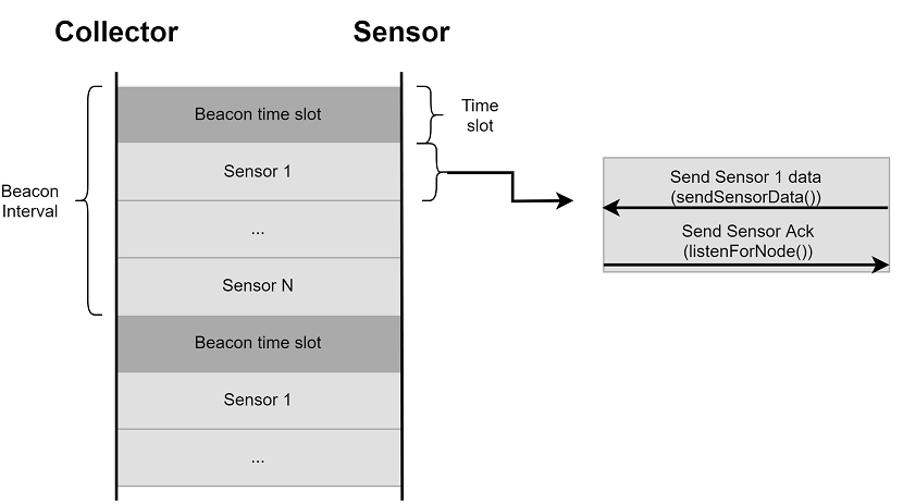
The Proprietary Collector and Sensor examples use a very simple time-slotted protocol to realize synchronous communication between a collector and multiple sensors without the need to keep the radio on at all times. Because the protocol uses fixed time-slots, there are time-slots which are potentially unused. This allows for collision-free access to the radio at certain time-slots for other concurrently running radio protocol stacks. This makes the collector and sensor examples a good fit for showcasing the different aspects of DMM and how to integrate this with existing proprietary solutions.
The collector and sensor operate inside a fixed time window, referred to in
the examples as the BEACON_INTERVAL. Once per time window the collector will
broadcast its existence for new sensors in order for them to join the network.
For the duration of the time window the collector will also communicate with
the sensors that are already connected, exchanging data at a given point in
time as illustrated in the image below.
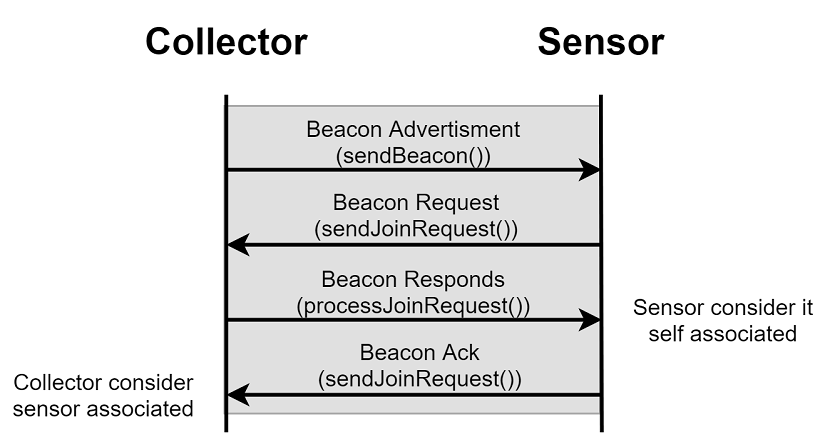
When a new sensor wants to join the network it listens for a beacon from the collector. When a beacon is received, the sensor may send a request to join the network back to the collector that issued the beacon. When the collector and sensor has acknowledged the request, the sensor will have joined the network and been assigned a time-slot. The full association sequence following a collector beacon is illustrated in the following sequence diagram:
Please refer to the README files for each project for more information.
Running the Examples
A great way to understand how the Proprietary Collector and Sensor examples work is to run them. Start by importing and building both the collector and sensor example from the GitHub repo. When both projects have been built, program the LaunchPads with one project each and let them run.
Both the collector and sensor will output information regarding the connection status over the LaunchPad's application UART port. The output can be seen by connecting to the LaunchPad's serial port using a terminal application, such as PuTTY.
The Sensor will output its device address, data, number of missed acknowledgements, and whether it is currently connected to a Collector or regarded as an orphan. Prior to any association both the "is connected" and "is orphan" labels will display false. Similarly, the Collector will display the status of all connected nodes from its terminal. Each node is referenced by its device address.
When a Sensor has formed an association to the Collector, it will be shown in both terminals. Per default, a sensor is considered an orphan following five unsuccessful communication exchanges with the collector.
Clock drift is not handled by the simple radio protocol. This means that the collector and sensor will drift apart and over time start to miss the time slots where they are supposed to meet. However, this sorts itself out when the Sensor is regarded as an orphan and will re-associate itself to the Collector.
When you feel familiarized with the Sensor and Collector applications, you can proceed with the lab.
Before you start
Before we start, create an empty CCS workspace and import the following examples projects:
simple_peripheral_app, found under<SDK>/examples/rtos/<BOARD>/ble5stack/rfCollector, found under<CLONED_REPO>/examples/rtos/<BOARD>/rfSensor, found under<CLONED_REPO>/examples/rtos/<BOARD>/
where <SDK> is the install location of the SimpleLink SDK, <CLONED_REPO> is
the location of the cloned proprietary_examples repo, and
<BOARD> must correspond to the board being used for that example project. When
all projects has been imported, build all projects and make sure that there are
no build errors.
Device terminology
From this point on, we will refer to the LaunchPad used for the DMM project as the "DMM device". The LaunchPad used with the RF Sensor will be referred to as the "Sensor device".
After building the simple_peripheral_app project, download it to the DMM
device and verify that it is working as expected. For more information on what
output to expect, see the BLE labs referenced under
[Prerequisites][#prerequisites].
When looking to integrate two existing protocols together using DMM it is
recommended to start with the more complex of the projects (in terms of
structure) as a base line. In this lab, the simple_peripheral_app example will
be used as the base line. The reason for integrating the rfCollector example
into the simple_peripheral_app example is because it requires less
modifications to the project than the other way around.
Task 1 – Prepare Project for DMM Integration
Time to prepare simple_peripheral_app for DMM integration.
Restructure CCS Project
The first step is to adjust the project folder structure for the additional
stack application and DMM. In the simple_peripheral_app project, do the
following:
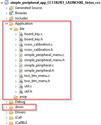
Add a new folder inside the
Application/folder and name itble/. We will put all BLE specific application files in this folder, which means move all existing files in theApplication/folder intoble/.Add a new folder inside the
Application/folder and name itprop/. We will put all Proprietary Collector specific application files in this folder, but we will do this later.Create a new top-level folder called
dmm/. We will put all DMM specific source files in this folder.
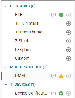
When you are done, your project explorer should look something like this:
In order for the project to find the recently added files, add the following include search paths in the project properties:
Navigate to
Project Properties→Build→ARM Compiler→Include Options.Add the following search paths:
${PROJECT_ROOT}/Application/ble${PROJECT_ROOT}/Application/prop${PROJECT_ROOT}/dmm
We need to add the USE_DMM define in order to enable DMM for TI source code:
Navigate to
Project Properties→Build→ARM Compiler→Predefined Symbols.Add the following pre-define symbol:
USE_DMM
The pre-compiled DMM library also needs to be included as part of the linker step:
Navigate to
Project Properties→Build→ARM Linker→File Search Path.Add the pre-compiled DMM library at the top in the Include library file view:
Library order matters
It is important the DMM library is added before the RF multi-mode library.
If you are compiling for a CC13x2 device:
${COM_TI_SIMPLELINK_CC13X2_26X2_SDK_INSTALL_DIR}/source/ti/dmm/library/tirtos/ccs/bin/dmmlib_cc13x2.a
If you are compiling for a CC26x2 device:
${COM_TI_SIMPLELINK_CC13X2_26X2_SDK_INSTALL_DIR}/source/ti/dmm/library/tirtos/ccs/bin/dmmlib_cc26x2.a
Add DMM Files
Now it is time to add the DMM files to the newly created dmm/ folder. Go to
the <SDK>/source/ti/dmm/ directory and copy the following files into the
project dmm/ folder:
dmm_rfmap.hdmm_policy.hdmm_scheduler.h
The DMM files do not require any modifications, but we need a policy table and a global priority table. We will generate the policy table with SysConfig, so no need to create any source files for that. However, we will be required to create the global priority table manually.
Create the Global Priority Table
There already exists pre-made global priority tables in the SDK for DMM examples, which consists of various stack combinations. One particularly is the BLE + WSN combination, which we can re-use for our purpose by replacing WSN with Proprietary stack.
Copy over the following files from <SDK>/source/ti/dmm/ to dmm/:
dmm_priority_ble_wsn.cdmm_priority_ble_wsn.h
Rename both files to dmm_priority_ble_prop, and rename all instances of
WSN to PROP in the source code. In addition, we will replace the existing
RF activities for WSN with Prop. These RF activities have already been defined
by the rfCollector example, as such:
RfActivity_Prop_Tx = 0x0A01RfActivity_Prop_Rx = 0x0A02RfActivity_Prop_Tx_Rx = 0x0A03
Note that the activity and the corresponding value is important to match. We
will also use the reserved1 stack role for the Proprietary stack. You
should end up with something like this:
//! \brief Activity numbers and priority numbers
#define ACTIVITY_NUM_BLE                        4
#define ACTIVITY_NUM_PROP                       3

extern GlobalTable globalPriorityTable[DMMPOLICY_NUM_STACKS];
dmm_priority_ble_prop.h
#include <dmm/dmm_priority_ble_prop.h>
#include "dmm/dmm_policy.h"

/* BLE Activity */
typedef enum
{
    /* ... unmodified ... */
} DMMStackActivityBLE;

typedef enum
{
    DMM_PROP_TX    = 0x0A01,
    DMM_PROP_RX    = 0x0A02,
    DMM_PROP_TX_RX = 0x0A03,
} DMMStackActivityPROP;

/* Global Priority Table: BLE connection lower than Prop data */

StackActivity activityBLE[ACTIVITY_NUM_BLE * PRIORITY_NUM] =
{
    /* ... unmodified ... */
};

StackActivity activityPROP[ACTIVITY_NUM_PROP * PRIORITY_NUM] =
{
    /* Activity order matters */
    DMM_GLOBAL_PRIORITY(DMM_PROP_TX, DMM_StackPNormal,  90),
    DMM_GLOBAL_PRIORITY(DMM_PROP_TX, DMM_StackPHigh,   180),
    DMM_GLOBAL_PRIORITY(DMM_PROP_TX, DMM_StackPUrgent, 240),

    DMM_GLOBAL_PRIORITY(DMM_PROP_RX, DMM_StackPNormal,  90),
    DMM_GLOBAL_PRIORITY(DMM_PROP_RX, DMM_StackPHigh,   180),
    DMM_GLOBAL_PRIORITY(DMM_PROP_RX, DMM_StackPUrgent, 240),

    DMM_GLOBAL_PRIORITY(DMM_PROP_TX_RX, DMM_StackPNormal,  90),
    DMM_GLOBAL_PRIORITY(DMM_PROP_TX_RX, DMM_StackPHigh,   180),
    DMM_GLOBAL_PRIORITY(DMM_PROP_TX_RX, DMM_StackPUrgent, 240),
};


/* the order of stacks in policy table and global table must be the same */
GlobalTable globalPriorityTable[DMMPOLICY_NUM_STACKS] =
{
    {
        .globalTableArray =  activityBLE,
        .tableSize = (uint8_t)(ACTIVITY_NUM_BLE * PRIORITY_NUM),
        .stackRole = DMMPolicy_StackRole_BlePeripheral,
    },

    {
        .globalTableArray =  activityPROP,
        .tableSize = (uint8_t)(ACTIVITY_NUM_PROP * PRIORITY_NUM),
        .stackRole = DMMPolicy_StackRole_reserved1,
    },
};
dmm_priority_ble_prop.c
This global priority table will prioritize Proprietary data over BLE connections.
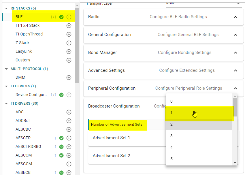
To further improve the final result, the BLE long-range advertisement set is disabled. This is done because the long-range communication takes up more radio time than legacy advertising. Since our project does not need to be a long-range application, the extra radio time can be freed up in favor of other commands. It is possible to use long- range, but it will impact the final performance.
To disable the second advertisement set, make the changes according to the snippets found in the following expansion:
First, disable the second advertisement set in SysConfig.
Then, comment out the configuration of said advertisement set in simple_peripheral.c.
        // Enable legacy advertising for set #1
        status = GapAdv_enable(advHandleLegacy, GAP_ADV_ENABLE_OPTIONS_USE_MAX , 0);
        SIMPLEPERIPHERAL_ASSERT(status == SUCCESS);

        /* Disable this chunk of code */
#if 0
        // Create Advertisement set #2 and assign handle
        status = GapAdv_create(&SimplePeripheral_advCallback, &advParams2,
                               &advHandleLongRange);
        SIMPLEPERIPHERAL_ASSERT(status == SUCCESS);

        // Load advertising data for set #2 that is statically allocated by the app
        status = GapAdv_loadByHandle(advHandleLongRange, GAP_ADV_DATA_TYPE_ADV,
                                     sizeof(advData2), advData2);
        SIMPLEPERIPHERAL_ASSERT(status == SUCCESS);

        // Set event mask for set #2
        status = GapAdv_setEventMask(advHandleLongRange,
                                     GAP_ADV_EVT_MASK_START_AFTER_ENABLE |
                                     GAP_ADV_EVT_MASK_END_AFTER_DISABLE |
                                     GAP_ADV_EVT_MASK_SET_TERMINATED);

        // Enable long range advertising for set #2
        status = GapAdv_enable(advHandleLongRange, GAP_ADV_ENABLE_OPTIONS_USE_MAX , 0);
        SIMPLEPERIPHERAL_ASSERT(status == SUCCESS);
#endif
simple_peripheral.c
Create the Policy Table
The policy table is configured in SysConfig. Open SysConfig by double clicking
simple_peripheral.syscfg.
Add the DMM component found under the Multi-Protocol section. Note that you will immediately get a warning, but we will fix this shortly.
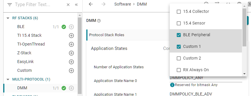
First set the stack roles to be BLE Peripheral and Custom 1. The Custom
1 stack role will correspond to the reserved1 stack role we used in the
global priority table.
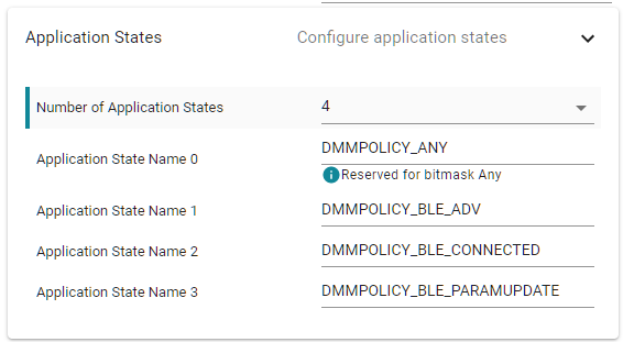
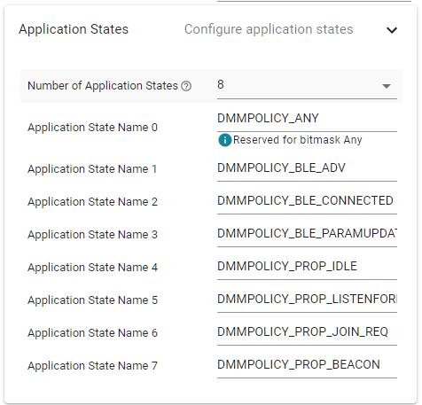
Next, we add the following application states for BLE. Note that the first application state is reserved for the Any application state, which is common for both stack roles.
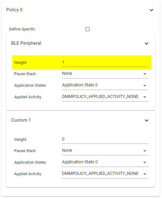
Lastly, in the policy table, there is already one DMM policy. This is the default policy, which we need to set one stack role with higher priority. This is the source of the warning we initially got, because the default policy is used as a tie breaker between both stack roles.
In this case, set BLE to be higher priority in a tie breaker by giving it a higher weight. Any number suffices. When set, the warning should disappear.
Initialize and use DMM in the Project
Now that the DMM source files and tables in place, the BLE application needs
to be modified to use DMM. We will start with initializing DMM and made aware
of the BLE stack. This means we need to do the following modifications to the
main.c file, found in the Startup/ folder:
Include the following header files at the top
dmm/dmm_policy.hdmm/dmm_scheduler.hdmm/dmm_priority_ble_prop.hti_dmm_application_policy.h
Initialize and open up the DMM Policy Manager using the policy table defined inside
ti_dmm_application_policy.hand the global priority table defined insidedmm_priority_ble_prop.h- Initialize and open up the DMM Scheduler
- Extract the BLE stack handle using
Icall_getRemoteTaskHandle(0)and register the client with the DMM Scheduler - Set the initial BLE Peripheral stack state to "Advertising"
Add the following changes inside main.c:
/*******************************************************************************
 * INCLUDES
 */

/* Include DMM module */
#include "dmm/dmm_policy.h"
#include "dmm/dmm_scheduler.h"
#include "dmm/dmm_priority_ble_prop.h"
#include "ti_dmm_application_policy.h"

int main()
{
    // =========== ADD START ===========
    Task_Handle* pBleTaskHndl;
    DMMPolicy_Params dmmPolicyParams;
    DMMSch_Params dmmSchParams;
    // =========== ADD END ===========

    ...

    /* Start tasks of external images - Priority 5 */
    ICall_createRemoteTasks();
    // =========== ADD START ===========
    pBleTaskHndl = ICall_getRemoteTaskHandle(0);
    // =========== ADD END ===========

    ...

    // =========== ADD START ===========
    /* initialize and open the DMM policy manager */
    DMMPolicy_init();
    DMMPolicy_Params_init(&dmmPolicyParams);
    dmmPolicyParams.numPolicyTableEntries = DMMPolicy_ApplicationPolicySize;
    dmmPolicyParams.policyTable = DMMPolicy_ApplicationPolicyTable;
    dmmPolicyParams.globalPriorityTable = globalPriorityTable;
    DMMPolicy_open(&dmmPolicyParams);

    /* initialize and open the DMM scheduler */
    DMMSch_init();
    DMMSch_Params_init(&dmmSchParams);
    memcpy(dmmSchParams.stackRoles,
           DMMPolicy_ApplicationPolicyTable.stackRole,
           sizeof(DMMPolicy_StackRole) * DMMPOLICY_NUM_STACKS);
    dmmSchParams.indexTable = DMMPolicy_ApplicationPolicyTable.indexTable;
    DMMSch_open(&dmmSchParams);

    /* register clients with DMM scheduler */
    DMMSch_registerClient(pBleTaskHndl, DMMPolicy_StackRole_BlePeripheral);

    /*set the stacks in default states */
    DMMPolicy_updateStackState(DMMPolicy_StackRole_BlePeripheral, DMMPOLICY_BLE_ADV);
    // =========== ADD END ===========

    /* enable interrupts and start SYS/BIOS */
    BIOS_start();

    return(0);
}
main.c – Initialize and open up the DMM Scheduler and Policy module
Now we also need to add code to the BLE application to update the application state when appropriate. Looking back at the DMM Fundamentals, one can see that for BLE, there is a "fast state update" callback. This can be leveraged for changing state when going from a non-connected to connected state and back. This means the callback can be used to handle two of the four application state transitions, the other two need to be handled in other parts of the application.
In order to use this callback, the callback function needs to be assigned
inside the ble_user_config.c file as seen in the code snippet below where
SimplePeripheral_fastStateUpdateCb() has been defined as the callback
function.
Remember the DMM Fundamentals!
In DMM Fundamentals, Task 4, the user is told to add a
new copy of ble_user_config.c to the project to avoid interfering with
other BLE projects. This is still the case.
// =========== ADD START ===========
// Include application header
#include "simple_peripheral.h"
#include "dmm/dmm_policy.h"
// =========== ADD END ===========

// BLE Stack Configuration Structure
const stackSpecific_t bleStackConfig =
{
  .maxNumConns                          = MAX_NUM_BLE_CONNS,
  .maxNumPDUs                           = MAX_NUM_PDU,
  .maxPduSize                           = 0,
  .maxNumPSM                            = L2CAP_NUM_PSM,
  .maxNumCoChannels                     = L2CAP_NUM_CO_CHANNELS,
  .maxWhiteListElems                    = MAX_NUM_WL_ENTRIES,
  .maxResolvListElems                   = MAX_NUM_RL_ENTRIES,
  .pfnBMAlloc                           = &pfnBMAlloc,
  .pfnBMFree                            = &pfnBMFree,
  .rfDriverParams.powerUpDurationMargin = RF_POWER_UP_DURATION_MARGIN,
  .rfDriverParams.inactivityTimeout     = RF_INACTIVITY_TIMEOUT,
  .rfDriverParams.powerUpDuration       = RF_POWER_UP_DURATION,
  .rfDriverParams.pErrCb                = &(RF_ERR_CB),
  .eccParams                            = &eccParams_NISTP256,
  // =========== ADD START ===========
  .fastStateUpdateCb                    = SimplePeripheral_fastStateUpdateCb,
  .bleStackType                         = DMMPolicy_StackRole_BlePeripheral,
  // =========== ADD END ===========
  .extStackSettings                     = EXTENDED_STACK_SETTINGS
};
ble_user_config.c - bleStackConfig
Now SimplePeripheral_fastStateUpdateCb() needs to be implemented. This is
done inside simple_peripheral.c and declared as external inside
simple_peripheral.h. The function prototype for the callback is found inside
ble_user_config.h.
A possible implementation of the SimplePeripheral_fastStateUpdateCb()
function, which covers the "Advertising" and "Connecting" (which falls under
"Params Update") application states, is shown in the code snippet below. Note
that the "Connected" application state will be handled by a different part of
the BLE application.
/*********************************************************************
 * INCLUDES
 */
#include "dmm/dmm_policy.h"
#include "ti_dmm_application_policy.h"

...

/* Fast State Change Callback */
void SimplePeripheral_fastStateUpdateCb(uint32_t stackType, uint32_t stackState)
{
    if(stackType == DMMPolicy_StackRole_BlePeripheral)
    {
      static uint32_t prevStackState = 0;

      if( !(prevStackState & LL_TASK_ID_SLAVE) && (stackState & LL_TASK_ID_SLAVE))
      {
          //We just initiated a connection

          /* update DMM policy */
          DMMPolicy_updateStackState(DMMPolicy_StackRole_BlePeripheral, DMMPOLICY_BLE_PARAMUPDATE);

      }
      else if( (prevStackState & LL_TASK_ID_SLAVE) && !(stackState & LL_TASK_ID_SLAVE))
      {
          //We just disconnected

          /* update DMM policy */
          DMMPolicy_updateStackState(DMMPolicy_StackRole_BlePeripheral, DMMPOLICY_BLE_ADV);
      }

      prevStackState = stackState;
    }
}
simple_peripheral.c - SimplePeripheral_fastStateUpdateCb(): Update the DMM stack state when connecting to or disconnecting from a BLE host
In the simple_peripheral.h file, declare the function prototype of the
SimplePeripheral_fastStateUpdateCb function used in ble_user_config.c.
/*********************************************************************
 * FUNCTIONS
 */

/* Fast State Change Callback */
void SimplePeripheral_fastStateUpdateCb(uint32_t stackType, uint32_t stackState);
simple_peripheral.h – SimplePeripheral_fastStateUpdateCb() prototype
The remaining connected state should be set when the device is considered
"connected". In this lab, the connected state is defined as having an active
connection and that the connection parameters request has been completed.
To achieve this, the state can be updated following a
gap_link_param_update_event in the SimplePeripheral_processGapMessage()
function.
static void SimplePeripheral_processGapMessage(gapEventHdr_t *pMsg)
{
    ...

    case GAP_LINK_PARAM_UPDATE_EVENT:
    {
        ...

        // =========== ADD START ===========
        //update the state to connected
        DMMPolicy_updateStackState(DMMPolicy_StackRole_BlePeripheral, DMMPOLICY_BLE_CONNECTED);
        // =========== ADD END ===========

        break;
    }
    ...
}
simple_peripheral.c – Set the connected state
Time to build the project and download to the device! If done correctly, you should still observe the same behavior and print output.
Marvelous!
The Simple Peripheral project is now a DMM-enabled project! However, the DMM functionality isn't used, as there currently isn't a secondary radio application to run concurrently alongside the BLE-stack.
It is time to add the Proprietary Collector!
Task 2 – Add Proprietary Stack to the Project
Now that the simple_peripheral_app project has been modified to use DMM, it
is time to add in the second radio protocol. Copy the contents of the
application/ folder in the rfCollector project into the
Application/prop/ folder in the simple_peripheral_app project.
Initial Proprietary Collector Changes
The following modifications are required to integrate the Proprietary stack to
the simple_peripheral_app project:
The
rfCollectorproject has two functions,rfCollector_createRadioTask()andrfCollector_createNodeTask(), in itsmain.cwhich creates the two different tasks for the project. Copy over these functions, including the task function prototypes, defines and variables, intomain.cof thesimple_peripheral_appproject.void radioThread(uintptr_t arg0, uintptr_t arg1); void processingThread(uintptr_t arg0, uintptr_t arg1); #define RADIO_TASK_PRI 2 #define RADIO_TASK_SIZE 1024 static uint8_t radioTaskStack[RADIO_TASK_SIZE]; static Task_Struct radioTaskStruct; static Task_Handle radioTaskHandle; #define NODE_TASK_PRI 1 #define NODE_TASK_SIZE 1024 static uint8_t nodeTaskStack[NODE_TASK_SIZE]; static Task_Struct nodeTaskStruct; static Task_Handle nodeTaskHandle; /* * ======== rfCollector_createRadioTask ======== */ Task_Handle* rfCollector_createRadioTask(void) { Task_Params taskParams; Task_Params_init(&taskParams); taskParams.stack = radioTaskStack; taskParams.stackSize = RADIO_TASK_SIZE; taskParams.priority = RADIO_TASK_PRI; Task_construct(&radioTaskStruct, radioThread, &taskParams, NULL); radioTaskHandle = Task_handle(&radioTaskStruct); return &radioTaskHandle; } /* * ======== rfCollector_createNodeTask ======== */ Task_Handle* rfCollector_createNodeTask(void) { Task_Params taskParams; Task_Params_init(&taskParams); taskParams.stack = nodeTaskStack; taskParams.stackSize = NODE_TASK_SIZE; taskParams.priority = NODE_TASK_PRI; Task_construct(&nodeTaskStruct, processingThread, &taskParams, NULL); nodeTaskHandle = Task_handle(&nodeTaskStruct); return &nodeTaskHandle; }main.c – copy over create task functions
Modify the
main()function to call the newly copied create task functions. Use the returned Task handle pointer fromrfCollector_createRadioTask()to register the Proprietary Collector as a DMM client, and set the initial DMM application state for the Proprietary Collector toDMMPOLICY_PROP_IDLE. Lastly, also make a call toGPIO_init()afterBoard_initGeneral().#include <ti/drivers/GPIO.h> int main() { Task_Handle* pBleTaskHndl; // =========== ADD START =========== Task_Handle* pPropTaskHndl; // =========== ADD END =========== DMMPolicy_Params dmmPolicyParams; DMMSch_Params dmmSchParams; Board_initGeneral(); // =========== ADD START =========== GPIO_init(); // =========== ADD END =========== SimplePeripheral_createTask(); // =========== ADD START =========== pPropTaskHndl = rfCollector_createRadioTask(); rfCollector_createNodeTask(); // =========== ADD END =========== DMMSch_registerClient(pBleTaskHndl, DMMPolicy_StackRole_BlePeripheral); // =========== ADD START =========== DMMSch_registerClient(pPropTaskHndl, DMMPolicy_StackRole_reserved1); // =========== ADD END =========== DMMPolicy_updateStackState(DMMPolicy_StackRole_BlePeripheral, DMMPOLICY_BLE_ADV); // =========== ADD START =========== DMMPolicy_updateStackState(DMMPolicy_StackRole_reserved1, DMMPOLICY_PROP_IDLE); // =========== ADD END =========== }main.c –
main()modificationsPOSIX Threads with DMM
It is currently not possible to use POSIX Threads with DMM, as DMM expects handles of type TI-RTOS Task handle pointer when registering a DMM client. It is not possible to trivially extract the Task handle pointer from POSIX Threads, and hence must be converted to use TI-RTOS Tasks instead.
Next is to add the new DMM application states for the Proprietary Collector in SysConfig. Open SysConfig and navigate to the DMM component. Add the following new application states.
We need to add RF settings for the Proprietary Collector, which is done in SysConfig.
Add the Custom component under the RF Stacks section. Select
50 kbps, 2-GFSKunderProprietary (779 - 930 MHz). Then expand through the settings group.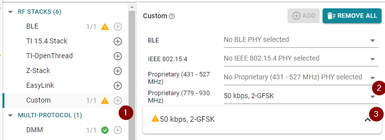
In the settings group, navigate to
PHY Properties→TX Power (dBm)and select some lower TX power.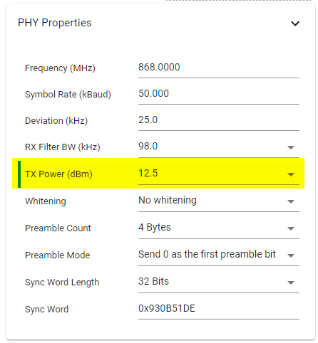
In the settings group, navigate to
Code Export Configuration→Symbol Name Generation Methodand selectCustom.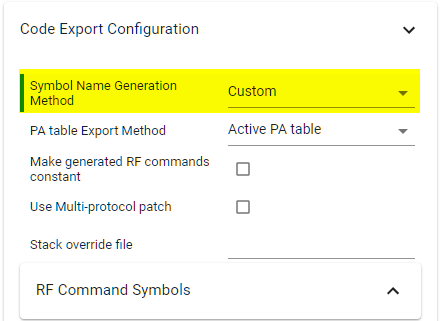
Lastly, we need to add the red LED GPIO in SysConfig. Navigate to the GPIO component and add another GPIO. Rename it to
CONFIG_GPIO_RLEDand connect it to theLaunchPad LED Redhardware.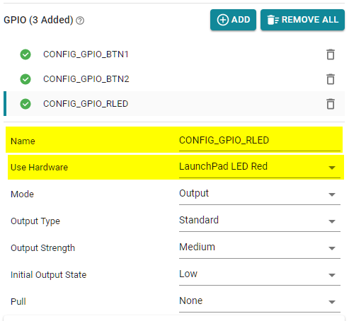
DMM changes
Currently, the Collector application uses the RF driver and is not
initially prepared for DMM. To add flexibility to the project, one can make
the driver inclusion case dependent on which defines are in the current
project. This way, the code will compile both by itself and in a DMM
application. Create an #ifdef USE_DMM where the RF driver header
ti/drivers/rf/RF.h is replaced with the DMM RF map dmm_rfmap.h header.
/* Drivers */
#include <ti/drivers/GPIO.h>
#include <ti/display/Display.h>
#include <ti/drivers/utils/List.h>

// =========== MODIFY START ===========
#ifdef USE_DMM
#include "dmm/dmm_rfmap.h"
#else
#include <ti/drivers/rf/RF.h>
#endif
// =========== MODIFY START ===========
rfCollector.c – replace the RF driver header file
Also include the dmm_scheduler.h and dmm_policy_blesp_rfColl.h headers
files.
/* DMM */
#include "dmm/dmm_scheduler.h"
#include "ti_dmm_application_policy.h"
rfCollector.c – adding DMM header files.
Update Collector Application States
The Collector application states used above serve no purpose unless they are
also utilized somewhere in the collector application. It is now time to have a
look at the Collector radioThread() to identify when it is reasonable to
update the DMM application state.
Would I need to look at the processing thread as well?
No! Simply put, the DMM application states should cover radio related
application states. In the case of the processingThread(), it does not
perform any radio related tasks and hence does not need to update
application states.
One possible start could be to update the states in the beginning of each function using the radio so that the relevant state is set. In between application states, the idle state could be used to mark that the collector currently do not use the radio.
For the collector application, however, this is not enough as some of the states span over several functions. As the radio thread in the RF collector application has a linear execution, a simpler way to implement the state change is to do this inside the main application loop. The following snippet shows an example of how the state transitions could look like for the collector application.
/*
 *  ======== radioThread ========
 */
void radioThread(uintptr_t arg0, uintptr_t arg1)
{
    DMMPolicy_updateStackState(DMMPolicy_StackRole_reserved1, DMMPOLICY_PROP_IDLE);

    ...

    while (1)
    {
        /* Set beacon application state */
        DMMPolicy_updateStackState(DMMPolicy_StackRole_reserved1, DMMPOLICY_PROP_BEACON);
        /* Send a beacon to probe for new nodes */
        nodeAddress = sendBeacon(nextBeaconTime);

        /* If a node request to join, process it */
        if (nodeAddress > 0)
        {
            /* Processing a join request-state */
            DMMPolicy_updateStackState(DMMPolicy_StackRole_reserved1, DMMPOLICY_PROP_JOIN_REQ);

            BeaconStatus_t retVal = processJoinRequest(nodeAddress, nextBeaconTime);

            ...

        }

        /* If there is any joined nodes, process them */
        if (nodeEntries)
        {
            /* Process each node */
            NodeElement_t* node;
            for (node = (NodeElement_t *) List_head(&nodeList);
                 node != NULL;
                 node = (NodeElement_t *) List_next((List_Elem *) node))
            {
                if (!(node->isOrphan))
                {
                    /* Entering "listen for node"-state */
                    DMMPolicy_updateStackState(DMMPolicy_StackRole_reserved1, DMMPOLICY_PROP_LISTENFORNODE);

                    SensorStatus_t retVal = listenForNode(node);
                    ...

                }
                else
                {
                    /* Idle when not listening for a node */
                    DMMPolicy_updateStackState(DMMPolicy_StackRole_reserved1, DMMPOLICY_PROP_IDLE);
                }
            }
        }

        /* Calculate the next beacon time stamp */
        nextBeaconTime = nextBeaconTime + RF_convertMsToRatTicks(BEACON_INTERVAL);
    }
}
rfCollector.c - Add DMM state transitions
This particular use-case could be further simplified by simply setting the initial state to a high-priority one and leave it at that as all states is setup in the same way. To further highlight the DMM functionality in this lab, multiple state transitions are performed which could be redundant.
Extend the DMM Policy
Now that we have added the collector application to the project, we can now exten the DMM policy table with addition policy entries if needed.
In this lab, the desired policy should consider the collector application to always have high priority. However, when forming a BLE connection there is a lot of critical initial communication that should not be disrupted. Because of this, the BLE-stack could be given an increased priority while forming the connection, returning back to lower priority when connected.
However, the current setup with the global priority table ensures that the Proprietary Collector has higher priority than BLE in the normal use case, and BLE has higher priority when establishing a connection. Hence, we don't need to extend the DMM policy table.
Final Changes, Resolve Display Conflicts
Now the integration is almost done but before the project is ready to be tested
some resource conflicts need to be addressed. As both the
simple_peripheral and rfCollector example utilize the Display
driver to output information over the serial port there would be a resource
conflict in the current implementation where both tries to allocate the same
hardware.
To simplify the lab, we will simply comment out the part of rfCollector.c
which opens the handle to the Display driver. In rfCollector.c, comment out
the following code:
void processingThread(uintptr_t arg0, uintptr_t arg1)
{
    Display_Handle displayHandle = NULL;

    // =========== COMMENT OUT START ===========
    /* Open the display handle */
    //displayHandle = Display_open(Display_Type_ANY, NULL);
    // =========== COMMENT OUT END ===========
}
rfCollector.c – comment out Display_open()
Build and download the project to the DMM device. If you did everything correct, you should now have a fully operational DMM device with a BLE simple peripheral and a proprietary RF Collector.
Testing the Final Project
To test this dual project and see that it is actually working we need to
start the RF Sensor again. Open up the two serial terminals by opening the
two LaunchPad serial ports COM*: XDS110 Class Application/User UART and
COM*: XDS110 Class Auxiliary Data Port. While the DMM device is running,
you should be able to verify that the sensor and collector are able to
establish and maintain a connection, just like before we added DMM.
Now, using the BLE central of your choice, you should be able to find the device advertising what you have named it. Connect to it and confirm that you can read out information using the BLE connection while the Collector and Sensor interact simultaneously.
The functionality can be verified by setting up a RF Sensor and simultaneously connect to the DMM device with a smartphone (or your preferred BLE central).
Task 3 – Debug DMM Performance Issues
If something is not functioning properly or if you are seeing unexpected radio performance issues there is most likely a scheduling collision between the two radio protocols. One powerful tool for debugging the radio functionality is to route the RF core PA/LNA signals to GPIO pins so that they can be observed. These signals are toggled as the radio goes in and out of transmission/receiver mode. Observing these signals together with the antenna switching signal can help debugging as it shows when the radio switching between the two protocols and when the radio is active.
Note
While being able to use the antenna switching signal to determine which radio protocol is active when combining 2.4 GHz and Sub-1 Ghz protocols, this is not possible when using the DMM to combine two protocols sharing the same RF path.
It is however still possible to observe the PA and LNA signals to trace radio activity.
The chapter "Routing doorbell signals to GPIO pins" in the Proprietary RF User's Guide goes over how to route the RF core signals to GPIO pins to makes them available for observation.
In this lab, you can do the routing in the rfCollector.c file by doing the
following modifications.
/***** Includes *****/
#include <ti/drivers/pin/PINCC26XX.h>
...

/***** Variable declarations *****/
static PIN_Handle pinHandle;
static PIN_State pinState;

/* PIN configuration */
PIN_Config heartbeatLedPinTable[] = {
    CC1352R1_LAUNCHXL_PIN_RLED | PIN_GPIO_OUTPUT_EN | PIN_GPIO_LOW | PIN_PUSHPULL | PIN_DRVSTR_MAX,

    // =========== EDIT START ===========

    /* Add two additional  pins to the pin configuration table. This makes
       sure the pins we use for the LNA/PA signals is not used any other
       part of the application */

    CC1352R1_LAUNCHXL_DIO21 | PIN_GPIO_OUTPUT_EN | PIN_GPIO_LOW | PIN_PUSHPULL | PIN_DRVSTR_MAX,
    CC1352R1_LAUNCHXL_DIO22 | PIN_GPIO_OUTPUT_EN | PIN_GPIO_LOW | PIN_PUSHPULL | PIN_DRVSTR_MAX,

    // ============ EDIT END ============
 PIN_TERMINATE
};

...

/*
 *  ======== processingThread ========
 */
void *processingThread(void *arg0) {
    Display_Handle  displayHandle;
    PIN_Handle heartbeatLedPinHandle;
    PIN_State heartbeatLedPinState;

    /* Open the PIN handle */
    heartbeatLedPinHandle = PIN_open(&heartbeatLedPinState, heartbeatLedPinTable);
    if (NULL == heartbeatLedPinHandle) {
        /* Error opening the PIN driver */
        while(1) {};
    }

    // =========== EDIT START ===========
    // Map RFC_GPO0 to IO 21
    PINCC26XX_setMux(heartbeatLedPinHandle, CC1352R1_LAUNCHXL_DIO21, PINCC26XX_MUX_RFC_GPO0);
    // Map RFC_GPO0 to IO 22
    PINCC26XX_setMux(heartbeatLedPinHandle, CC1352R1_LAUNCHXL_DIO22, PINCC26XX_MUX_RFC_GPO1);
    // ============ EDIT END ============
rfCollector.c - Routing RF Core PA and LNA signals
Assuming these modifications are done, the following signals should be available for debugging:
- Radio PA Enable (TX) on DIO22
- Radio LNA Enable (RX) on DIO21
- Antenna switch direction on DIO30
The antenna switch direction pin will be LOW when the 2.4 GHz path is
selected and HIGH when the Sub-1 GHz path is selected.
A showcase along with a brief description of what can be seen using these from these signals can be seen below. Pay attention to the scale in each picture since it is not constant.
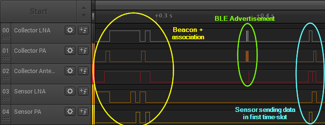
The first image shows the radio activity during a full beacon interval when connected to one Sensor while also sending BLE advertisements. The first thing you see in this image, marked by yellow, is a beacon follow by a join request from the sensor. Marked with green is the typical activity seen when performing BLE advertisements on channel 37-39. Since the device is advertising scannable, the device goes into RX immdediately after sending each advertisement packet in order to listen for scan requests.
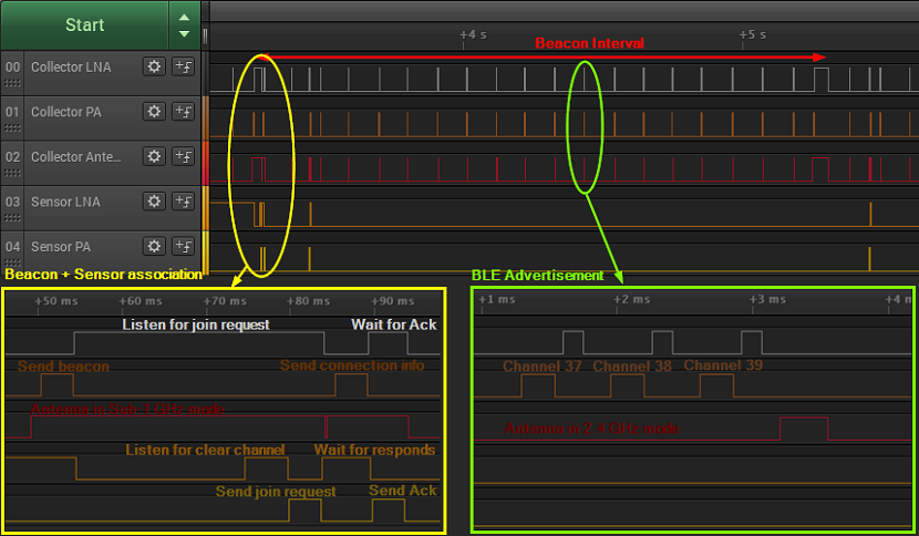
A closer look around the beacon and join request, we can also find the first packet sent by the sensor following the join procedure. This is marked with a cyan color in the picture and is can be easily identified by looking at the antenna switch signal and that the collector starts with an RX rather then a TX as in the beacon case.
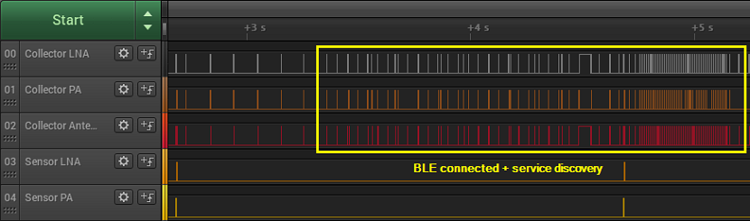
The following image shows the radio activity of the DMM device when a BLE central connects to the DMM device. In contrast to the first image, here there is a lot of data being both transmitted and received during a smaller interval. If this gets disrupted, there is a high chance for the BLE connection to fail.
While all the images above shows a well-functioning DMM use case, the information we could extract from the logic traces can prove helpful when this is not the case.
Limitations
The current limitations are documented in the DMM User's Guide.
This work is licensed under a Creative Commons Attribution-NonCommercial-NoDerivatives 4.0 International License.