Zephyr Project Board Porting Guide#
Texas Instruments™
2 hours read
Introduction#
Welcome to this lab, which will teach you how to add Zephyr support to a custom board. Make sure to pay attention to all of the required hardware and software and to follow the steps carefully to complete your setup.
We’ve seen in a previous SimpleLink Academy training how to build and flash
the Blinky project onto our board. When building the Blinky project, we
used the command
west build -p always -b {BOARD_IDENTIFIER} samples/basic/blinky. The two
most important parts of this command are the path to the sample to build, and
the board identifier. This board identifier indicates to Zephyr which board
configuration should be used to building the firmware.
The list of all supported boards from all supported silicon makers can be
found by running west boards. But one may notice that for Texas
Instruments™, only LaunchPads are supported by Zephyr. If we want to
use Zephyr running on a SimpleLink MCU on a custom board, we need to create
our own custom board configuration.
The goal of this lab is to help you create your own board configuration based on the board configuration for Texas Instruments’s LaunchPads. We will first explain how Zephyr builds firmwares in order to understand what is the role of the board configuration, its link with the MCU configuration and with the drivers. Then we will see how a board configuration is structured using devicetrees to describe the hardware specificities of the board. Finally, we will create a new board configuration for a custom board, and blink the LED of this custom board.
Prerequisites#
For this lab, a host computer running Linux is needed, preferably Ubuntu as this is what this lab will use.
You should already have setup the Zephyr development environment for SimpleLink boards. If this is not already done, you can follow the SimpleLink Academy training about setting up the Zephyr environment.
In order to flash a firmware onto the board, two options are possible :
XDS110 LaunchPad™ development kit debugger, which should include a USB-C to USB-A cable for connecting the XDS110 to a computer.
J-Link Debug Probe, from SEGGER. The J-Link Plus debug probe was used for development and testing, but other J-Link debug probes might work too.
Warning
Older versions of J-Link debug probes hardware are not supported because they do not support dormant mode handling. While version 12.0 is known to be working, version 10.1 is known to be not supported.
You will need a development board which is supported by Zephyr. Here is the list of all boards officially supported by Texas Instruments™ :
Warning
Other Texas Instruments™ boards are supported in Zephyr, but are
maintained by the Zephyr community instead of Texas Instruments™. While
we recommend using one of the boards mentioned above, you could also use one
of these boards, but your mileage may vary :
Understanding how Zephyr builds software#
The Device model#
One of the most important selling point of Zephyr is that it is silicon vendor independent. The way Zephyr code manages to be independent from the hardware running it is by having a common API for all boards. Let’s use the example of the Blinky sample.
/*
 * Copyright (c) 2016 Intel Corporation
 *
 * SPDX-License-Identifier: Apache-2.0
 */

#include <stdio.h>
#include <zephyr/kernel.h>
#include <zephyr/drivers/gpio.h>

/* 1000 msec = 1 sec */
#define SLEEP_TIME_MS   1000

/* The devicetree node identifier for the "led0" alias. */
#define LED0_NODE DT_ALIAS(led0)

/*
 * A build error on this line means your board is unsupported.
 * See the sample documentation for information on how to fix this.
 */
static const struct gpio_dt_spec led = GPIO_DT_SPEC_GET(LED0_NODE, gpios);

int main(void)
{
	int ret;

	if (!gpio_is_ready_dt(&led)) {
		return 0;
	}

	ret = gpio_pin_configure_dt(&led, GPIO_OUTPUT_ACTIVE);
	if (ret < 0) {
		return 0;
	}

  ...

  ret = gpio_pin_toggle_dt(&led);

  ...
}
In this code, we are calling the gpio_pin_toggle_dt(&led) function to toggle
the GPIO value for the led. This function then calls a GPIO driver, which will
write in the correct register to toggle the GPIO. However, toggling a GPIO on
a Texas Instruments™ MCU is a different process from toggling a GPIO on
a MCU from another silicon vendor. This means that we need to have different
drivers for each manufacturer.
The way Zephyr manages to conciliate all silicon vendors is by using Devices. A Zephyr device can be roughly simplified as the following :
Configuration information
A driver implementation for a specific subsystem.
Note
In reality a device is much more than those two elements. A device also has a name field and a state field. They also contain optional fields like dependencies to other devices, power management resources or metadata. Since these fields are not essential for this training, we will ignore them, but it’s good to be aware that Zephyr devices are much more powerful than driver implementations and configuration information.
The subsystem can be something like GPIO, SPI, UART, sensors, and more. Zephyr will use devices to know the specificities of vendor-specific hardware, allowing it to know the correct configuration information and the correct driver for each subsystem should be used at build time.
For example, let’s take a GPIO device for the CC2340R53 LaunchPad, like a LED. This device has a driver implementation for all functions of the GPIO driver API. This device also has configuration information, such as :
The GPIO register
The number of total GPIOs
The DIO line of the GPIO
The initial value for the GPIO
Etc …
If we go back to the example of the Blinky sample, the led variable used in
the instruction gpio_pin_toggle_dt(&led) is the specification of a device.
This allows the gpio_pin_toggle_dt to know which driver implementation
should be called, and with which parameters.
static inline int gpio_pin_toggle_dt(const struct gpio_dt_spec *spec)
{
	return gpio_pin_toggle(spec->port, spec->pin);
}

static inline int gpio_pin_toggle(const struct device *port, gpio_pin_t pin)
{
	[...]
	return gpio_port_toggle_bits(port, (gpio_port_pins_t)BIT(pin));
}

static inline int gpio_port_toggle_bits(const struct device * port, gpio_port_pins_t pins)
{
	[...]
	return z_impl_gpio_port_toggle_bits(port, pins);
}

static inline int z_impl_gpio_port_toggle_bits(const struct device *port,
					       gpio_port_pins_t pins)
{
	const struct gpio_driver_api *api =
		(const struct gpio_driver_api *)port->api;

	return api->port_toggle_bits(port, pins);
}
As you can see from the functions called by gpio_pin_toggle_dt, they
culminate in a function called z_impl_gpio_port_toggle_bits. This function
then uses the driver API for our LED device, and calls a function from this
API, with the configuration information as the parameters for this function
call. The driver function called is a function specific to the device, which
is therefore specific to the silicon vendor given in the build parameters.
We now understand that Zephyr uses devices to tell the firmware which driver functions to use and what data to give them. This means that the only thing we have to do to add Zephyr support to our custom board is to create a list of devices that are specific to our board, and which can be used by developers when calling the Zephyr subsystem APIs. This list of devices in Zephyr are known as Devicetrees.
Zephyr devicetrees#
A Zephyr devicetree is a hierarchical data structure that describes the hardware we are using. The two most important hardware that we will describe are the SoC and the board. Devicetrees are written in a devicetree grammar which is very similar to the devicetree grammar from Linux. These devicetrees will then be transformed into C header files that can be included and used inside a Zephyr project.
Here is an example of a very minimal devicetree :
/dts-v1/;

/ {
	sysclk: system-clock {
		compatible = "fixed-clock";
		clock-frequency = <48000000>;
		#clock-cells = <0>;
	};
};
Since devicetrees are hierarchical data structures, a devicetree defines nodes, which can be the children of another node. You can see all the nodes in the devicetree as different devices. In this example, we describe two nodes :
The root node
/The node named
system-clock, which is the child of the root node
As we said previously, we will abstract a device to be only configuration
information and a driver implementation. In Zephyr devicetrees, the driver
implementation is defined by the compatible field of the node. From the
driver’s point of view, the driver implementation defines a DT_DRV_COMPAT
macro with a unique string, and all devicetree nodes with their compatible
field being equal to this DT_DRV_COMPAT will be associated with this device.
This string usually is the brand of the silicon vendor and the name of the
driver. For example, here is how the Bluetooth device on the CC2340R53
LaunchPad board gets associated to the right Bluetooth HCI driver.
DT_DRV_COMPAT macro definition in the TI Bluetooth HCI driver.#[...]
#define DT_DRV_COMPAT ti_bt_hci
[...]
[...]

/ {
  [...]

	ti_bt_hci: ti_bt_hci {
		compatible = "ti,bt-hci";
		status = "okay";
	};
};

[...]
In this example, the value of the compatible field is ti,bt-hci, and it is
successfully matched against the DT_DRV_COMPAT value of the TI Bluetooth HCI
driver. The build toolchain of Zephyr will therefore build the hci_ti.c file
and use it as the Bluetooth HCI driver for the CC2340R53 LaunchPad board.
Note
In the example, the compatible field string is a little bit different than
the DT_DRV_COMPAT values. This is because the DT_DRV_COMPAT value should
not have any special characters, and so all special characters from the
compatible field are replaced by underscores.
Now that we know how the drivers are associated with devices, we can see how the devices are associated with configuration data. Using the previous example of a very minimal devicetree :
/dts-v1/;

/ {
	sysclk: system-clock {
		compatible = "fixed-clock";
		clock-frequency = <48000000>;
		#clock-cells = <0>;
	};
};
In this example, clock-frequency and #clock-cells are fields that can be
used in the driver as configuration data. But this data on its own is useless,
it needs additional information to be correctly interpreted. How can the
driver know the type of the #clock-cells field ? Is it a float, a double or
an integer ? Is it signed or not ? The solution to this problem is Zephyr
devicetree binding.
Zephyr devicetree bindings#
Zephyr devicetree bindings are files that describe rules for the configuration
data needed for the drivers of a device. These usually include properties like
their type, or a human-readable description, but can be more specific. For
example, here is the Device bindings file for the fixed-clock driver :
fixed-clock driver## Copyright (c) 2019 Derek Hageman <hageman@inthat.cloud>
# SPDX-License-Identifier: Apache-2.0
description: Generic fixed-rate clock provider
compatible: "fixed-clock"
include: clock-controller.yaml
properties:
clock-frequency:
type: int
description: output clock frequency (Hz)
required: true
"#clock-cells":
const: 0
In this example of the device bindings for the fixed-clock driver, we find
the two properties that were defined in the device tree that used this driver.
The property clock-frequency has a type int, a description, and is
required to use the driver.
This is useful for two reasons :
The bindings create rules that the devicetrees have to follow, and leaves no room for interpretation of what the devicetree actually describes. Thanks to the rules created by the bindings, the syntax and properties of the devicetrees can be verified at compile time instead of causing an error at runtime.
The rules and the properties extracted from the bindings allow the devicetrees to be transformed into useful C code, that can be used by driver functions in Zephyr.
The second point is the most important. The way that Zephyr creates C code
that can change from a silicon maker to another is by converting the
devicetree of the board into a large C header file called
devicetree-generated.h. You can find this file after a successful build under
zephyrproject/zephyr/build/zephyr/include/generated/zephyr/devicetree_generated.h.
The Zephyr devicetree documentation
provides a good visual representation of how this header file is generated.
You can ignore the devicetree overlays, as they are project-specific.

Schema of how the Zephyr devicetree-generated.h file is generated.#
The devicetree-generated.h file contains a lot of C macros with a specific
format. These macros are then used by the Zephyr driver functions and macros
in order to use the properties that were defined in the devicetree. Here is an
example of what such a devicetree-generated.h would look like for the
system-clock node of our previous example devicetree.
/*
 * Devicetree node: /system-clock
 *
 * Node identifier: DT_N_S_system_clock
 *
 * Binding (compatible = fixed-clock):
 *   $ZEPHYR_BASE/dts/bindings/clock/fixed-clock.yaml
 *
 * (Descriptions have moved to the Devicetree Bindings Index
 * in the documentation.)
 */

/* Node's full path: */
#define DT_N_S_system_clock_PATH "/system-clock"

/* Node's name with unit-address: */
#define DT_N_S_system_clock_FULL_NAME "system-clock"

/* Node parent (/) identifier: */
#define DT_N_S_system_clock_PARENT DT_N

/* Node's index in its parent's list of children: */
#define DT_N_S_system_clock_CHILD_IDX 0

[...]

/* Generic property macros: */
#define DT_N_S_system_clock_P_clock_frequency 48000000
#define DT_N_S_system_clock_P_clock_frequency_EXISTS 1
In this example of the devicetree-generated.h, we can find the clock
frequency property that we defined in our devicetree. It’s now usable from the
C code by including the <devicetree.h> header in our driver implementation
or in other places to extract this property. Since this header file is
generated for each project and each board, this allows Zephyr to be completely
silicon-vendor independent, because as long as every silicon vendor adds the
clock-frequency to the system-clock device in their devicetree, they can
build any project that uses a system clock.
Adding Zephyr support to a new board#
Now that we understand how Zephyr builds firmware from devicetrees, we will add Zephyr support for a new board. For this we will start from the board files for the CC2340R53 LaunchPad board, and we will transform the devicetree and board files to add Zephyr support to a custom board. The custom board used will be a Bluetooth Low Energy (BLE) mouse using a CC2340R53 MCU.
Task 1 : Creating a copy of the CC2340R53 LaunchPad board#
First of all, we will copy the CC2340R53 LauchPad board files. The files for
this board are located under zephyrproject/zephyr/boards/ti/lp_em_cc2340r53.
Lets copy this folder, paste it in the ti folder, and rename it
cc2340r53_mouse.
Error
In this training, we will use the CC2340R53 LaunchPad as the source board files, because our board will use the CC2340R53. If your board uses a different MCU, it’s better to copy the board files from the LaunchPad of this MCU instead.
Warning
In this training, we will call our board cc2340r53_mouse. But you can replace
cc2340r53_mouse by another string more adapted to your board. Be careful
however to always replace the cc2340r53_mouse string by your board’s name.
Your board name must have no space and must not have any special characters,
except dashes and underscores.
The files in this folder can be split into multiple categories :
Documentation files
Board metadata files
Flash and Debug support files
Kconfig files
Devicetree files
Documentation files#
The documentation files are human-readable information about the board. These
files are located under the cc2340r53_mouse/doc folder. It contains an
index.rst file that acts as documentation for the board, and an img folder
for images for the board. While those files are not necessary to build a
firmware on our custom board, they help other readers to understand what the
board is. If you plan on committing this board to the official Zephyr
repository, those files are mandatory.
Board metadata files#
The board metadata files are files that give extra information about the board,
but unlike the documentation files, those files are usually in YAML format to
be easily read by a build script. The board metadata files include
board.yml and lp_em_cc2340r5.yaml.
board.yaml#
board.yaml defines the board at a high level. This includes the SoC,
board variants, and board revisions. We will change the board identifier but
not the SoC name, since we are using the SoC CC2340R53 for our board.
board.yml board file for the mouse board#board:
name: cc2340r53_mouse
vendor: ti
socs:
- name: cc2340r53
<board_name>.yaml#
lp_em_cc2340r53.yaml is similar to board.yml but goes more in depth and
defines important information such as the ram and flash size, the name and the
identifier of the board. This identifier is the one used by the west build
command to identify which devicetrees to use. For adding Zephyr support to our
board, we will rename the file, and change the identifier and name. If other
values are different for your board, feel free to change them.
identifier: cc2340r53_mouse
name: BLE Mouse Using CC2340R53
type: mcu
arch: arm
ram: 36
flash: 512
toolchain:
  - zephyr
  - gnuarmemb
  - xtools
supported:
  - gpio
vendor: ti
Flash and Debug support files#
The only file that adds support for Flash and debug is the board.cmake file.
This gives build information to Zephyr to add support for flashing and
debugging. For example the board.cmake file for the CC2340R53 LaunchPad gives
the additional --device=CC2340R53 flag to J-Link. Unless you are sure you
know what you are doing, you should not modify this file.
Kconfig files#
Kconfig is a way to select configuration settings at build time. Configuration options (often called symbols) are defined in Kconfig files, which also specify dependencies between symbols that determine what configurations are valid. Symbols can be grouped into menus and sub-menus to keep the interactive configuration interfaces organized. The goal is to support configuration without having to change any source code.
Note
The Kconfig configuration system is used by Zephyr but is also present in the Linux kernel.
When building the firmware, Zephyr will aggregate the configuration settings
from the different Kconfig files, into one large header file. This header file
is called autoconf.h, and can be found under
zephyrproject/zephyr/build/zephyr/include/generated/zephyr/autoconf.h.
The Kconfig files used to generate this file are present at different levels :
SoC level
Board level
Project level (
prj.conffile of a project)
The Kconfig files at the board level are Kconfig, Kconfig.defconfig,
Kconfig.<board_name> (Kconfig.lp_em_cc2340r53 in our case) and
<board_name>_defconfig (lp_em_cc2340r53_defconfig in our case).
Kconfig.<board_name>#
The Kconfig.lp_em_cc2340r53 file is a Kconfig file to select the SoC of the
board and other SoC settings. We need to rename the file to the right name,
Kconfig.cc2340r53_mouse. We also need to change the content of the file since
the Kconfig board name symbol has changed. Here is the new content of the
Kconfig.cc2340r53_mouse file :
# Copyright (c) 2024 Texas Instruments Incorporated
# Copyright (c) 2024 BayLibre, SAS
#
# SPDX-License-Identifier: Apache-2.0

config BOARD_CC2340R53_MOUSE
	select SOC_CC2340R53

config BOARD_USE_LF_XOSC
	bool "Use external low-frequency crystal"
	default y
Kconfig.defconfig#
The Kconfig.defconfig file is the default configuration values for our board.
This selects Kconfig symbols that are mandatory for our board and SoC.
These Kconfig values cannot be changed by a user in the project level Kconfig
files. For example, the Kconfig.defconfig for the CC2340R53 LaunchPad sets
the Bluetooth heap size with BT_LL_HEAP_SIZE. Changing those values might
cause problems with the bluetooth stack, so a sane default is set in this
Kconfig board file. The only value that is safe to change is the
BT_COMPANY_ID value, because it sets the Bluetooth Company ID to the Texas
Instruments™ ID. We need to change the content of the file since
the Kconfig board name symbol has changed. Here is the new content of the
Kconfig.defconfig file :
# Copyright (c) 2024 Texas Instruments Incorporated
#
# SPDX-License-Identifier: Apache-2.0

rsource "../lpf3_common/Kconfig.defconfig"

if BOARD_CC2340R53_MOUSE

if BT

config ZEPHYR
  bool
  default y

config BT_LL_HEAP_SIZE
  hex
  default 0x1880

config BT_BUF_EVT_RX_SIZE
  default 255

config BT_BUF_ACL_RX_SIZE
  default 255

config BT_BUF_ACL_TX_SIZE
  default 251

config BT_BUF_CMD_TX_SIZE
  default 255

config BT_COMPANY_ID
  default 0x000D

choice BT_RECV_CONTEXT
  bool
  default BT_RECV_WORKQ_BT if BT_MESH
  default BT_RECV_WORKQ_SYS
endchoice

endif # BT

endif # BOARD_CC2340R53_MOUSE
<board_name>_defconfig#
The <board_name>_defconfig Kconfig file is very similar to the
Kconfig.defconfig, except the selected Kconfig symbols can be changed by a
user in the project level Kconfig files. They are not mandatory values, but
suggested default values. For example, the line CONFIG_PM=y enables the
Power Manager in every project that use the board. While most project would
benefit from this, the user can choose to disable it, this is not a mandatory
configuration option. We will not change the content of this file. We will
only rename the file to cc2340r53_mouse_defconfig.
Kconfig#
The Kconfig file can add Kconfig settings which are specific to the current
board. For the CC2340R53 LaunchPad board, these settings are common to every
cc23xx MCU, so you should always at least keep the
rsource "../lpf3_common/Kconfig" line to include those common settings. In
this guide we will not change this file.
Devicetree files#
The devicetree files are used to create the final devicetree for the board. We will change these files a lot because they are the one that describe what devices are there on the board.
They are divided into two files extensions : .dtsi and .dts files.
The .dtsi files are devicetree files that are only meant to be included
inside .dts files. The three devicetree files in the board folder are
boosterpack_connector.dtsi, lp_em_cc2340r53-pinctrl.dtsi and
lp_em_cc2340r53.dts.
boosterpack_connector.dtsi#
The boosterpack_connector.dtsi file describes the mapping between the pin
connectors and the DIO lines. For example, pin 9 of the connector is mapped to
DIO24 on the board.
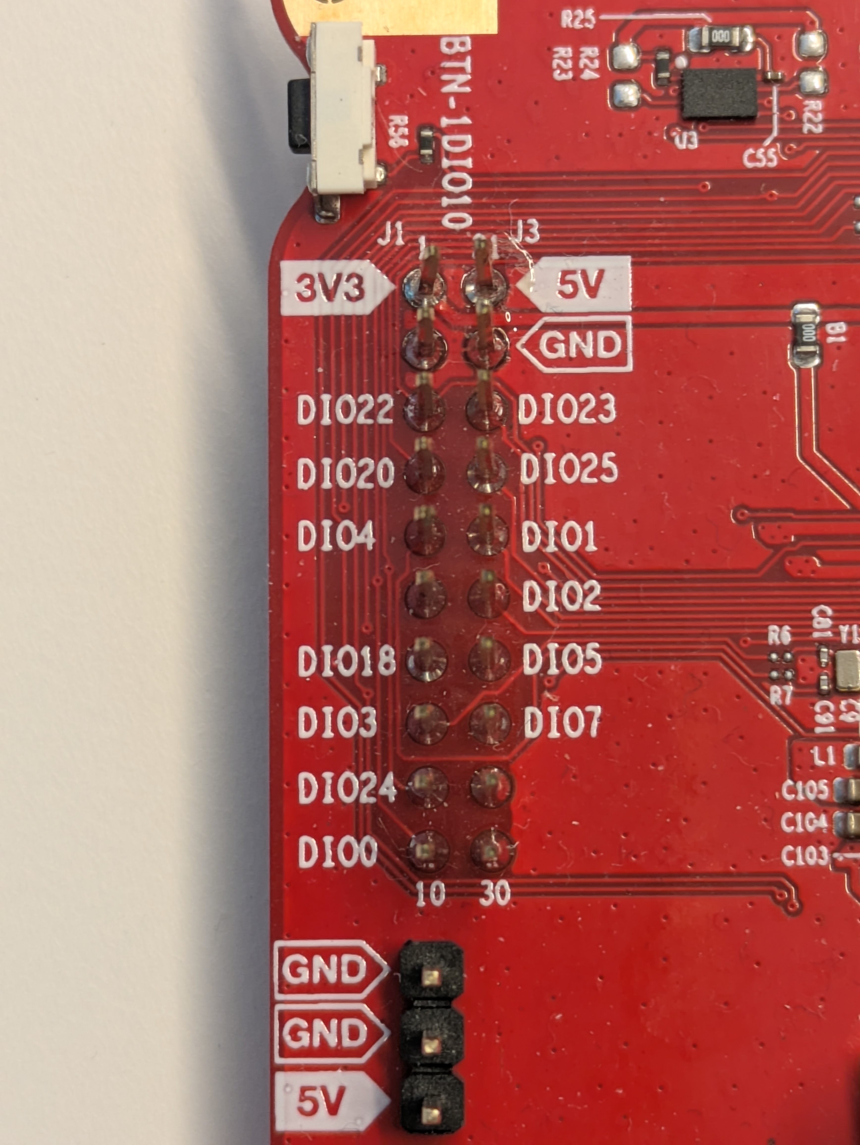
The boosterpack connector of the CC2340R53 LaunchPad.#
Since your custom board is not a boosterpack, you can safely remove this file in your custom board folder.
lp_em_cc2340r53-pinctrl.dtsi#
The lp_em_cc2340r53-pinctrl.dtsi file describes the pinmux mapping for the
drivers. Instead of having the pinmux values spread all around the devicetree,
we made the choice to put everything in one file. The configuration values for
the pinmux are stored inside devices, which can later be referenced by their
name in the final devicetree file. Unlike the other files, the name of the
file is not very important, but we still rename this file to
cc2340r53_mouse-pinctrl.dtsi for coherence with the other files naming
convention.
lp_em_cc2340r53.dts#
The lp_em_cc2340r53.dts is the main devicetree file. It starts with
include macros to include the dtsi files from the folder, but also the dtsi
files for the CC2340R53 MCU. This allows this devicetree file to only focus
on the specifics of the board, and to put all the MCU-specific values in common
for all boards that need them. We need to rename the file to
cc2340r53_mouse.dts. Since we deleted the boosterpack_connector.dtsi file
and renamed the lp_em_cc2340r53-pinctrl.dtsi, we also need to change the
content of this file. Here’s the changed includes for this file :
/*
 * Copyright (c) 2024 Texas Instruments Incorporated
 * Copyright (c) 2024 BayLibre, SAS
 *
 * SPDX-License-Identifier: Apache-2.0
 */

/dts-v1/;

#include <ti/cc2340r53.dtsi>
#include "cc2340r53_mouse-pinctrl.dtsi"
#include <zephyr/dt-bindings/gpio/gpio.h>
#include <zephyr/dt-bindings/pwm/pwm.h>
#include <zephyr/dt-bindings/input/input-event-codes.h>

[...]
Testing the changes#
After all those changes our board folder should look like this :
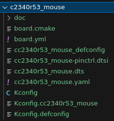
Final files in the new board folder.#
We should now be able to see our board by running west boards. We can filter
for our board by running west boards | grep mouse. If this command returns
the name of our board, it is successfully detected !
We can try then to build a sample for our new board, and run it on a CC2340R53
LaunchPad. To try this, we can move to the zephyr folder, run
west build -p always -b cc2340r53_mouse samples/basic/blinky, and flash the
resulting firmware. If we can see the led blinking, then we have successfully
created a new board in Zephyr. For now, this board almost exactly the same
board as the CC2340R53 LaunchPad, but we will change this in the next task.
Task 2 : Changing the devicetree to fit our custom schematics#
Now that we have a new working board folder, we can start changing the
devicetree of this board to adapt it for our board. In this task we will
show the example of changing the DIO line of the led0 device, so that the
blinky sample will work on our custom board.
For this, we first need to take a look at the hardware schematics of our board.
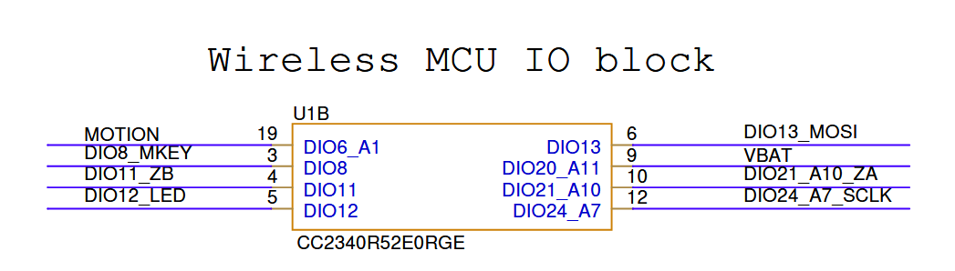
The schematics of the IO block for the CC2340R53 with RGE packaging for the BLE mouse board#

The schematics of the LED for the BLE mouse board#
The LED of our mouse board is activated using GPIO with the DIO 12. If we look
at the devicetree in cc2340r53_mouse.dts we currently have for the mouse, we
can see the following led devices :
/ {
	model = "LP_EM_CC2340R53";
	compatible = "ti,lp_em_cc2340r53";

	[...]

	aliases {
		led0 = &led0;
		led1 = &led1;
		led0 = &led0;
		sw0 = &btn0;
		sw1 = &btn1;
		pwm-led0 = &pwm_green;
		pwm-led1 = &pwm_red;
		watchdog0 = &wdt0;
		mcuboot-led0 = &led1;
		mcuboot-button0 = &btn1;
		[...]
	};

	leds {
		compatible = "gpio-leds";
		led0: led_0 {
			gpios = <&gpio0 15 GPIO_ACTIVE_HIGH>;
			label = "Green LED";
		};
		led1: led_1 {
			gpios = <&gpio0 14 GPIO_ACTIVE_HIGH>;
			label = "Red LED";
		};
	};

  [...]

};

[...]
The CC2340R53 LaunchPad board has two LEDs, one green and one red. The green
LED uses DIO 15, and the red LED uses DIO 14. GPIO_ACTIVE_HIGH is a GPIO
flag, it indicates that the physical level of the LED is high when the logical
level is high. We want to keep this flag for the LED of our mouse board,
because our LED will emit light when the physical level of the wire is high.
The only thing we need to change is to delete the second led, and to change
the DIO used for the LED.
Hint
Zephyr makes a distinction between the physical level and logical level of a pin. The physical level is the physical voltage of the pin (low if 0V, high if 3V), while the logical level is the level the application writes to the pin. Usually the physical level and logical level are the same for a LED, but for a button with a pull-up resistor or a “Chip Select” pin, those devices usually have their logical level be the opposite of the physical level.
We will therefore change the LED device description to the following :
/ {
	model = "CC2340R53_MOUSE";
	compatible = "ti,lp_em_cc2340r53";

	[...]

	aliases {
		led0 = &led0;
		sw0 = &btn0;
		sw1 = &btn1;
		pwm-led0 = &pwm_green;
		pwm-led1 = &pwm_red;
		watchdog0 = &wdt0;
		mcuboot-button0 = &btn1;
		[...]
	};

	leds {
		compatible = "gpio-leds";
		led0: led_0 {
			gpios = <&gpio0 12 GPIO_ACTIVE_HIGH>;
			label = "LED";
		};
	};

  [...]

};

[...]
Warning
“Wait ! We changed the model property of the root node, but not the
compatible property. Why did we not change the compatible property to
something like compatible = "ti,cc2340r53_mouse"; ?”
The reason why we did not change the compatible property is because this
property defines what drivers should be used. We want to use the drivers that
are already made for the CC2340R53 MCU instead of re-creating all the drivers
from the ground up. This is one of the strength of Zephyr, the device model
allows us to change the property of the board but still re-use the drivers for
the SoC.
We can try then to build the blinky sample for our mouse board, and run it the
actual mouse hardware. To try this, we can move to the zephyr folder, run
west build -p always -b cc2340r53_mouse samples/basic/blinky, and flash the
resulting firmware.
Hint
If we can see the led blinking, then congratulations ! We have successfully ported the devicetree of the CC2340R53 LaunchPad to the Mouse board.
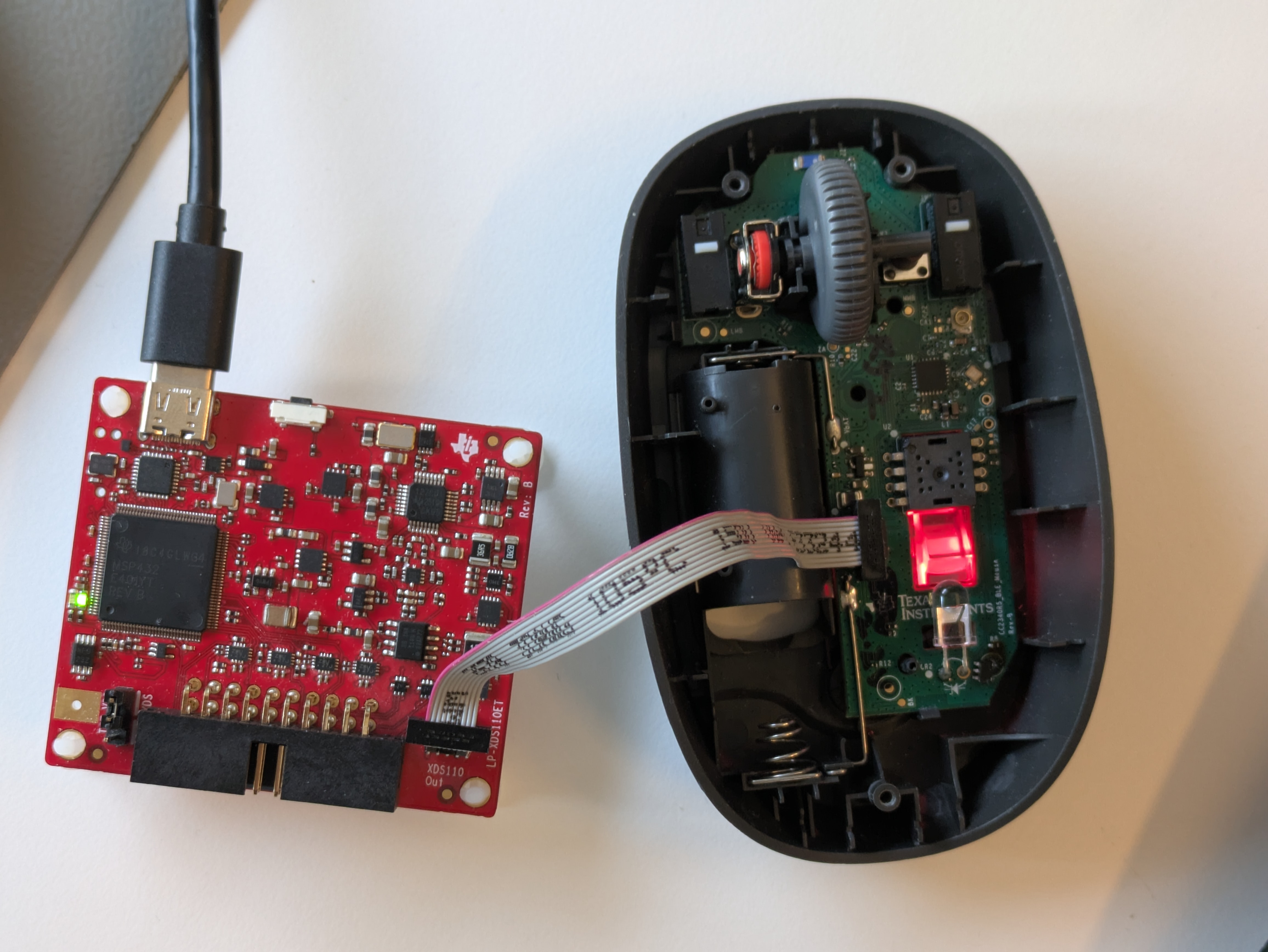
The LED of the mouse board blinking. The mouse board is connected through JTAG to a XDS110#
Resources to go Further#
In this training we have seen how to create a new board folder for Zephyr, what the configuration files for this board are used for, and a practical example of changing the devicetree by changing the DIO line for the LED. However, this is only a hands-on introduction to the subject, and there is still a lot that can be said about them. This section is focused on resources from the official Zephyr documentation and the next steps one can take to learn more about board porting on Zephyr.
The Board Porting Guide gives a complete in-depth guide of porting your board to Zephyr. It explains all possible files in a board folder, the nomenclature between the different layers of the boards, and the good practices for porting a board.
The Devicetree Intro is a conceptual overview of devicetrees and how Zephyr uses them. It explains the syntax, the properties and more.
The Devicetree HOWTOs are a list of devicetree guides for Zephyr. They explain overlays, how to debug devicetrees, the file they generate and their link with device drivers.
The Device Driver Model page explains more in depth what is a driver, how can they be used and how to create your own drivers
The Devicetree Bindings page explains how Zephyr’s build system uses bindings, the syntax and good practice rules for bindings.
The Kconfig page gives more specific explanations to Kconfigs in Zephyr, such as preprocessor functions, interactive graphical interfaces for configuration and best practices for them.
Last but not least, the Kconfig Search Tool which allows to search for specific Kconfig symbols using keyworks or RegEx.