Zephyr Project Environment Setup#
Texas Instruments™
2 hours read
Introduction#
Welcome to this lab, which will teach you how to setup your work environment for Zephyr and how to create your first Zephyr project. Ensure you have all required hardware and software, and follow the steps carefully to complete your setup.
What is Zephyr#
Zephyr Project (usually shortened as Zephyr) is an open source scalable real-time operating system (RTOS) supporting multiple hardware architectures including ARM, RISC-V, X86 and more. The goal for Zephyr is to bring together silicon vendors and development tool vendors under one RTOS in order to make the developer experience easier and more streamlined. Zephyr allows developers to write code for one silicon vendor, and to easily port it for every board supported by Zephyr. Since Zephyr supports more than 750 boards, this diversity gives developers and product manufacturers multiple options to solve their embedded RTOS challenges with Zephyr.
Zephyr is a SDK similar to the SimpleLink SDK created by Texas Instruments™. Both are receiving official support from Texas Instruments™, but the main difference is that Zephyr is open source while the SimpleLink SDK is not. The tools provided by Zephyr to develop software are also different. For example, while Zephyr uses the ´west´ command line tool to build, flash and debug firmware, the SimpleLink SDK uses Code Composer Studio.
Prerequisites#
For this lab, a host computer running Linux is needed, preferably Ubuntu as this is what this lab will use.
In order to flash a firmware onto the board, two options are possible:
XDS110 LaunchPad™ development kit debugger, which includes a USB-C to USB-A cable for connecting the XDS110 to a computer.
J-Link Debug Probe, from SEGGER. The J-Link Plus debug probe was used for development and testing, but other J-Link debug probes might work too.
Warning
Older versions of J-Link debug probes hardware are not supported because they do not support dormant mode handling. While version 12.0 is known to be working, version 10.1 is known to be not supported.
You will need a development board which is supported by Zephyr. Here is the list of all the F3 boards which are officially supported by Texas Instruments™ :
Warning
Texas Instruments™ officially supports the CC2340R5x devices. The CC32xx and CC13xx_CC26xx devices are only supported by the Zephyr community in the upstream repositories, and not by Texas Instruments™. While we recommend using one of the boards mentioned above, you could also use community-supported boards, but Texas Instruments™ cannot offer support for these boards :
Task 1 : Installation of the Zephyr development environment#
In this task, we will setup a Zephyr development environment on Linux, to allow us to build and flash Zephyr projects on a SimpleLink™ board.
Upstream Zephyr and Downstream Zephyr#
The Zephyr Project is an open source project, where everyone ranging from individual developers to silicon makers like Texas Instruments™ can contribute by adding features, fixes, or support for new boards. However, in order for this contribution to work, there needs to be strict guidelines that every contributor must follow. This includes coding guidelines, passing all tests, being peer reviewed and more. Additionally, the features added to Zephyr by a contributor might only be made public in a major version much later after they were done being developed. This adds a significant delay between the time we create features, and the time developers have access to them.
For all those reasons, Texas Instruments™ has decided to split their Zephyr implementation and offering into two Github repositories : an Upstream and a Downstream :
The upstream is the official Zephyr Project Github repository. This repository will contain the features that comply with every contributor requirement, and are fully tested and reviewed. The upside of using the upstream is that the implementation is more stable and has to comply with the Zephyr guidelines. The downside is that it will not contain any beta or any of the latest board or features from Texas Instruments™.
The downstream is a fork of the official Zephyr Project Github repository, owned by Texas Instruments™. Unlike the upstream, This repository will contain the latest TI boards and software features which will go into the upstream. While the features are tested using internal tools, they may not yet pass all of the official Zephyr tests, which makes them beta features.
Note
This method of splitting Zephyr code into an upstream and a downstream is not uncommon, as other silicon makers are doing it too for the same reasons.
Features |
Zephyr Upstream |
Zephyr Downstream |
|---|---|---|
Can build on boards from other silicon makers |
✅ |
✅ |
Can build on TI F3 boards |
⚠️ Not necessarily |
✅ |
Has the latest software board features |
⚠️ Not necessarily |
✅ |
Is using the latest Zephyr version |
✅ |
⚠️ Not necessarily |
Test coverage |
More complete |
Internal tools only |
Quality level on TI F3 boards |
Production |
Beta and Production |
In this lab, the Texas Instruments™ Zephyr downstream will be used, in order to have access to the latest features and to be able to use the more recent boards.
Installing Downstream Zephyr#
In order to install the downstream of Zephyr, we will follow the official Zephyr installation instructions for the version we want to use. While we can find the instructions on how to install the latest version of Zephyr here, our downstream is not using the latest version. At the time of writing this, the downstream is using Zephyr 3.7.0, but this might change in the future. The first step will be therefore to find which Zephyr version is our downstream using.
To find which Zephyr version is our downstream using, we can go to the
Zephyr downstream’s tags section
and check the most recent tag. The tag will have a format similar to the
following : v{UPSTREAM_ZEPHYR_VERSION}-ti-{DOWNSTREAM_TI_VERSION}. For
example, the tag v3.7.0-ti-8.40.00_ea means that the latest version of the
downstream is using the Zephyr SDK version 3.7.0.
Note
The Zephyr downstream version is divided into 3 sections : the major version,
minor version and patch version, separated by dots. This downstream version
refers to the version of F3 Core SDK being used. The version can also have
an optional qualifier such as ea which stands for Early Access. Downstream
versions without this qualifier should be treated as production worthy
releases.
Once we know our Zephyr version, we can go to
Zephyr’s installation documentation, and on the bottom left, click on v: latest,
and select your Zephyr version under Document Release Versions.
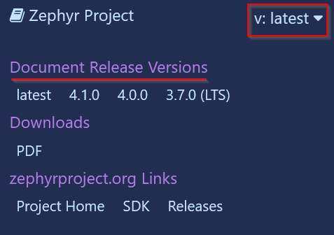
Buttons to select the different versions of Zephyr’s installation guide#
We can now follow the guide until the west init command. When getting
the Zephyr source code with west init, we must tell west to look for the
downstream instead of the upstream. For this we replace the following command :
west init ~/zephyrprojectBy this command :west init -m https://github.com/TexasInstruments/simplelink-zephyr --mr {TAG-NAME} ~/zephyrprojectWe can replace{TAG-NAME}by the tag name for the Zephyr downstream that we chose earlier, for example the tagv3.7.0-ti-8.40.00_ea.
Error
Changing this step in the installation guide is very important. Without this step, Zephyr would use the upstream instead of the downstream, not making use of the latest updates done in the downstream.
This step was the only one we needed to do differently. We can continue following the installation instructions from Zephyr’s documentation.
Task 2 : Building and Flashing the blinky sample#
In this task, we will build and flash the blinky sample on a SimpleLink™ board. Blinky is one of the out-of-the-box samples given by Zephyr in the SDK, so we will not have to write the code ourselves.
Building the blinky sample#
We have now installed the Zephyr downstream, and we can start building and
flashing a project. For this we first need to know for which board we will
build the project. Each board has a unique identifier, and every board
identifier can be listed using the command west boards. If you want to
filter for the Texas Instruments SimpleLink™ boards, you can use the
following command : west boards | grep cc[0-9][0-9].
Warning
If your terminal returns an error similar to Command 'west' not found, this
means that you did not activate your Zephyr venv. To activate it, you need to
run the command source .venv/bin/activate in your zephyrproject folder,
where you created your venv during the installation of Zephyr.
Once we have our board’s unique identifier, we can build the blinky sample
using the following command from the zephyr folder :
west build -p always -b {BOARD_IDENTIFIER} samples/basic/blinky. This will
build the firmware and place the resulting hex files under
build/zephyr/zephyr.hex and build/zephyr/zephyr.elf.
Note
The -p option is a shorthand for the
--pristine option.
This option clears the build folder from any previously generated firmware
before building the new one. This is especially important for switching build
between two boards, as Zephyr may sometimes not correctly detect that some
files need to be re-built for the new board.
Flashing the blinky sample#
To flash the blinky sample onto the LaunchPad, three methods can be used : OpenOCD, UniFlash or West flash.
OpenOCD (shorthand for Open On-Chip Debugger) is an open-source tool used for debugging and programming embedded systems. It is the recommended way to flash firmware using Zephyr, since it does not requires a GUI like UniFlash does, and it doesn’t have the complicated wiring of J-Link. The only thing needed to use OpenOCD is a XDS110 debugger, supplied with TI Launchpads.
Please note that this method is incompatible with blank devices, since OpenOCD requires a valid CCFG to flash the firmware. If you have a blank device, or if the CCFG of your device is corrupted, you need to flash it using UniFlash to restore a valid CCFG.
To use OpenOCD, you need to download the TI release of OpenOCD, because it contains the additional board files for TI’s SimpleLink boards. These files are necessary to flash the boards, because they provide OpenOCD with additional settings, like the adapter speed or the GDB port. The download links for TI’s OpenOCD are the following :
Once you have downloaded the latest OpenOCD release, you can uncompress the archive. In the uncompressed folder, you can hold shift and press right click to open a menu. In this menu, you can select “Open in terminal” to open a terminal and move in the folder.
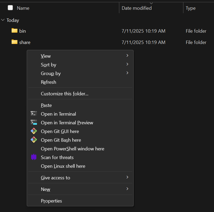
“Open in terminal” button when holding shift and pressing right click#
Once in this terminal, you should be placed inside the OpenOCD folder, like this :
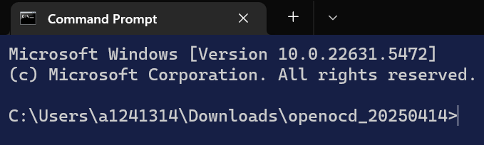
Opened terminal in the OpenOCD folder#
You can then run the following command to start the OpenOCD server :
.\bin\openocd.exe -f .\share\openocd\scripts\board\<board_name>.cfg. You
need to replace <board_name> by the name of your board. You can see all
possible boards in the .\share\openocd\scripts\board\ folder. For example,
the name for the CC2340R53 LaunchPad is ti_lp_em_cc2340r53.
Once the server is open, you can open a second terminal and enter the following
command : telnet localhost 4444. This will connect the terminal to the
OpenOCD server. You can then flash the software by running
program <program_path> reset. You need to replace <program_path> by the
path to the file you want to flash. On Windows, you might need to escape the
backslashes for the path. For example, here is the full command used to flash
the file called zephyr.hex on the desktop :
program C:\\Users\\username\\Desktop\\zephyr.hex reset. Once you run the
command, your terminal should flash the firmware. Here is a typical output :
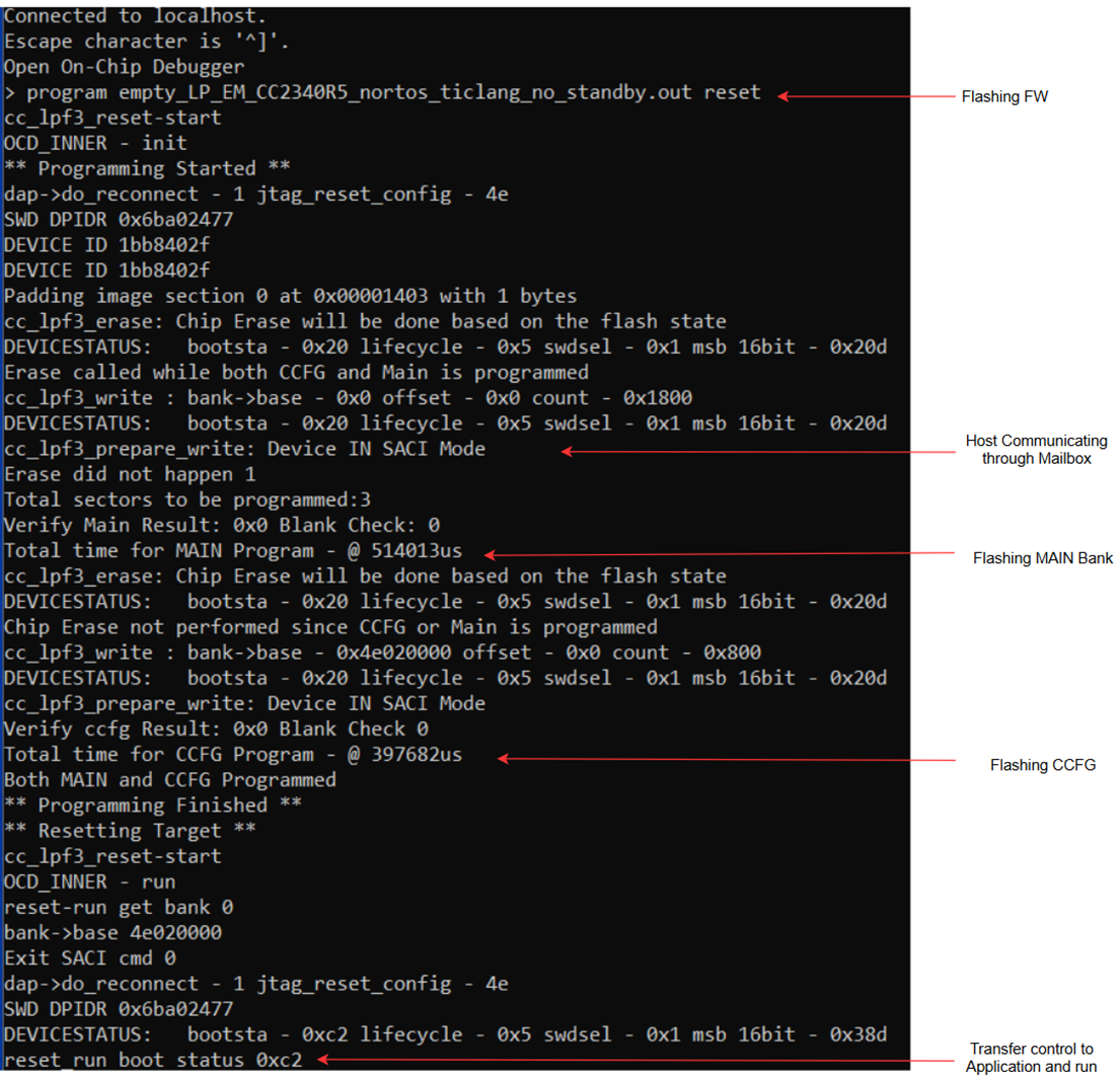
Example output for flashing a firmware using OpenOCD#
If the green LED of your board is blinking every second, then congratulations, you have successfully built your first Zephyr project on your LaunchPad !
UniFlash is a software created by Texas Instruments™ to flash devices. You can download UniFlash here.
Before opening UniFlash, you should connect your XDS110 with your computer using the USB-C to USB-A cable, and connect the XDS110 with the LaunchPad. This allows UniFlash to automatically detect the device upon being started. If your device was automatically detected, UniFlash should look like this, and you can click the Start button.
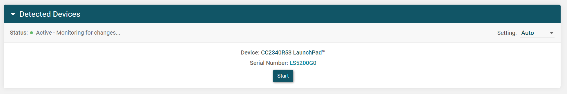
UniFlash automatically detecting a CC2340R53 LaunchPad#
If UniFlash did not automatically detect your LaunchPad, you can manually select your board by entering your device name, selecting it in the list and clicking the Start button.
Once you have selected your device, you can click the green Browse button,
and select the zephyr.hex file generated by Zephyr for the blinky sample in
the previous step. The zephyr.hex file is in the build/zephyr/ folder by
default. Your UniFlash should look something similar to this :
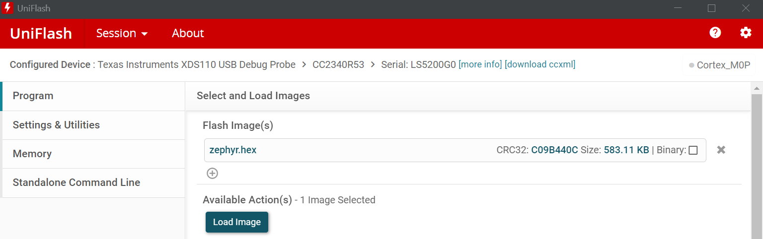
UniFlash main menu when flashing a Zephyr firmware#
You can then click Load Image to flash your LaunchPad with the blinky firmware. The final step is to power cycle the board (unplug and plug from the power source). If the green LED of your board is blinking every second, then congratulations, you have successfully built your first Zephyr project on your LaunchPad !
Currently the XDS110 debugger supplied with TI Launchpads is not natively supported in the west Zephyr tool for all devices. In order to flash/debug the CC2340R5 device with west, only J-Link is available. You can find J-Link’s download website here, or you can directly download the .deb for Debian and Ubuntu or the .rpm for Red Hat based distributions. The recommended version to use is V7.94f which has been used for validation.
If you are on Debian or Ubuntu, you can install the .deb file by running
sudo apt install /path/to/package.deb.
If you are on a Red Hat based distribution, you can install the .rpm file by
running sudo dnf install /path/to/package.rpm The recommended version to
use is V7.94f which has been used for validation.
Once the software is installed, in order to use J-Link, we need to connect the correct pins of the LaunchPad to the J-Link debug probe to send SWD signals, and the correct pins of the LaunchPad to the pins of the XDS110 to give the board power. We will connect them using jumper cables.
In order to help you to connect to the correct pins of the J-Link debug probe, here is the pinout of the debug probe :
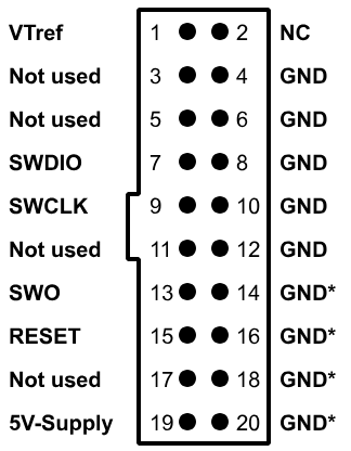
Pinout of the J-Link debug probe#
For the J-Link debug probe, the following pins must be connected :
Pin name on the LaunchPad |
Pin name on the J-Link debug probe |
|---|---|
|
|
|
|
|
|
|
|
|
|
In order to help you to connect to the correct pins of the XDS110, you can use the pinout printed under the XDS110.
For the XDS110 debugger, the following pins must be connected :
Pin name on the LaunchPad |
Pin name on the J-Link debug probe |
|---|---|
|
|
|
|
The final setup should look like this :
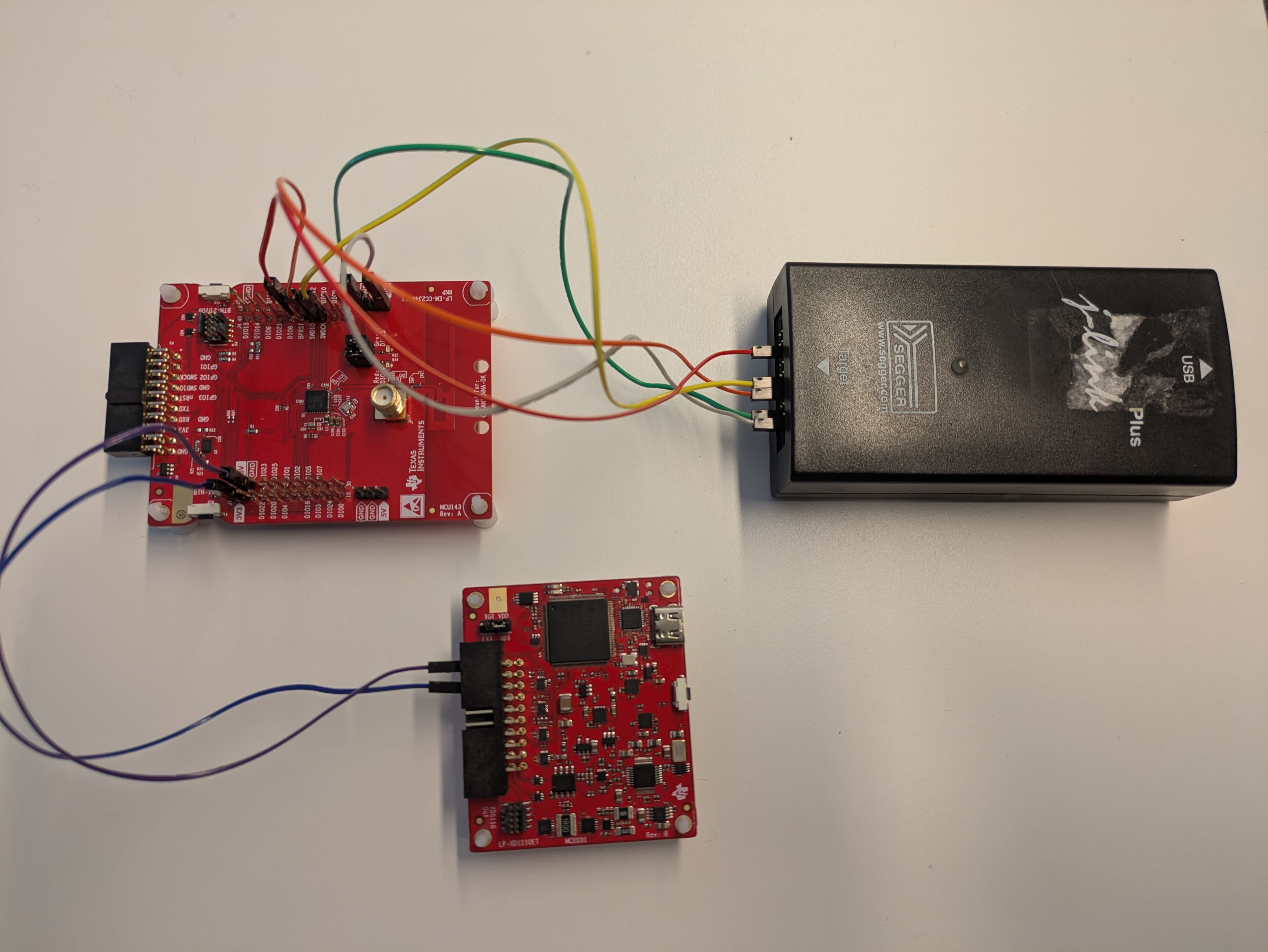
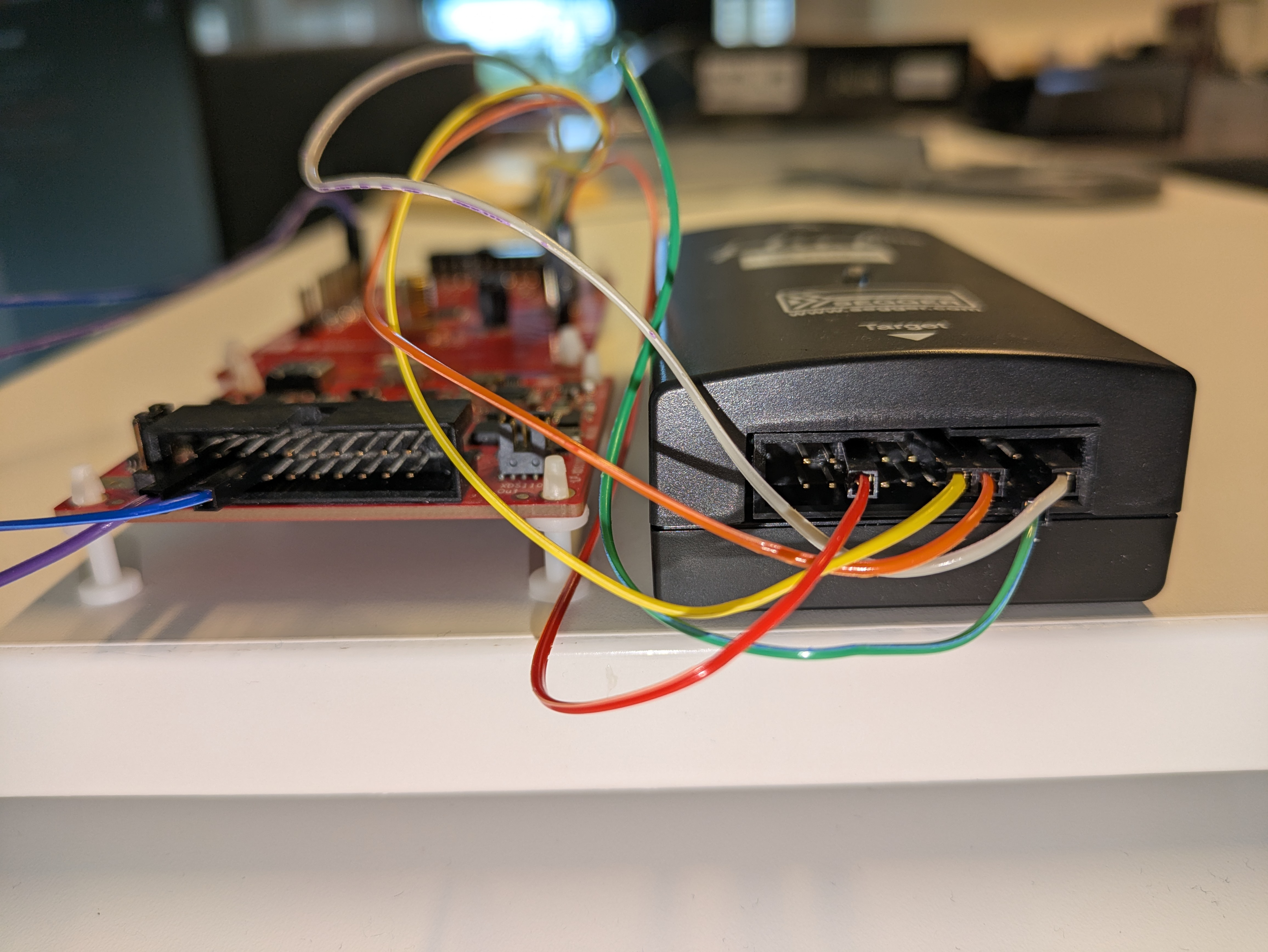
Final hardware wire of the J-Link and the XDS110 with the LaunchPad#
Now that everything is wired correctly, we can execute west flash in our
Zephyr environment. This will use the last firmware built with the west build
command to determine which to flash and how to flash it.
Some LaunchPads like the CC2340R53 are not recognized by the J-Link software. You can instead select a similar board like the CC2340R5.
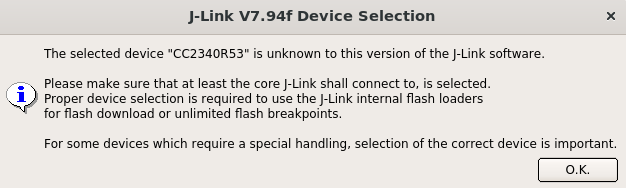
J-Link error when trying to flash a board not officially supported by J-Link#
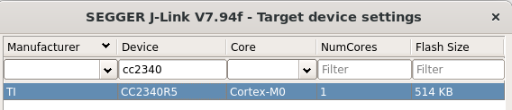
Example on how to select a similar board if the original one is not officially supported by J-Link#
You can find the list of all TI boards supported by J-Link and the versions in which they were added in the official list of supported devices by J-Link.
After a few seconds, the west flash command should successfully exit.
If the green LED of your board is blinking every second, then congratulations,
you have successfully built your first Zephyr project on your LaunchPad !
If the green LED of your board is not blinking, I would recommend you to try to perform a chip erase with Uniflash and restarting.
In addition to west flash, using J-Link gives access to the west debug
command, which will flash the firmware onto the board, and open a GDB server
from which the user can run GDB commands. As GDB is out of the scope of this
training, you can read more about GDB in
the man pages for GDB.