

|
|
Generic PIN & GPIO driver.
To use the PIN driver ensure that the correct TI-RTOS driver library for your device is linked in and include this header file:
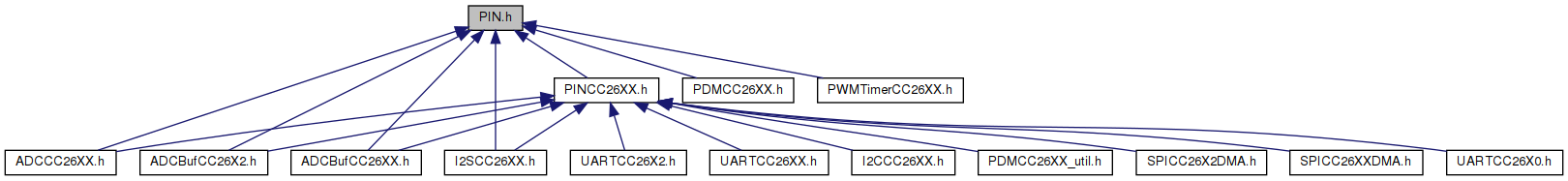
In order to use device-specific functionality or to use the size/speed- optimized versions of some of the PIN driver functions that circumvent error and resource checking, link in the correct TI-RTOS driver library for your device and include the device-specific PIN driver header file (which in turn includes PIN.h). As an example for the CC26xx family of devices:
The PIN driver allows clients (applications or other drivers) to allocate and control the I/O pins on the device. The pins can either be software- controlled general-purpose I/O (GPIO) or connected to hardware peripherals. Furthermore, the PIN driver allows clients to configure interrupt functionality on the pins to receive callbacks (and potentially wake up from the standby or idle power modes) on configurable signal edges.
Most other drivers rely on functionality in the PIN driver.
In order to provide a generic driver interface, this file (PIN.h) only defines the API and some common data types and macros of the driver. A PIN client (application or driver) can in most cases only use the generic PIN API, however, for more advanced usage where device-specific pin configuration is used or device-specific PIN driver API extensions are used must use the device-specific PIN driver API.
The device-independent API is implemented as function calls with pin access control based on the PIN client handle. For time-critical applications the device-specific API can be used directly, as these API functions are implemented as inlined functions without access control.
The PIN module provides the following functionality:
The purpose of being able to allocate pins to a pin set is to:
| API function | Description |
|---|---|
| PIN_open() | Allocate pins to a set, returns handle |
| PIN_add() | Add pin to pin set for open PIN handle |
| PIN_remove() | Removes pin from pin set for open PIN handle |
| PIN_close() | Deallocate pin set, revert to original GPIO state |
Pins that are to be used as software-controlled general-purpose I/O (GPIO) need to be allocated in the same manner as for pins that will be mapped to hardware peripheral ports. A pin set requested with a PIN_open() call may contain a mix of pins to be used for GPIO and hardware-mapped pins.
When a pin is deallocated using PIN_close() it reverts to the GPIO configuration it was given in the initial call to PIN_init().
| API function | Description |
|---|---|
| PIN_init() | Initialize I/O pins to a safe GPIO state |
| PIN_open() | Allocate pins to a set, returns handle |
| PIN_close() | Deallocate pin set, revert to original GPIO state |
| PIN_setConfig() | Sets parts of or complete pin configuration |
| PIN_getConfig() | Returns pin configuration |
| PIN_setOutputEnable() | Control output enable of GPIO pin |
| PIN_getInputValue() | Read input value on pin |
| PIN_setOutputValue() | Set output value of GPIO pin |
| PIN_getOutputValue() | Get current output value of GPIO pin |
Sometimes it is necessary to be able to read from, write to or control multiple pins simultaneously (in time). The PIN driver allows a set of allocated pins, if they reside on the same GPIO port in the underlying hardware, to be manipulated simultaneously.
| API function | Description |
|---|---|
| PIN_open() | Allocate pins to a set, returns handle |
| PIN_close() | Deallocate pin set, revert to original GPIO state |
| PIN_getPortMask() | Returns bitmask for allocated pins in GPIO port |
| PIN_getPortInputValue() | Returns input value of whole GPIO port |
| PIN_setPortOutputValue() | Sets output value of whole GPIO port (masked) |
| PIN_getPortOutputValue() | Get current output value of whole GPIO port |
| PIN_setPortOutputValue() | Sets output value of whole GPIO port (masked) |
| PIN_setPortOutputEnable() | Sets output enable of whole GPIO port (masked) |
Different devices provide different levels of configurability of I/O pins. The PIN driver provides a fairly extensive set of generic IO configuration options that are device-independent, all of which might not be supported by the underlying device-specific PIN driver and hardware. Likewise, the underlying device-specific PIN driver and hardware might support additional configuration options not covered by the generic options.
To allow both independence from and flexibility to use features on the target device, the PIN_Config entries used by the PIN driver allows use of either a set of generic PIN configuration options or a device-specific set of PIN configuration options defined in the underlying device-specific PIN driver (e.g. PINCC26XX.h)
Since the amount of flexibilty in which peripherals can be mapped to which pins and the manner in which this needs to be set up is highly device-specific, functions for configuring this is not part of the generic PIN driver API but is left to be implemented by device-specific PIN drivers. See the relevant device-specific PIN driver (e.g. PINCC26XX.h) for details.
The input mode of a pin controls:
| API function | Description |
|---|---|
| PIN_init() | Initialize IOs to a safe GPIO state |
| PIN_getConfig() | Returns pin configuration |
| PIN_setConfig() | Sets parts of or complete pin configuration |
The output mode of a pin controls:
| API function | Description |
|---|---|
| PIN_init() | Initialize IOs to a safe GPIO state |
| PIN_setOutputEnable() | Control output enable of GPIO pins |
| PIN_getConfig() | Returns pin configuration |
| PIN_setConfig() | Sets parts of or complete pin configuration |
Pin interrupts are used to process asynchronous signal edge events on pins and potentially wake the device up from low power sleep modes. To use pin interrupts the relevant pins must be allocated and a interrupt callback registered by the client. The callback function will be called in a SWI context.
| API function | Description |
|---|---|
| PIN_init() | Initialize IOs to a safe GPIO state |
| PIN_getConfig() | Returns pin configuration |
| PIN_setConfig() | Sets parts of or complete pin configuration |
| PIN_setInterrupt() | Control interrupt enable and edge for pin |
| PIN_registerIntCb() | Register callback function for a set of pins |
| PIN_setUserArg() | Sets a user argument associated with the handle |
| PIN_getUserArg() | Gets a user argument associated with the handle |
The PIN driver defines the following data types:
The PIN driver uses the PIN_Config data type many places and it merits some additional attention. A PIN_Config value consists of a collection of flags and fields that define how an I/O pin and its attached GPIO interface should behave electrically and logically. In addition a PIN_Config value also embeds a PIN_Id pin ID, identifying which pin it refers to.
A PIN_Config value can use one of two mutually exclusive sets of flags and fields: device-independent options defined in PIN.h or device-dependent options defined in the device-specific implementation of the PIN driver interface. Any function that uses PIN_Config will accept both option types, just not at the same time. PIN_getConfig() always returns device-independent options, an additional device-specific version (e.g. PINCC26XX_getConfig()) might return device-specific options.
The bitmask argument for PIN_setConfig() decides which of the options the call should affect. All other options are kept at their current values in hardware. Thus PIN_setConfig(hPins, PIN_BM_PULLING, PIN_BM_PULLUP) will only change the pullup/pulldown configuration of the pin, leaving everything else, such as for instance output enable, input hysteresis or output value, untouched. For PIN_Config lists (as supplied to PIN_init() for instance) there is no mask, so all options will affect the pin.
Some of the options affect the pin regardless of whether it is mapped to a hardware peripheral or GPIO and some options only take effect when it is mapped to GPIO. These latter options have _GPIO_ in their names.
The default value for a flag/field is indicated with a star (*) in the description of the options and will be applied if any explicit value is not supplied for a flag/field that is masked.
The available options can be grouped into categories as follows:
| Option | Option bitmask | HW/GPIO | Description |
|---|---|---|---|
| PIN_INPUT_EN (*) | PIN_BM_INPUT_EN | Both | Enable pin input buffer |
| PIN_INPUT_DIS | PIN_BM_INPUT_EN | Both | Disable pin input buffer |
| PIN_HYSTERESIS | PIN_BM_HYSTERESIS | Both | Enable hysteresis on input |
| PIN_NOPULL (*) | PIN_BM_PULLING | Both | No pullup/pulldown |
| PIN_PULLUP | PIN_BM_PULLING | Both | Enable pullup |
| PIN_PULLDOWN | PIN_BM_PULLING | Both | Enable pulldown |
| PIN_BM_INPUT_MODE | Mask for all input mode options |
| Option | Option bitmask | HW/GPIO | Description |
|---|---|---|---|
| PIN_GPIO_OUTPUT_DIS (*) | PIN_BM_GPIO_OUTPUT_EN | GPIO | Disable GPIO output buffer |
| PIN_GPIO_OUTPUT_EN | PIN_BM_GPIO_OUTPUT_EN | GPIO | Enable GPIO output buffer |
| PIN_GPIO_LOW (*) | PIN_BM_GPIO_OUTPUT_VAL | GPIO | Output 0 when GPIO |
| PIN_GPIO_HIGH | PIN_BM_GPIO_OUTPUT_VAL | GPIO | Output 1 when GPIO |
| PIN_PUSHPULL (*) | PIN_BM_OUTPUT_BUF | Both | Use push-pull output buffer |
| PIN_OPENDRAIN | PIN_BM_OUTPUT_BUF | Both | Use open drain output buffer |
| PIN_OPENSOURCE | PIN_BM_OUTPUT_BUF | Both | Use open source output buffer |
| PIN_SLEWCTRL | PIN_BM_SLEWCTRL | Both | Enable output buffer slew control |
| PIN_DRVSTR_MIN (*) | PIN_BM_DRVSTR | Both | Output buffer uses min drive |
| PIN_DRVSTR_MED | PIN_BM_DRVSTR | Both | Output buffer uses medium drive |
| PIN_DRVSTR_MAX | PIN_BM_DRVSTR | Both | Output buffer uses max drive |
| PIN_BM_OUTPUT_MODE | Mask for all output mode options |
| Option | Option bitmask | HW/GPIO | Description |
|---|---|---|---|
| PIN_INV_INOUT | PIN_BM_INV_INOUT | Both | Invert input/output |
| PIN_IRQ_DIS (*) | PIN_BM_IRQ | Both | Disable pin interrupts |
| PIN_IRQ_NEGEDGE | PIN_BM_IRQ | Both | Pin interrupts on negative edges |
| PIN_IRQ_POSEDGE | PIN_BM_IRQ | Both | Pin interrupts on negative edges |
| PIN_IRQ_BOTHEDGES | PIN_BM_IRQ | Both | Pin interrupts on both edges |
| PIN_BM_ALL | Mask for all options |
The PIN driver must be initialized before any other drivers are initialized. In order for IO pins to get a safe value as soon as possible PIN_init() should be called as early as possible in the boot sequence. Typically, PIN_init() is called at the start of main() before TI-RTOS is started with BIOS_start().
PIN_init() takes as an argument a PIN_Config list containing default pin configurations. Typically the PIN_Config list defined in the board files is used:
It is possible, however, to use another PIN_Config list if desired.
No specific interaction with power management module, as PIN is independent of power mode.
There is no known unsupported functionality.
The pin driver does not use any of the instrumentation facilities.
Example that illustrates when and how to call PIN_init(), PIN_open(), PIN_add(), PIN_close()
An example of using GPIO that builds on the previous example. Illustrates how to read input values, set output values and control output enable
An example that handles pin inputs in the GPIO example above using PIN interrupts instead:
#include <stdbool.h>#include <stdint.h>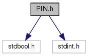
Go to the source code of this file.
Data Structures | |
| struct | PIN_State_s |
| underlying data structure for type PIN_State More... | |
Macros | |
| #define | PIN_UNASSIGNED 0xFF |
| Pin ID used to indicate no pin. More... | |
| #define | PIN_TERMINATE 0xFE |
| Pin ID used to terminate a list of PIN_Id or PIN_Config entries. More... | |
| #define | PIN_ID(x) ((x)&0xFF) |
| Macro for inserting or extracting a PIN_Id in a PIN_Config entry. More... | |
Generic PIN_Config flags/fields | |
Generic (i.e. not device-specific) fields/flags for I/O configuration for use in PIN_Config entries. All of these generic options may not be supported by the underlying device-specific PIN driver. A PIN_Config entry may use either these generic fields/flags or device-specific ones defined in the device-specific PIN-driver, but may not mix the two. The entries starting with PIN_BM_ are bitmasks used to extract individual fields obtained from PIN_getConfig() or to pass as a parameter to PIN_setConfig()to define which options it should set. A star (*) in the descriptions below means the default if no option is supplied. | |
| #define | PIN_GEN (((uint32_t)1) << 31) |
| Flags that generic options are used. More... | |
| #define | PIN_INPUT_EN (PIN_GEN | (0 << 29)) |
| (*) Enable input buffer More... | |
| #define | PIN_INPUT_DIS (PIN_GEN | (1 << 29)) |
| Disable input buffer. More... | |
| #define | PIN_HYSTERESIS (PIN_GEN | (1 << 30)) |
| Enable input buffer hysteresis. More... | |
| #define | PIN_NOPULL (PIN_GEN | (0 << 13)) |
| (*) No pull-up or pull-down resistor More... | |
| #define | PIN_PULLUP (PIN_GEN | (1 << 13)) |
| Pull-up resistor enabled. More... | |
| #define | PIN_PULLDOWN (PIN_GEN | (2 << 13)) |
| Pull-down resistor enabled. More... | |
| #define | PIN_BM_INPUT_EN (1 << 29) |
| Bitmask for input enable option. More... | |
| #define | PIN_BM_HYSTERESIS (1 << 30) |
| Bitmask input hysteresis option. More... | |
| #define | PIN_BM_PULLING (0x3 << 13) |
| Bitmask for pull-up/pull-down options. More... | |
| #define | PIN_BM_INPUT_MODE (PIN_BM_INPUT_EN|PIN_BM_HYSTERESIS|PIN_BM_PULLING) |
| Bitmask for all input mode options. More... | |
| #define | PIN_GPIO_OUTPUT_DIS (PIN_GEN | (0 << 23)) |
| (*) Disable output buffer when GPIO More... | |
| #define | PIN_GPIO_OUTPUT_EN (PIN_GEN | (1 << 23)) |
| Enable output buffer when GPIO. More... | |
| #define | PIN_GPIO_LOW (PIN_GEN | (0 << 22)) |
| Output buffer drives to VSS when GPIO. More... | |
| #define | PIN_GPIO_HIGH (PIN_GEN | (1 << 22)) |
| Output buffer drives to VDD when GPIO. More... | |
| #define | PIN_PUSHPULL (PIN_GEN | (0 << 25)) |
| (*) Output buffer mode: push/pull More... | |
| #define | PIN_OPENDRAIN (PIN_GEN | (2 << 25)) |
| Output buffer mode: open drain. More... | |
| #define | PIN_OPENSOURCE (PIN_GEN | (3 << 25)) |
| Output buffer mode: open source. More... | |
| #define | PIN_SLEWCTRL (PIN_GEN | (1 << 12)) |
| Enable output buffer slew control. More... | |
| #define | PIN_DRVSTR_MIN (PIN_GEN | (0x0 << 8)) |
| (*) Lowest drive strength More... | |
| #define | PIN_DRVSTR_MED (PIN_GEN | (0x4 << 8)) |
| Medium drive strength. More... | |
| #define | PIN_DRVSTR_MAX (PIN_GEN | (0x8 << 8)) |
| Highest drive strength. More... | |
| #define | PIN_BM_GPIO_OUTPUT_EN (1 << 23) |
| Bitmask for output enable option. More... | |
| #define | PIN_BM_GPIO_OUTPUT_VAL (1 << 22) |
| Bitmask for output value option. More... | |
| #define | PIN_BM_OUTPUT_BUF (0x3 << 25) |
| Bitmask for output buffer options. More... | |
| #define | PIN_BM_SLEWCTRL (0x1 << 12) |
| Bitmask for slew control options. More... | |
| #define | PIN_BM_DRVSTR (0xF << 8) |
| Bitmask for drive strength options. More... | |
| #define | PIN_BM_OUTPUT_MODE |
| Bitmask for all output mode options. More... | |
| #define | PIN_INV_INOUT (PIN_GEN | (1 << 24)) |
| Logically invert input and output. More... | |
| #define | PIN_BM_INV_INOUT (1 << 24) |
| Bitmask for input/output inversion option. More... | |
| #define | PIN_IRQ_DIS (PIN_GEN | (0x0 << 16)) |
| (*) Disable IRQ on pin More... | |
| #define | PIN_IRQ_NEGEDGE (PIN_GEN | (0x5 << 16)) |
| Enable IRQ on negative edge. More... | |
| #define | PIN_IRQ_POSEDGE (PIN_GEN | (0x6 << 16)) |
| Enable IRQ on positive edge. More... | |
| #define | PIN_IRQ_BOTHEDGES (PIN_GEN | (0x7 << 16)) |
| Enable IRQ on both edges. More... | |
| #define | PIN_BM_IRQ (0x7 << 16) |
| Bitmask for pin interrupt option. More... | |
| #define | PIN_BM_ALL (PIN_BM_INPUT_MODE | PIN_BM_OUTPUT_MODE | PIN_BM_INV_INOUT | PIN_BM_IRQ) |
| Bitmask for all options at once. More... | |
Typedefs | |
| typedef uint8_t | PIN_Id |
| Pin identifier data type. More... | |
| typedef uint32_t | PIN_Config |
| Pin configuration data type with embedded pin identifier. More... | |
| typedef struct PIN_State_s | PIN_State |
| Struct used to store PIN client state Pointer to a PIN_State is used as handles (PIN_Handle) in interactions with the I/O driver. More... | |
| typedef PIN_State * | PIN_Handle |
| A handle that is returned from a PIN_open() call Used for further PIN client interaction with the PIN driver. More... | |
| typedef void(* | PIN_IntCb) (PIN_Handle handle, PIN_Id pinId) |
| I/O Interrupt callback function pointer type One PIN Interrupt callback can be registered by each PIN client and it will be called when one of the pins allocated by the client has an interrupt event. The callback is called from HWI context with handle and pin ID as arguments. More... | |
Enumerations | |
| enum | PIN_Status { PIN_SUCCESS = 0, PIN_ALREADY_ALLOCATED = 1, PIN_NO_ACCESS = 2, PIN_UNSUPPORTED = 3 } |
| Return value for many functions in the PIN driver interface. More... | |
Functions | |
| PIN_Status | PIN_init (const PIN_Config aPinCfg[]) |
| PIN module initialization. More... | |
| PIN_Handle | PIN_open (PIN_State *state, const PIN_Config pinList[]) |
| Allocate one or more pins for a driver or an application. More... | |
| PIN_Status | PIN_add (PIN_Handle handle, PIN_Config pinCfg) |
| Add pin to pin set for open PIN handle. More... | |
| PIN_Status | PIN_remove (PIN_Handle handle, PIN_Id pinId) |
| Removes pin from pin set foropen PIN handle. More... | |
| void | PIN_close (PIN_Handle handle) |
| Deallocate all pins previously allocated with a call to PIN_open(). More... | |
| static void | PIN_setUserArg (PIN_Handle handle, uintptr_t arg) |
| Sets a user argument associated with the handle. More... | |
| static uintptr_t | PIN_getUserArg (PIN_Handle handle) |
| Gets a user argument associated with the handle. More... | |
Pin Manipulation/Configuration Functions | |
Functions that are used to manipulate the configuration of I/O pins and to get input values and set output values. | |
| uint32_t | PIN_getInputValue (PIN_Id pinId) |
| Get pin input value (0/1) More... | |
| PIN_Status | PIN_setOutputEnable (PIN_Handle handle, PIN_Id pinId, bool outputEnable) |
| Control output enable for GPIO pin. More... | |
| PIN_Status | PIN_setOutputValue (PIN_Handle handle, PIN_Id pinId, uint32_t val) |
| Control output value for GPIO pin. More... | |
| uint32_t | PIN_getOutputValue (PIN_Id pinId) |
| Get value of GPIO pin output buffer. More... | |
| PIN_Status | PIN_setInterrupt (PIN_Handle handle, PIN_Config pinCfg) |
| Control interrupt enable and edge for pin. More... | |
| PIN_Status | PIN_clrPendInterrupt (PIN_Handle handle, PIN_Id pinId) |
| Clear pending interrupt for pin, if any. More... | |
| PIN_Status | PIN_registerIntCb (PIN_Handle handle, PIN_IntCb callbackFxn) |
| Register callback function for a set of pins. More... | |
| PIN_Config | PIN_getConfig (PIN_Id pinId) |
| Returns pin configuration. More... | |
| PIN_Status | PIN_setConfig (PIN_Handle handle, PIN_Config updateMask, PIN_Config pinCfg) |
| Sets complete pin configuration. More... | |
IO Port Functions | |
Functions used to get input values for, set ouput values for and set output enables for multiple pins at a time. The size of so-called I/O ports that allows such multiple-pin operations are highly device dependent. In order to use the I/O port functions a set of pins that reside in the same I/O port must have been allocated previously with PIN_open(). | |
| uint32_t | PIN_getPortMask (PIN_Handle handle) |
| Returns bitmask indicating pins allocated to client in GPIO port. More... | |
| uint32_t | PIN_getPortInputValue (PIN_Handle handle) |
| Read input value of whole GPIO port. More... | |
| uint32_t | PIN_getPortOutputValue (PIN_Handle handle) |
| Returns value of whole GPIO port's output buffers. More... | |
| PIN_Status | PIN_setPortOutputValue (PIN_Handle handle, uint32_t outputValueMask) |
| Simultaneous write output buffer values of all allocated pins in GPIO port. More... | |
| PIN_Status | PIN_setPortOutputEnable (PIN_Handle handle, uint32_t outputEnableMask) |
| Set output enable for all pins allocated to client in GPIO port. More... | |
| #define PIN_UNASSIGNED 0xFF |
Pin ID used to indicate no pin.
| #define PIN_TERMINATE 0xFE |
Pin ID used to terminate a list of PIN_Id or PIN_Config entries.
| #define PIN_ID | ( | x | ) | ((x)&0xFF) |
Macro for inserting or extracting a PIN_Id in a PIN_Config entry.
| #define PIN_GEN (((uint32_t)1) << 31) |
Flags that generic options are used.
| #define PIN_INPUT_EN (PIN_GEN | (0 << 29)) |
(*) Enable input buffer
| #define PIN_INPUT_DIS (PIN_GEN | (1 << 29)) |
Disable input buffer.
| #define PIN_HYSTERESIS (PIN_GEN | (1 << 30)) |
Enable input buffer hysteresis.
| #define PIN_NOPULL (PIN_GEN | (0 << 13)) |
(*) No pull-up or pull-down resistor
| #define PIN_PULLUP (PIN_GEN | (1 << 13)) |
Pull-up resistor enabled.
| #define PIN_PULLDOWN (PIN_GEN | (2 << 13)) |
Pull-down resistor enabled.
| #define PIN_BM_INPUT_EN (1 << 29) |
Bitmask for input enable option.
| #define PIN_BM_HYSTERESIS (1 << 30) |
Bitmask input hysteresis option.
| #define PIN_BM_PULLING (0x3 << 13) |
Bitmask for pull-up/pull-down options.
| #define PIN_BM_INPUT_MODE (PIN_BM_INPUT_EN|PIN_BM_HYSTERESIS|PIN_BM_PULLING) |
Bitmask for all input mode options.
| #define PIN_GPIO_OUTPUT_DIS (PIN_GEN | (0 << 23)) |
(*) Disable output buffer when GPIO
| #define PIN_GPIO_OUTPUT_EN (PIN_GEN | (1 << 23)) |
Enable output buffer when GPIO.
| #define PIN_GPIO_LOW (PIN_GEN | (0 << 22)) |
Output buffer drives to VSS when GPIO.
| #define PIN_GPIO_HIGH (PIN_GEN | (1 << 22)) |
Output buffer drives to VDD when GPIO.
| #define PIN_PUSHPULL (PIN_GEN | (0 << 25)) |
(*) Output buffer mode: push/pull
| #define PIN_OPENDRAIN (PIN_GEN | (2 << 25)) |
Output buffer mode: open drain.
| #define PIN_OPENSOURCE (PIN_GEN | (3 << 25)) |
Output buffer mode: open source.
| #define PIN_SLEWCTRL (PIN_GEN | (1 << 12)) |
Enable output buffer slew control.
| #define PIN_DRVSTR_MIN (PIN_GEN | (0x0 << 8)) |
(*) Lowest drive strength
| #define PIN_DRVSTR_MED (PIN_GEN | (0x4 << 8)) |
Medium drive strength.
| #define PIN_DRVSTR_MAX (PIN_GEN | (0x8 << 8)) |
Highest drive strength.
| #define PIN_BM_GPIO_OUTPUT_EN (1 << 23) |
Bitmask for output enable option.
| #define PIN_BM_GPIO_OUTPUT_VAL (1 << 22) |
Bitmask for output value option.
| #define PIN_BM_OUTPUT_BUF (0x3 << 25) |
Bitmask for output buffer options.
| #define PIN_BM_SLEWCTRL (0x1 << 12) |
Bitmask for slew control options.
| #define PIN_BM_DRVSTR (0xF << 8) |
Bitmask for drive strength options.
| #define PIN_BM_OUTPUT_MODE |
Bitmask for all output mode options.
| #define PIN_INV_INOUT (PIN_GEN | (1 << 24)) |
Logically invert input and output.
| #define PIN_BM_INV_INOUT (1 << 24) |
Bitmask for input/output inversion option.
| #define PIN_IRQ_DIS (PIN_GEN | (0x0 << 16)) |
(*) Disable IRQ on pin
| #define PIN_IRQ_NEGEDGE (PIN_GEN | (0x5 << 16)) |
Enable IRQ on negative edge.
| #define PIN_IRQ_POSEDGE (PIN_GEN | (0x6 << 16)) |
Enable IRQ on positive edge.
| #define PIN_IRQ_BOTHEDGES (PIN_GEN | (0x7 << 16)) |
Enable IRQ on both edges.
| #define PIN_BM_IRQ (0x7 << 16) |
Bitmask for pin interrupt option.
| #define PIN_BM_ALL (PIN_BM_INPUT_MODE | PIN_BM_OUTPUT_MODE | PIN_BM_INV_INOUT | PIN_BM_IRQ) |
Bitmask for all options at once.
| typedef uint8_t PIN_Id |
Pin identifier data type.
Data type used to identify a pin through an index between 0 to 254. Typically the index does not refer to the physical device pin number but rather to the index of the subset of pins that are under software-control (e.g. index 3 refers to DIO3). This data type is used as arguments in API functions to identify which pin is affected or used in lists (terminated by PIN_TERMINATE entry) identifying multiple pins
| typedef uint32_t PIN_Config |
Pin configuration data type with embedded pin identifier.
A data type used to specify I/O-pin configuration options. The lower 8b contain an embedded pin ID (see PIN_Id) and the top 24b contain flags/fields that affect I/O configuration. PIN_Config entries can either use a set of device-independent options or device-specific options defined in PIN driver (e.g. PINCC26XX.h), but cannot mix the two.
This data type is used as arguments or return values in API functions that manipulate pin configuration or used in lists (terminated by a PIN_TERMINATE entry) for configuring multiple pins at a time.
| typedef struct PIN_State_s PIN_State |
Struct used to store PIN client state Pointer to a PIN_State is used as handles (PIN_Handle) in interactions with the I/O driver.
| typedef PIN_State* PIN_Handle |
A handle that is returned from a PIN_open() call Used for further PIN client interaction with the PIN driver.
| typedef void(* PIN_IntCb) (PIN_Handle handle, PIN_Id pinId) |
I/O Interrupt callback function pointer type One PIN Interrupt callback can be registered by each PIN client and it will be called when one of the pins allocated by the client has an interrupt event. The callback is called from HWI context with handle and pin ID as arguments.
| enum PIN_Status |
| PIN_Status PIN_init | ( | const PIN_Config | aPinCfg[] | ) |
PIN module initialization.
Must be called early in the boot sequence to ensure that I/O pins have safe configurations. This initialization sets up pins as GPIO as defined in an array (possibly user-generated) that typically resides in a board file. All pins not mentioned in aPinCfg[] are configured to be input/output/pull disabled.
| aPinCfg[] | Pointer to array of PIN_Config entries, one per pin that needs configuration. List terminates when a PIN_TERMINATE entry is encountered. |
| PIN_Handle PIN_open | ( | PIN_State * | state, |
| const PIN_Config | pinList[] | ||
| ) |
Allocate one or more pins for a driver or an application.
Allows a PIN client (driver or application) to allocate a set of pins, thus ensuring that they cannot be reconfigured/controlled by anyone else. The pins are identified by and reconfigured according to the PIN_Config entries in pinList.
| state | Pointer to a PIN_State object that will hold the state for this IO client. The object must be in persistent memory |
| pinList[] | Pointer to array of PIN_Config entries, one per pin to allocate. List terminates when PIN_TERMINATE entry is encountered. |
| PIN_Status PIN_add | ( | PIN_Handle | handle, |
| PIN_Config | pinCfg | ||
| ) |
Add pin to pin set for open PIN handle.
If the requested pin is unallocated it will be added, else an error code will be returned.
| handle | handle retrieved through an earlier call to PIN_open(). |
| pinCfg | Pin ID/configuration for pin to add. |
| PIN_Status PIN_remove | ( | PIN_Handle | handle, |
| PIN_Id | pinId | ||
| ) |
Removes pin from pin set foropen PIN handle.
If the requested pin is allocated to handle it will be removed from the pin set, else an error code will be returned.
| handle | handle retrieved through an earlier call to PIN_open(). |
| pinId | Pin ID for pin to remove. |
| void PIN_close | ( | PIN_Handle | handle | ) |
Deallocate all pins previously allocated with a call to PIN_open().
Deallocate pins allocated to handle and restore these pins to the pool of unallocated pins. Also restores the pin configuration to what it was set to when PIN_init() was called.
| handle | handle retrieved through an earlier call to PIN_open(). |
|
inlinestatic |
Sets a user argument associated with the handle.
Allows the application to store some data, for example a pointer to some data structure, with each PIN handle
| handle | handle retrieved through an earlier call to PIN_open(). |
| arg | User argument |
|
inlinestatic |
Gets a user argument associated with the handle.
Allows the application to store some data, for example a pointer to some data structure, with each PIN handle
| handle | handle retrieved through an earlier call to PIN_open(). |
| uint32_t PIN_getInputValue | ( | PIN_Id | pinId | ) |
Get pin input value (0/1)
Input values of all pins are available to everyone so no handle required
| pinId | ID of pin to get input value from |
| PIN_Status PIN_setOutputEnable | ( | PIN_Handle | handle, |
| PIN_Id | pinId, | ||
| bool | outputEnable | ||
| ) |
Control output enable for GPIO pin.
| handle | Handle provided by previous call to PIN_open() |
| pinId | PIN_Id entry identifying pin |
| outputEnable | Enable output buffer when true, else disable |
| PIN_Status PIN_setOutputValue | ( | PIN_Handle | handle, |
| PIN_Id | pinId, | ||
| uint32_t | val | ||
| ) |
Control output value for GPIO pin.
| handle | Handle provided by previous call to PIN_open() |
| pinId | Pin ID |
| val | Output value (0/1) |
| uint32_t PIN_getOutputValue | ( | PIN_Id | pinId | ) |
Get value of GPIO pin output buffer.
Output values of all pins are available to everyone so no handle required
| pinId | Pin ID |
| PIN_Status PIN_setInterrupt | ( | PIN_Handle | handle, |
| PIN_Config | pinCfg | ||
| ) |
Control interrupt enable and edge for pin.
| handle | Handle provided by previous call to PIN_open() |
| pinCfg | PIN_Config entry identifying pin ID and relevant pin configuration as combinations of: |
| PIN_Status PIN_clrPendInterrupt | ( | PIN_Handle | handle, |
| PIN_Id | pinId | ||
| ) |
Clear pending interrupt for pin, if any.
| handle | Handle provided by previous call to PIN_open() |
| pinId | PIN_Id for pin to clear pending interrupt for |
| PIN_Status PIN_registerIntCb | ( | PIN_Handle | handle, |
| PIN_IntCb | callbackFxn | ||
| ) |
Register callback function for a set of pins.
Registers a callback function (see PIN_IntCb for details) for the client identified by handle that will be called from HWI context upon an interrupt event on one or more of the allocated pins that have interrupts enabled
| handle | Handle provided by previous call to PIN_open() |
| callbackFxn | Function pointer to a PIN_IntCb function. |
| PIN_Config PIN_getConfig | ( | PIN_Id | pinId | ) |
Returns pin configuration.
| pinId | Pin ID |
| PIN_Status PIN_setConfig | ( | PIN_Handle | handle, |
| PIN_Config | updateMask, | ||
| PIN_Config | pinCfg | ||
| ) |
Sets complete pin configuration.
| handle | Handle provided by previous call to PIN_open() |
| updateMask | Bitmask specifying which fields in cfg that should take effect, the rest keep their current value. |
| pinCfg | PIN_Config entry with pin ID and pin configuration |
| uint32_t PIN_getPortMask | ( | PIN_Handle | handle | ) |
Returns bitmask indicating pins allocated to client in GPIO port.
| handle | Handle provided by previous call to PIN_open() |
| uint32_t PIN_getPortInputValue | ( | PIN_Handle | handle | ) |
Read input value of whole GPIO port.
| handle | Handle provided by previous call to PIN_open() |
| uint32_t PIN_getPortOutputValue | ( | PIN_Handle | handle | ) |
Returns value of whole GPIO port's output buffers.
The I/O port is identified by the pins allocated by client in a previous call to PIN_open()
| handle | Handle provided by previous call to PIN_open() |
| PIN_Status PIN_setPortOutputValue | ( | PIN_Handle | handle, |
| uint32_t | outputValueMask | ||
| ) |
Simultaneous write output buffer values of all allocated pins in GPIO port.
| handle | Handle provided by previous call to PIN_open() |
| outputValueMask | Bitmask indicating the desired output value for the whole port, only the pins allocated to the client will be affected |
| PIN_Status PIN_setPortOutputEnable | ( | PIN_Handle | handle, |
| uint32_t | outputEnableMask | ||
| ) |
Set output enable for all pins allocated to client in GPIO port.
| handle | Handle provided by previous call to PIN_open() |
| outputEnableMask | Bitmask indicating the desired output enable configuration for the whole port, only the pins allocated to the client will be affected |