Common User Interface
It is recommended to use PuTTY as the serial terminal program for these sample applications because the serial output has been verified to be formatted correctly in this program. For serial port setup, select 115200 for baud rate and disable flow control.
The user interface allows to control the network configuration as well as
application behavior. The network interface is common for all
applications and is implemented in the module ssf.c on the sensor application
and csf.c on the collector application.
The application specifics of the serial interface is implemented in its respective application files.
The user interface consists of a series of circular menus that are navigated with the arrow keys. Pressing the Enter key will enter submenu. Use the up and down arrow keys to change the parameters on the menu (eg. channel mask, PAN ID, install codes, etc.).
The common user interface is also dependent on the capabilities of the compiled device, e.g. Collector devices (coordinators) will be able to open/close the network, whereas sensor devices will only require to start the sensor.
The common user interface also allows interaction with the specific application menu system under the App menu screen.
Welcome and <Help> Screens
The Welcome Screen (Figure 27.) displays the application name and leads to the Help Screen (Figure 28.), which outlines the generic functionality of the keys throughout the application. The following sections describe the specific functionality of the keys for each menu screen.
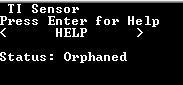
Figure 27. Welcome screen
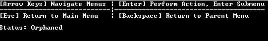
Figure 28. Help screen
Welcome and Help Screens |
||
|---|---|---|
Key |
Functionality |
Comment |
Left/Right Arrow Keys |
Menu navigation |
Move to previous/next screen |
Enter |
Help |
Press Enter to show the help screen, press Enter again to go back to the Welcome Screen |
Information Screen
The lower portion of the screen (Figure 29.) displays various information about the device. about the device such as the IEEE address, the PAN ID, the channel, short address, logical device type, and the parent short address.

Figure 29. Info screen example
Status
The Device Info field shows information about the device (e.g. Waiting, starting, started, joined, orphaned, etc.).
Mode:
NBCN - Non-Beacon Mode
BCN - Beacon Mode
FH - Frequency Hopping Mode
Addr:
Device Short Address (Assigned by the Collector device)
PanId:
16-bit PAN ID which this device is part of
Ch:
Logical channel of the network
PermitJoin (On Collector devices only):
Status of the network, is it open or closed.
Device Status
The Device Status line will show the latest information coming in, for example if the sensor just reported its temperature you will see it in this line like so (Figure 30.).
This message is modifiable to show what your application needs, but below you can see the default view for a temperature sensor.
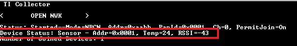
Figure 30. Device Status example
Addr
16-bit NWK address of the device
Temp:
Internal temperature of your sensor device
RSSI:
Received Signal Strength Indicator.
Number of Joined Devices
The number of devices currently connected to the NWK.
<Configure> Menu
The Configure Menu (Figure 31.) contains several sub-menus that allow the user to manipulate the NWK Key, channel masks and PAN ID. This configuration will define the device behavior during BDB commissioning procedures.

Figure 31. Configure Menu
Channel Mask Screen
The Channel Mask Screen (Figure 32.) display and allow modification of the default channel configuration of the device for channel mask. Channel mask is a Bit-Masked value, for example if you have 0F 00 00 00 it means you have channels 0-3 enabled, or if you have F0 0F 00 00 it means you have channels 4-11 enabled. Press the Enter key to start changing the mask, highlight the value you want to modify and type in the value you want in Hex (0-F).
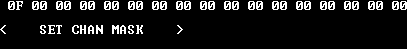
Figure 32. Channel Mask Screen
<Channel Mask> – view mode |
||
|---|---|---|
Key |
Functionality |
Comment |
Left/Right |
Menu navigation |
Move to previous/next screen |
Enter |
Select |
Enter edit mode |
<Channel Mask> – edit mode |
||
|---|---|---|
Key |
Functionality |
Comment |
Left/Right |
Menu navigation |
Move to previous/next screen |
Enter |
Select |
Enter edit mode |
0-F |
Modify Value |
Modify Channel Mask |
<PAN ID> Screen
The PAN ID Screen (Figure 33.) allows changing of the default PAN ID (0xFFFF by default) to any desired value.

Figure 33. PAN ID Screen - view mode
<PAN ID> Screen – view mode |
||
|---|---|---|
Key |
Functionality |
Comment |
Left/Right |
Menu navigation |
Move to previous/next screen |
Enter |
Select |
Enter edit mode |
<PAN ID> Screen – edit mode |
||
|---|---|---|
Key |
Functionality |
Comment |
Left/Right |
Digit navigation |
Move to previous/next digit |
0-F |
Value change |
Change the value of the highlighted digit |
Enter |
Select |
Save and exit mode |
Set NWK Key
The SET NWK KEY Screen (Figure 34.) allows changing of the default NWK Security Key to any desired value.
Note
That the device will need to have been flashed with the secured Lib (CCS does this by default), and both the sensor and collector device must share the NWK Key.
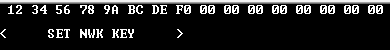
Figure 34. SET-NWK-KEY Screen - view mode
<Set NWK Key> Screen – view mode |
||
|---|---|---|
Key |
Functionality |
Comment |
Left/Right |
Menu navigation |
Move to previous/next screen |
Enter |
Select |
Enter edit mode |
<Set NWK Key> Screen – edit mode |
||
|---|---|---|
Key |
Functionality |
Comment |
Left/Right |
Digit navigation |
Move to previous/next digit |
0-F |
Value change |
Change the value of the highlighted digit |
Enter |
Select |
Save and exit mode |
Network Actions
The Network actions Screens (Figure 35., Figure 36., Figure 37., Figure 38., Figure 39., Figure 40.)allow enabling/disabling of the top level commissioning procedures that will be performed when the collector and sensor devices have started and ready to join a network.
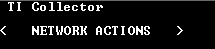
Figure 35. Network-Actions Screen
FORM NWK
The FORM NWK action is available for a collector device of our 15.4 Stack network. This actions will allow the collector to start the network, it is the first step to get TI15.4 stack network going.
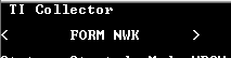
Figure 36. FORM-NWK Screen
OPEN NWK
The OPEN NWK action is available for a collector device of our 15.4 Stack network. This actions will allow the collector to open the network after being started, it is the second step to get TI15.4 stack network going, at this point a sensor device will be able to join.

Figure 37. OPEN-NWK Screen
CLOSE NWK
The CLOSE NWK action is available for a collector device of our 15.4 Stack network. This actions will allow the collector to close the network after being opened, it is used when the collector will no longer accept new connections in the network.
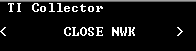
Figure 38. CLOSE-NWK Screen
ASSOCIATE
The Associate action is available for a sensor device of our 15.4 Stack network. This actions will allow the sensor to scan and look for a network after being opened, it is used when the collector has already started a network and opened the network to new connections.

Figure 39. ASSOCIATE Screen

<Back> Screen
The Back Screen (Figure 41.) allows returning to the previous screen. When the back action is performed the upper level screen will be displayed automatically.

Figure 41. Back Screen
<Back> Screen |
||
|---|---|---|
Key |
Functionality |
Comment |
Left/Right |
Menu navigation |
Move to previous/next screen |
Enter |
Select |
Back to upper menu |
<App> Menu
The App menu (Figure 42.) is application specific and will contain the menus to interact with the specific application implementation. Those specific application menus are explained in the README documentation provided by each application and referred in Example Applications.
This menu is intended to be used once the device is already associated to a network, as it provides ways to interact with the other devices in the network. For example, the Collector application will have a Send Toggle interface which will trigger the Sensor application Toggle its RED LED.

Figure 42. App Screen
<App> Menu |
||
|---|---|---|
Key |
Functionality |
Comment |
Left/Right |
Menu navigation |
Move to previous/next screen |
Enter |
Select |
Application specific action |