Custom Hardware
This section will explain how to adapt a BLE5-Stack application from the SimpleLink CC13xx/CC26xx SDK to run on custom hardware. In general, the steps required to migrate a BLE5-Stack application from a development kit to a custom board are minimal and involve changing the pin configuration as well as selecting the correct RF configuration. These steps, including a bring up guide, are detailed in the subsections below.
Designing a Custom Board
Design guidelines for CC13xx and CC26xx boards can be found in the CC13xx/CC26xx Hardware Configuration and PCB Design Considerations app note. This app note includes RF front-end, schematic, PCB, and antenna design considerations. The report also covers crystal oscillator tuning, optimum load impedance as well as a brief explanation of the different power supply configurations.
Creating a Custom Board File
Board files are used by TI drivers to store device specific settings and I/O
mapping. The board file abstraction allows one TI-drivers implementation
to support many hardware implementations by just setting up new board files.
Examples utilize SysConfig to generate these board files. The generated
structures are placed in the ti_drivers_config.c and ti_drivers_config.h
files. The SysConfig user interface can be utilized to determine pins and
resources used. Information on pins and resources used is also present in both
of these generated files. It is recommended to use SysConfig to generate the
board files for custom hardware as described
here.
Change Device Configuration
If you need to change the device definition in your IDE, you can find instruction below.
Note
In most cases it is not necessary to change the IDE device configuration. However, if you have been testing software on a different device than your final product will use, it can be useful. Example situations are:
Writing software for CC2652P, testing on CC1352P-2 LaunchPad
Writing software for CC2642R, testing on CC26x2R LaunchPad
Writing software for CC2651R3, testing on CC2651P3 LaunchPad
Writing software for CC2640R2F-Q1, testing on CC2640R2F LaunchPad
Changing Device in CCS
Go to Project → Properties → General → Project → Variant and select your device.
Attention
There is a known issue in CCS where, when changing the Variant, the Target may also change. This will cause build errors. To avoid this, go to Project → Properties → General → Products and check the Target and after you change the Variant.
Changing Device in IAR
Go to Project → Options → General Options → Target and select your device.
Configuring Device Parameters for Custom Hardware
Set parameters, such as the sleep clock accuracy of the 32.768-kHz crystal.
Define the CCFG parameters in Device Configuration in SysConfig.
Note
For a description of CCFG configuration parameters, see the CC13x2 CC26x2 SimpleLink Wireless MCU Technical Reference Manual.
Configuring the RF Front-End for Custom Hardware
The CC13xx or CC26xx supports multiple RF front end options to optimize performance or cost. Reference designs are available for multiple RF front end options to aid in decoupling and RF layout. In order to achieve optimal sensitivity, it is important to configure the BLE5-Stack application with the correct RF front end setting used on the custom board. An incorrectly configured RF front end may result in substantially degraded RF performance such as the inability to maintain a connection with a peer device. Configuration of the RF front end is done by SysConfig for BLE5-Stack projects in the RF Stacks -> BLE5-Stack -> Radio menu.
For information on front ends, antenna configurations and other hardware considerations, please see CC13xx/CC26xx Hardware Configuration and PCB Design Considerations.
Set-up SysConfig When Using a Custom Board
The following only applies when using a CC1352P device.
When using a CC1352P device, you need to configure SysConfig in order to meet your design’s needs. This must be done by selecting the correct option for “Based On RF Design” inside the RF Design and the stack modules of SysConfig (only the stack modules used by your project needs your attention).
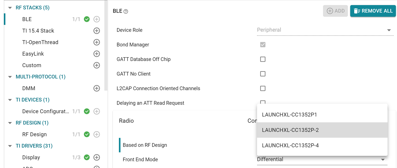
Figure 117. Select the correct option for “Based On RF Design” inside the RF Design and the stack modules of SysConfig [here an example for BLE]
The allowable TX power range with High PA enabled (programmmable by up to 6 dB) for the 2.4 GHz band is dependent on the RF design chosen. The LAUNCHXL-CC1352P-2 maximizes output from 14 to 20 dBm, whereas the LAUNCHXL-CC1352P-4 is optimized to support power levels from 6 to 10 dBm.
Note
There exist unexpected build or runtime behaviors caused by using the “Custom Board” SysConfig button in the 3.30 or 3.40 versions of the SimpleLink SDK. Please consult this E2E post for further instructions on how to resolve the issue.
Initial Board Bring Up
When powering up a custom board with the CC13xx or CC26xx for the first time, it is recommended to follow the Board Bring-Up section on CC13xx/CC26xx Hardware Configuration and PCB Design Considerations. After confirming that the board is being powered correctly by the battery or power supply and can be identified by the JTAG tool, programming the device with a minimal SW application to verify stability is also suggested.