Introduction to the SimpleLink Low Power F3 SDK
The SimpleLink Low Power F3 SDK delivers components that enable engineers to develop applications on the Texas Instruments SimpleLink CC23xx family of wireless microcontroller (MCUs). This powerful software toolkit provides a cohesive and consistent software experience for all SimpleLink CC23xx wireless MCU users by packaging essential software components, such as a Bluetooth® Low Energy (BLE) protocol stack supporting Bluetooth 5 and RF-Proprietary examples, the Free-RTOS kernel and TIDrivers in one easy-to-use software package along with example applications and exhaustive documentation.
Prerequisites
The user is expected to have the following:
CC23xx LaunchPad
A computer running a supported operating system listed in the Release Notes
This guide shows how to install and configure
TI CLANG Compiler
Code Composer Studio IDE
FreeRTOS - The SimpleLink Low Power F3 SDK does not deliver FreeRTOS sources. FreeRTOS can be downloaded here: FreeRTOS v202104.00 download link.
UniFlash
SmartRF Studio (optional)
Compiler Tools - Download and Installation
Download TI Arm Clang Compiler Tools.
Execute the installer. We recommend that you use the default installation folder.
IDE - Download and Installation
CCS Download and Installation
This section covers the required settings for a CCS installation. The CCS toolchain contains many features beyond the scope of this document. More information and documentation can be found on the Code Composer Studio tool page.
Check the SimpleLink Low Power F3 SDK release notes to see which CCS version to use and any required workarounds. Object code produced by CCS may differ in size and performance as compared to IAR produced object code.
Download CCS
CCS is available here: Code Composer Studio .
Refer to the SDK release notes for the version that is compatible with this SDK.
Installation Options
During the installation, the following options are recommended:
We recommend that you use the default installation folder
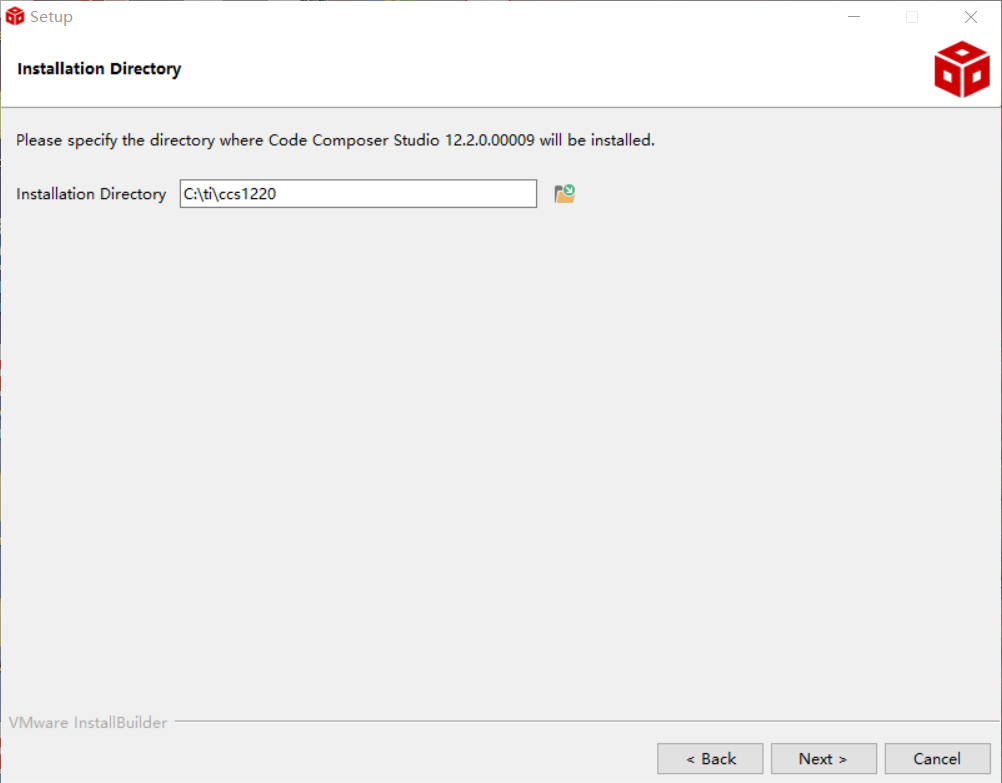
Figure 1. Default CCS Installation Location
You will then be prompted to select the device. Select “SimpleLink CC13xx, CC26xx and CC23xx Wireless MCUs”.
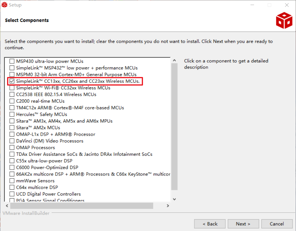
Figure 2. Select Processor Support
To use a debug probe, select TI XDS Debug Probe Support and any other options you would like. The CC23xx LaunchPad uses TI XDS Debug Probe by default.
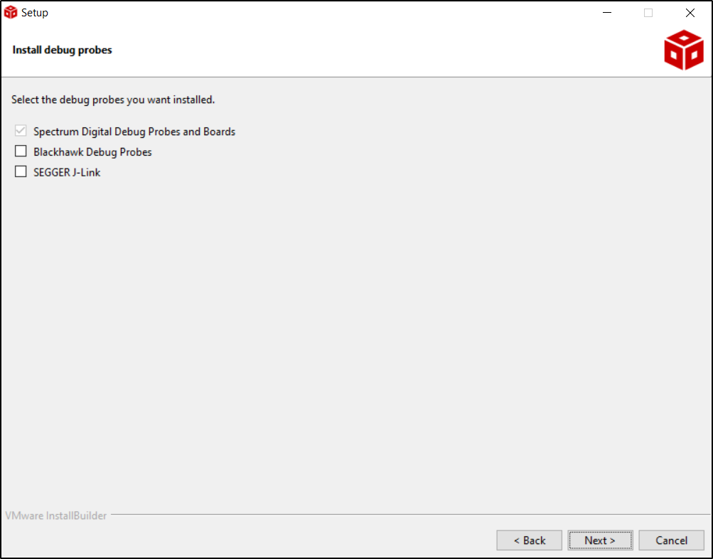
Figure 3. CCS Debugger Options
Discovering the SDK in CCS
If not already done, install the SDK in the default location pointed to by the installer -
c:/tiand restart CCS. CCS will automatically detect the latest install.Code Composer Studio automatically discovers the SimpleLink Low Power F3 SDK if it installed in its default installation directory (
c:/ti). Once discovered by CCS, it defines a build environment variable named COM_TI_SIMPLELINK_LOWPOWER_F3_SDK_INSTALL_DIR which is used by all SimpleLink Low Power F3 SDK projects.If a project is imported from a path other than what was specified during the SimpleLink Low Power F3 SDK installation, the COM_TI_SIMPLELINK_LOWPOWER_F3_SDK_INSTALL_DIR variable must be redefined after the import proceeding at a project-by-project basis. Project import is described later in this guide.
To redefine this variable:
Open the CCS project’s properties (Project → Properties)
Navigate to Resource → Linked Resources and edit COM_TI_SIMPLELINK_LOWPOWER_F3_SDK_INSTALL_DIR and have it point to your imported root directory location.
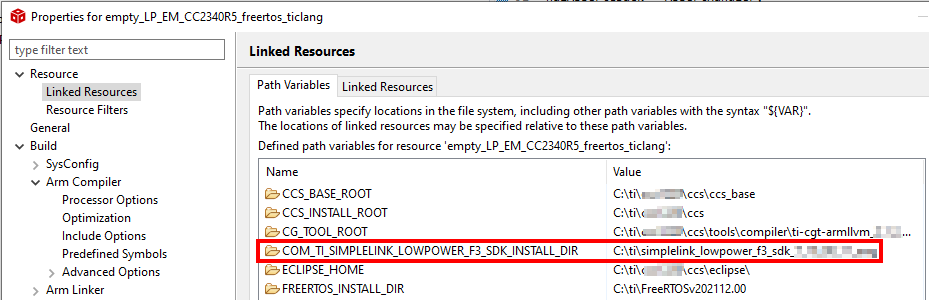
Figure 4. Redefining COM_TI_SIMPLELINK_LOWPOWER_F3_SDK_INSTALL_DIR
SDK - Download and Installation
The following steps have to be repeated for every new SDK.
Using the SDK Online
A quick and easy way to start working with the SDK is to use TI Resource Explorer on dev.ti.com. This online tool lets you explore the contents of the SimpleLink Low Power F3 SDK. You can build the examples directly using the cloud version of Code Composer Studio. If you choose to use the SDK online, there is no need to download the SDK to your local computer or install any tools (other than the TI Cloud Agent for first time users).
Installing the SDK
You can also download the SimpleLink Low Power F3 SDK from TI Resource Explorer or the software product page on TI’s website.
FreeRTOS - Download and Installation
Download FreeRTOS from FreeRTOS v202104.00 download link.
Unzip the file in
c:/ti.Set up CCS as described here.
Build your first program for the CC23xx device
Open CCS.
In CCS, click Project > Import CCS Projects.
When prompted, browse your files to locate the folder
<SDK>\examples\rtos\LP_EM_CC2340R5\drivers\empty.Select the project then click “Finish”.
The project will be imported and appear in the “Project Explorer”.

Build the project.
Set the project as the active project.
Select Project -> Build All to build the project.
As part of the prebuild process, SysConfig will run and generate code based on the
.syscfgin the workspace. For more information on SysConfig, see the SysConfig chapter of the User’s Guide.
Run your first program on the CC23xx device
Connect the CC2340Rx to the computer
This section provide a few options to connect your CC23xx device to a computer. This is required to download code on the device, run a debugging session, perform some power measurements, etc.
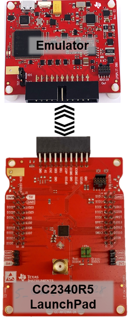
Option 1 - With a Modular LaunchPad™ Emulator
If you’re using one of the new TI Modular Launchpads™, you’ll need to connect the two sides of the Modular Launchpad™ together.
Option 2 - With a TI LaunchPad™
If you do not have access to a Modular LaunchPad™ Emulator, you can replace it by the upper part of a CC26x2R LaunchPad (or any TI Launchpad where a XDS110 debugger is available on the board).
Unplug the CC26x2R LaunchPad board
Remove all the jumpers from the CC26x2R LaunchPad board, except the one powering the XDS110.
Connect the required signals of the CC26x2R LaunchPad board with the signals of the CC23xx LaunchPad.
The signals are named differently on the CC26x2R LaunchPad board and on the CC23xx LaunchPad. Here how the signals should be connected.
CC26x2R LaunchPad board
CC23xx LaunchPad
GND
GND
5V
5V
3V3
3V3
RXD
RXD
TXD
TXD
RESET
nRST
TMS
SWDIO
TCK
SWDCK
TDO
Not Connected
TDI
Not Connected
SWO
Not Connected
Several alternatives are possible to achieve this
(Alternative 1) Use a 10-pin connector to connect the output of the XDS-110 to the XDS-110 input of the CC2340Rx Launchpad.
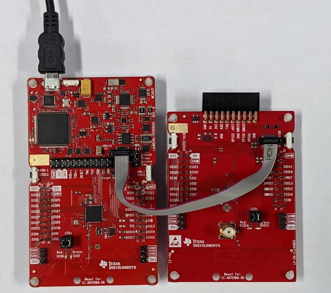
Figure 5. Connect the CC2340Rx LaunchPad using a 10-pin cable - The board on the left is a CC26x2R LaunchPad, the board on the right is the C2340Rx Launchpad.
Note
This does not connect the Tx and Rx UART signals to the debugger. These signals should be connected using a jumper wire. Usually, DIO22 is used for UART RX and DIO20 is used for TX.
(Alternative 2) Use a few jumper wires. The figure below shows the minimum required connections to perform software download. Additional connections will be required for reset and UART.
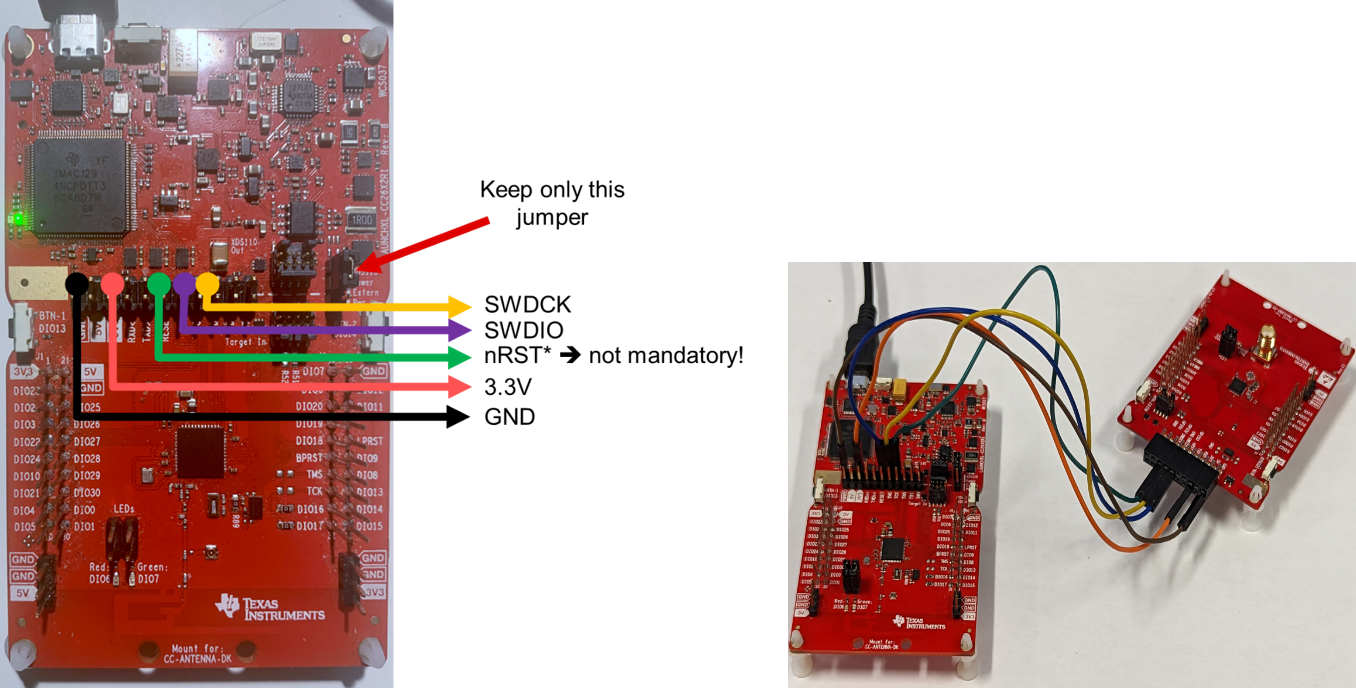
Figure 6. Connect the CC2340Rx LaunchPad using jumper wires - The board on the left is a CC26x2R LaunchPad, the board on the right is the C2340Rx LaunchPad.
Flash the device
Using CCS, download the project on the device using the Debug button.
Note
You may be prompted to update the XDS110 firmware – make sure to click “Update”.
Flash a pre-compiled image
Option 1 - Using UniFlash
This is the recommended approach. It requires to install an additional tool (UniFlash) but enables a more user-friendly interface.
Please refer to the procedure described in the next section.
Option 2 - Using CCS
As shown before, CCS can be used to build and flash images on the device. CCS can also be used to flash pre-built images.
Important
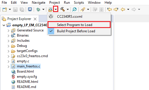
Make sure to import a CC2340R5 example - in other word to follow the previous sections - before attempting to flash a pre-compiled image. Otherwise, CCS will miss the debugging configuration files and may not let you download the image on the target.
Click on the small arrow next to the “Flash” icon.
Browse to find the .out or .hex file you want
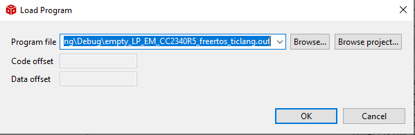
Click “OK”.
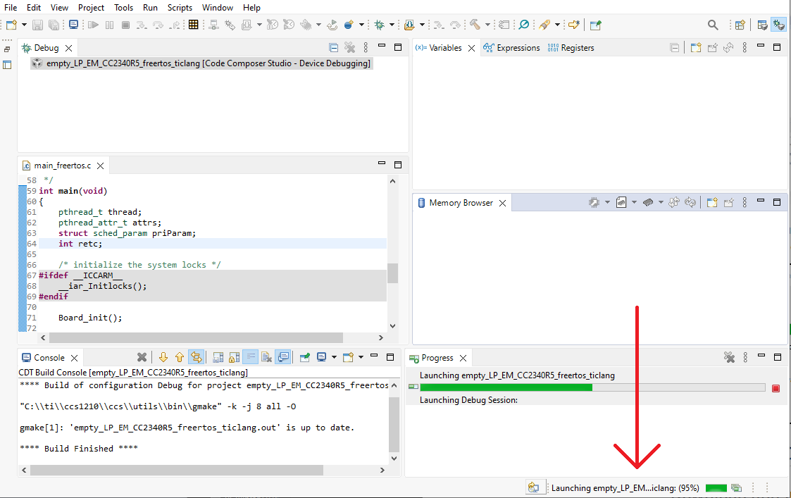
A few operations should occur in background. The progression of these can be seen at the bottom right of the CCS window.
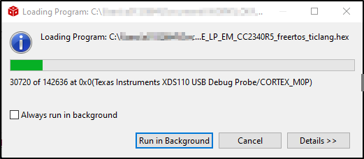
After that, you should get a window showing the progress of the download. No action is required, the download will occur automatically.
UniFlash for CC23xx
Download and Installation
Download Uniflash version 8.2.0 or newer
Execute the installer to install UniFlash in the default location (
c:/ti).
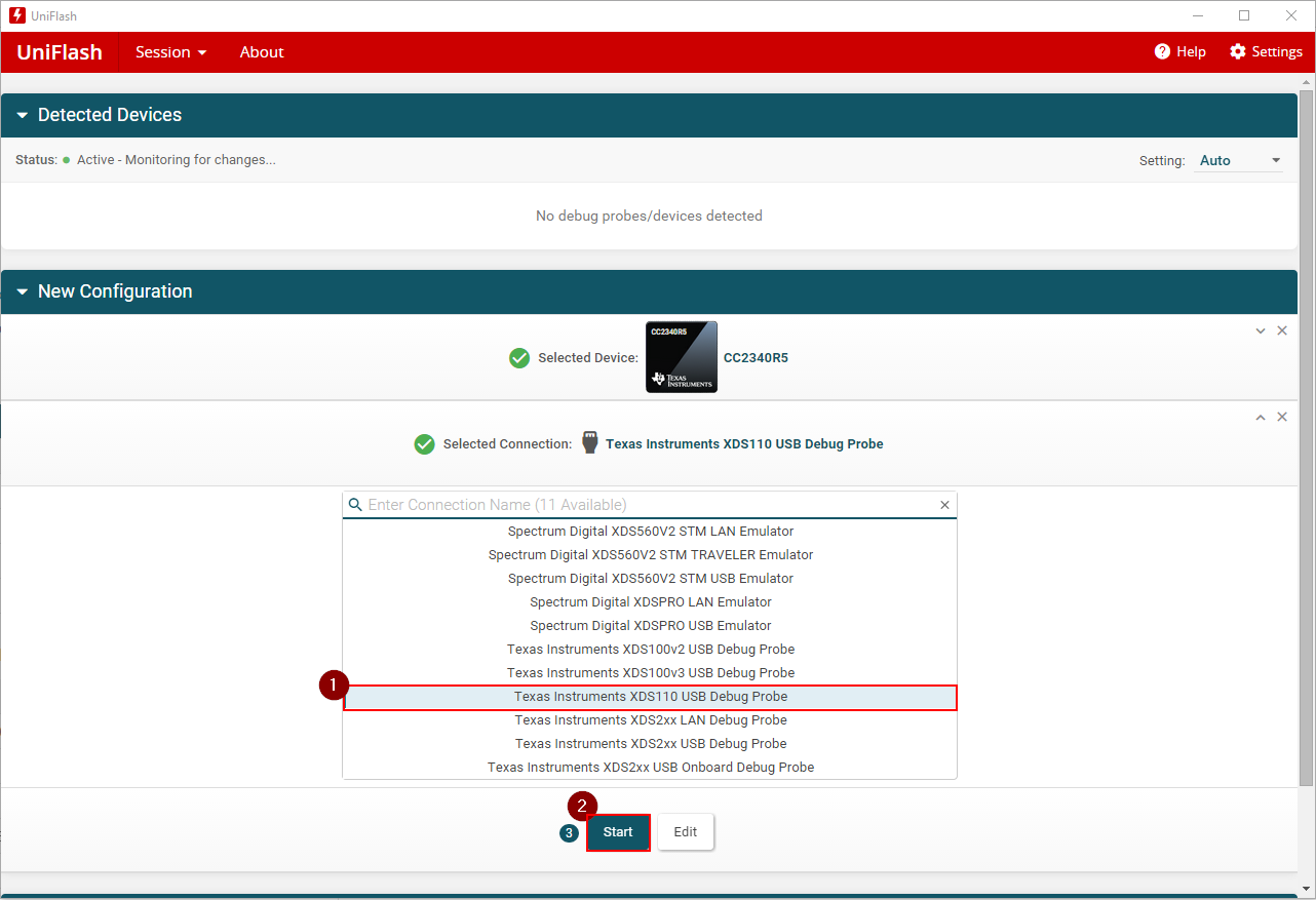
Usage
Select the device you are working with.
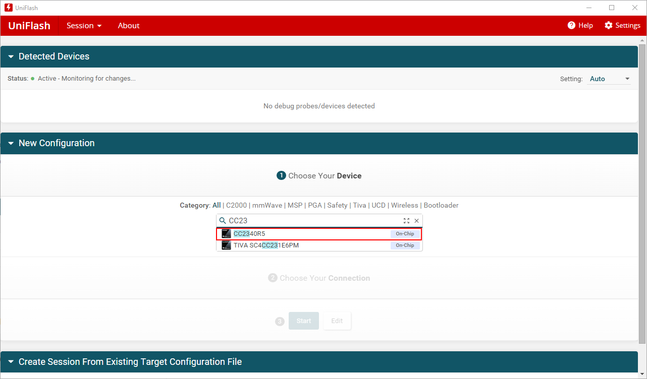
Select the debugger used and click on “Start”
SmartRF Studio for CC23xx
SmartRF Studio helps running RF tests on the CC23xx.
Download and Installation
Download SmartRF Studio 8 with support for CC23xx from the software product page on TI’s website.
Execute this file to install SmartRF Studio 8.
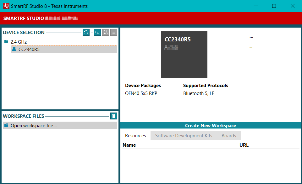
Device Connection
Start SmartRF Studio 8. Below screenshot shows the UI without hardware connected.
Connect the CC23xx LaunchPad to the computer via the LP-XDS110 or LP-XDS110ET using the provided USB cable as described in Connect the CC2340Rx to the computer.
Click on the
 button next to
 DEVICE SELECTIONand the debug probe will be listed as shown below: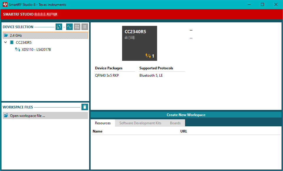
Double-click on
 to open the Radio Control Window.
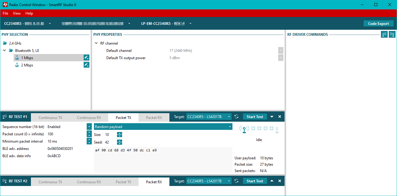
RF Settings
Two default PHY settings are provided: 1 Mbps and 2 Mbps. Both at channel 17
(2440 MHz) and with an output power of 5 dBm. To change this settings, press the
 button to the right of the one to be copied to Create new
custom PHY based on this PHY. Changing the channel and output power is now
possible as shown in Figure 7.
button to the right of the one to be copied to Create new
custom PHY based on this PHY. Changing the channel and output power is now
possible as shown in Figure 7.
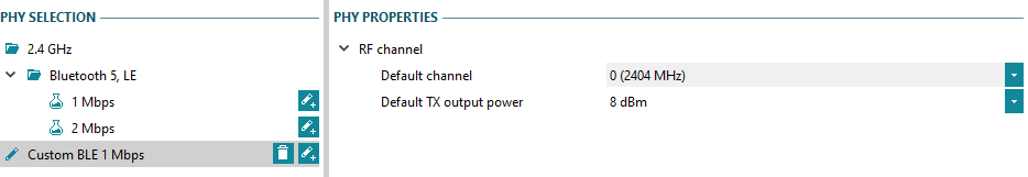
Figure 7. Creation of custom BLE PHY.
Continuous TX/RX
SmartRF Studio 8 can transmit a continous wave on a frequency and output power
selected in the RF Settings. Select the tab
Continuous TX as shown in Figure 8.
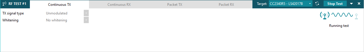
Figure 8. Transmission of a continous wave.
The tab Continuous RX enables the reception of signals on a frequency
selected in the RF settings, see Figure 9.
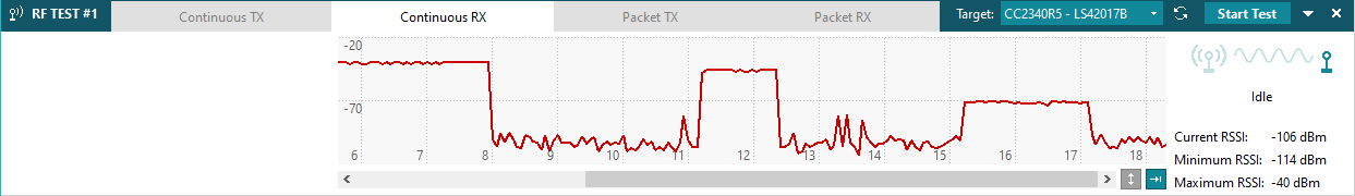
Figure 9. Receiving signals from another CC23xx LaunchPad.
BLE Packet TX/RX
BLE packets can be transmitted in the Packet TX tab within RF TEST #1
(see Figure 10.). This will transmit
non-connectable packets. The payload data can be changed in the UI.
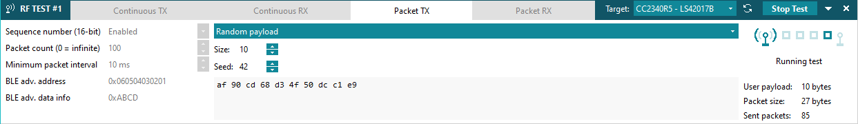
Figure 10. SmartRF Studio 8 in TX mode transmitting BLE packets.
BLE packet can be received in the tab Packet RX (see
Figure 11.).
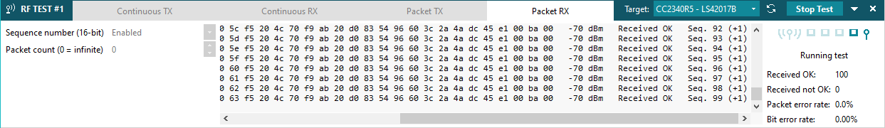
Figure 11. SmartRF Studio 8 in RX mode receiving BLE packets.