

|
|
I2S driver implementation for LPF3 devices.
============================================================================
Only the following memory lengths are supported:
Some attributes in the I2S_Params structure have a limited set of supported values. These limitations are described below:
This section describes the structure and requirements for the sample buffers used in the I2S_Transaction objects.
Sample words are read from or written to the sample buffers in little-endian byte order, meaning that the least significant byte (LSByte) is stored at the lower byte address, and the most significant byte (MSByte) is stored at the higher byte address.
The sample buffers are divided into frames which are further subdivided into channels, and if a channel is used by both SD0 and SD1 (where the direction of the two pins are the same), then that channel is further subdivided into a sample word for first SD0 and then SD1.
The size of the buffers used in I2S_Transaction objects must be an even multiple of the number of bytes per frame. I.e. the number of bytes in the buffers must be of the form: 2*n*k, where k is the size of a frame in bytes and n is an integer satisfying n>=2. 2*n is the number of frames in the buffer.
Below code describes the general structure of a sample buffer if SD0 and SD1 are configured to the same direction.
Notes:
SD0_USE_CHANNEL_n should be true if SD0 uses channel n, otherwise false.SD1_USE_CHANNEL_n should be true if SD1 uses channel n, otherwise false.BYTES_PER_WORD is based on the configured memory length:
FRAMES_PER_BUFFER must be divisible by 2sampleBufferFrames needs to be cast to an uint8_t pointer to be used with the I2S driver.If SD0 and SD1 are not configured to the same direction (or only one is used) then the structure can be simplified as below:
Notes:
USE_CHANNEL_n should be true if channel n is used, otherwise false.If for example SD0 and SD1 are configured to the same direction and if channel 0 and 1 are used for SD0 and channel 0 is used for SD1, then the sample buffer would be structured as in the code below.
Using I2SLPF3_HWAttrs.afclkSrc it is possible to select the audio frequency clock (AFCLK) source. AFCLK is used by the I2S hardware module when the I2S driver is opened in Controller mode (I2S_Params.moduleRole == I2S_CONTROLLER) The I2S hardware module will divide the AFCLK to generate the I2S clocks (BCLK (SCK), WCLK (Ws) and CCLK). The AFCLK therefore directly determines the possible sample rates, i.e. the frequency of WCLK.
To achieve a desired sample frequency (f_s), the following requirements must be met, where f_afclk is the frequency of the AFCLK:
For example, if f_s = 44.1 kHz, then the first requirement is met if for example f_afclk = 90.3168 MHz = 2048 * 44.1 kHz. The second requirement is met if for example the number of bits per frame is 32, because it evenly divides into 2048.
If the requirements are not met, the closest possible sampling frequency to the desired sampling frequency will be used.
To achieve the most common sample frequencies, it is suggested to select AFOSC as the AFCLK source, since its frequency can be configured to be a multiple of the most common sample rates.
See PowerLPF3_AfoscFreq for the list of possible frequencies that the AFOSC can be configured to. The frequencies most suited to be used with I2S are listed below:
#include <stdint.h>#include <stdbool.h>#include <ti/drivers/I2S.h>#include <ti/drivers/dpl/SemaphoreP.h>#include <ti/drivers/dpl/HwiP.h>#include <ti/drivers/Power.h>#include <ti/devices/DeviceFamily.h>#include <DeviceFamily_constructPath(inc/hw_ckmd.h)>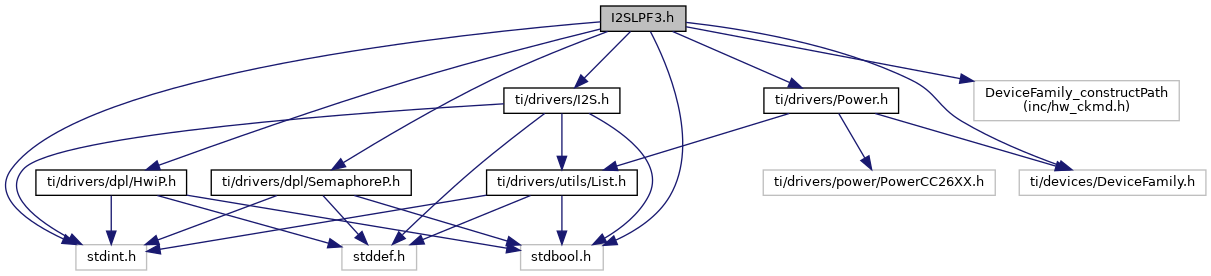
Go to the source code of this file.
Data Structures | |
| struct | I2SLPF3_HWAttrs |
| I2S Hardware attributes. More... | |
Enumerations | |
| enum | I2SLPF3_AfclkSrc { I2SLPF3_AFCLK_SRC_CLKREF = CKMD_AFCLKSEL_SRC_CLKREF, I2SLPF3_AFCLK_SRC_CLKHF = CKMD_AFCLKSEL_SRC_CLKHF, I2SLPF3_AFCLK_SRC_CLKAF = CKMD_AFCLKSEL_SRC_CLKAF } |
| Audio Frequency Clock Source. More... | |
| enum I2SLPF3_AfclkSrc |