Introduction
Note
Please note that this lab only applies to SDK 3.30.00. We are in the process of revamping our RTLS SimpleLink Academy Lab content and plan to release an update for SDK 3.40.00.
For updated documentation RTLS for SDK 3.40.00 please refer to the TI BLE-Stack User's Guide.
Please also note that the RTLS Agent has moved and is now found in the
<SIMPLELINK_CC2640R2_SDK_INSTALL_DIR>\tools\blestack\rtls_agent folder. For
more info, see the RTLS example project readme files.
This module is an introduction to the Real Time Localization System (RTLS) Toolbox as well as its suite of PC tools. The RTLS toolbox is a collection of tools for localization, direction finding, and secure range bounding.
The RTLS architecture consists of software running on the host (PC) and the embedded device (CC26xx). Embedded RTLS nodes are controlled by the host via commands over UART. Host software is responsible for sending commands to the embedded nodes and collecting the results. The suite of host software is referred to as the RTLS Node Manager.
It is assumed that the reader has a basic knowledge of embedded tool chains and general C and Python programming concepts.
This lab is based on the rtls_master rtls_slave and rtls_passive projects
that are part of the
SimpleLink™ CC2640R2 SDK.
This lab will focus on running the out of box demos, setting up the host Python environment, and getting started with data collection using Angle of Arrival (AoA) or Time of Flight (ToF).
Prerequisites
Software for desktop development
- SimpleLink™ CC2640R2 SDK 3.30
- Those listed under the Dependencies section of the CC2640R2 SDK Release Notes
- Python 3.7 or higher
- Git bash
- RTLS known issues page on E2E. Apply all relevant fixes from this page.
- Chrome web browser
Hardware
This module requires the following kits:
- 3x CC2640R2-LAUNCHXL
- 1x BOOSTXL-AoA
Recommended reading
These chapters in the TI BLE-Stack User's Guide
- Getting Started
- The CC2640R2F SDK Platform
- Application
- BLE-Stack
- RTLS Toolbox
- Network Processor Interface (NPI)
Getting started with AoA booster pack
Project readme files:
- rtls_master
- All relevant information to
rtls_slaveandrtls_passiveis contained in thertls_masterreadme rtls_agentReadme located in <SimpleLink CC2640R2 SDK> → tools → blestack → rtls_agent folder within the CC2640R2 SDK. This will be covered in detail in Task 2.
Getting started – Desktop
Install the Software
- Run the SimpleLink CC2640R2 SDK installer.
- Install Python 3.7 or later from the Python Download page.
- Setup the Python environment as described in the README.html in the <SimpleLink CC2640R2 SDK> → tools → blestack → rtls_agent folder.
- If a bash environment doesn't exist on your system, install Git bash
This gives you:
- The SDK with TI-RTOS included at
<SIMPLELINK_CC2640R2_SDK_INSTALL_DIR>which defaults toC:\ti\simplelink_cc2640r2_sdk_x_xx_xx_xx. - Python 3.7 environment with all dependencies required by the RTLS Node Manager
Modify/Load the software
- Load Board #1 + BOOSTXL-AoA with
rtls_passiveproject:
<SimpleLink CC2640R2 SDK> → examples → rtos → CC2640R2_LAUNCHXL → blestack → rtls_passive - Load Board #2 with
rtls_slaveproject:
<SimpleLink CC2640R2 SDK> → examples → rtos → CC2640R2_LAUNCHXL → blestack → rtls_slave - Load Board #3 with
rtls_masterproject:
<SimpleLink CC2640R2 SDK> → examples → rtos → CC2640R2_LAUNCHXL → blestack → rtls_master
Building the projects
Be sure to build both the stack and application before loading projects.
Note that the rtls_passive uses the micro BLE-Stack setup as a connection
monitor, therefore it does not have a separate stack project.
The following tasks will show you how to get started with data collection using the RTLS toolbox. This lab will focus on the RTLS Toolbox as a whole and the Python based PC environment. Subsequent labs will cover AoA or ToF specific topics.
Localization Techniques
A Real Time Localization System can be defined as a system capable of determining the position of a target within a defined physical area in real time. The physical area is normally defined through deployment of reference/locator nodes.
There are two fundamentally different approaches to location finding:
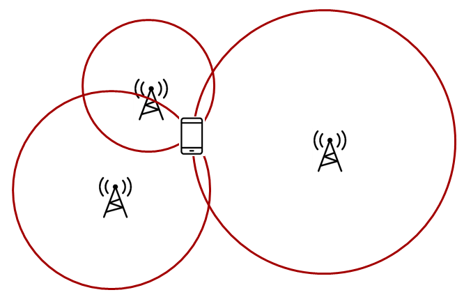
Trilateration, where you know the distance between a reference node and a
target node. Time of Flight gives you the distance from the receiver to the transmitter.
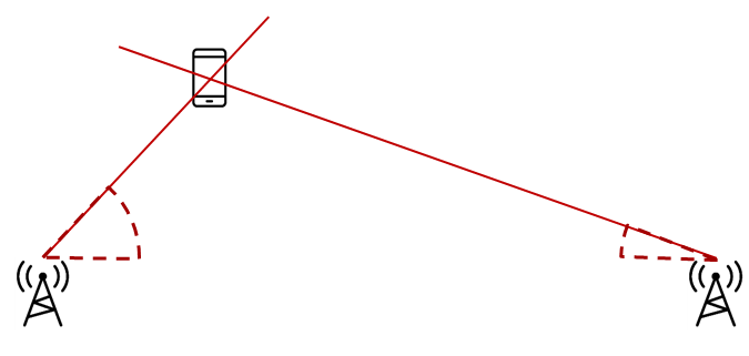
Triangulation, where you know the direction from a reference node to a target
node. Angle of Arrival is a technique that can be used to measure the angle
from the receiver to the transmitter.
What is a node?
A node in this case is referred to as a localization capable embedded device. For the demos in the SDK, nodes are LaunchPads
RTLS Toolbox Introduction
In the Localization Techniques, we discussed how multiple AoA nodes can combine angle information to perform triangulation and how multiple ToF nodes can combine distance information to perform trilateration. It is important to remember in the pictures above, it is not possible for one single node to localize an object using the TI sample applications. A single AoA node only produces one angle, and a single ToF node only produces one distance. These by nature, are ambiguous measurements. If there are at least two nodes providing AoA or ToF data, then localization can occur. This requires a fourth device that is capable of combining the samples from the individual nodes and finding the intersection.
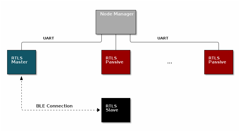
The intersection between the angles (AoA) or circles (ToF) is the estimated location of the device. An overview of the topology is shown below. In the diagram below, the black, blue, and red boxes represent CC2640R2 LaunchPads while the grey box is a PC.
Time of Flight performs which of the following localization techniques?
For a comprehensive presentation of the RTLS toolbox and its software components, please see the TI BLE-Stack User's Guide
RTLS Roles and Topology
Each node in an RTLS network utilizes the software components listed above
in a different role to perform a specific task related to localization. There are
three examples: rtls_master, rtls_slave, and rtls_passive. The capabilities
of these examples are explained below.
RTLS Master
The RTLS master runs a full BLE-Stack and acts as a BLE central device. It will scan and connect to the RTLS slave over BLE. Once a connection is established the RTLS Master will do the following:
- Share the connection parameters (access address, master sleep clock accuracy, and CRC init) with the PC.
- Use the BLE link to share ToF and AoA parameters with the peripheral device.
- Implements the ToF master role
- The RTLS master does not send out AoA packets, but configures the slave to do so.
RTLS Slave
The RTLS slave runs a full BLE-Stack and acts as a BLE peripheral device. This is the device that is to be located. The slave device will advertise and enter a connection with the RTLS Master.
- Advertises special string to be detected by
rtls_master(covered in detail in Task 3) - BLE-Stack peripheral role
- Implements ToF slave role
- Sends data packets with AoA tone embedded using Constant Tone Extension (CTE). More information on CTE can be found in the Bluetooth 5.1 Core Spec
- Wireless/battery operated, not connected to PC
RTLS Passive
The RTLS passive does not actively participate in the BLE connection between the RTLS master and slave. Instead, it uses the Micro BLE-Stack in connection monitoring mode to follow the connection. To do this, the passive device relies on the Master to distribute the connection parameters once a connection is formed. The passive node does the following:
- Implement ToF passive role
- Receives packets with CTE and performs in-phase and quadrature component (IQ) sampling
- Uses Micro BLE-Stack in Connection Monitoring mode to follow connection between master and slave
Note: For SDK 3.30 and later, the RTLS passive can be used but is not necessary for ToF. The passive is still required for AoA. More details will be provided in the labs.
PC/Central Processing Node
The PC node is responsible for controlling the embedded RTLS nodes by sending commands and processing events. In the SDK, this is realized by a combination of a Python layer that implements the UNPI master role and a rtls_agent_cli server that translates UNPI commands to a socket interface that is used by the GUI Composer application running in the browser. In a final product, these algorithms may be implemented on an embedded device or even perhaps the RTLS master node.
The PC implements the following roles in Python:
- UNPI master
- COM port interface
- Implementation of RTLS UNPI subsystem/command set
- rtls_agent_cli server
The PC implements the following roles in GUI Composer/Javascript:
- rtls_agent_cli client on localhost
- Graphing and logging data from rtls_agent_cli
- Parsing JSON objects to extract RTLS data
- Issue commands to RTLS nodes via rtls_agent_cli to UNPI conversion
- Enumerate devices
- Distribute connection parameters to passive nodes
Quiz!
Is it possible to have multiple RTLS passive devices in a network?
Why would multiple passive devices be desirable? (select all that apply)
Task 1 – Running the RTLS Demo
In this task, we will use the pre-compiled rtls_agent_cli.exe located at
<SimpleLink CC2640R2 SDK> → tools → blestack → rtls_agent → rtls_monitor.
It is recommended to familiarize yourself with the readme in the parent folder
before starting.
Apply any fixes from the RTLS known issues page on E2E
See the image below for a recommended layout of the nodes during evaluation, this is a 2D image where all devices are laying on a flat surface "pointing" as shown in the picture. In this case each node should be placed on a box so that it does not sit directly on the ground. Note that a desk environment generally has sub-optimal RF conditions and should be avoided. Take note that the below image shows the
rtls_passivein AoA configuration. By default the SDK will configurertls_passiveas for ToF, see the bonus below for more info. Note the BOOSTXL-AOA should not be used for ToF.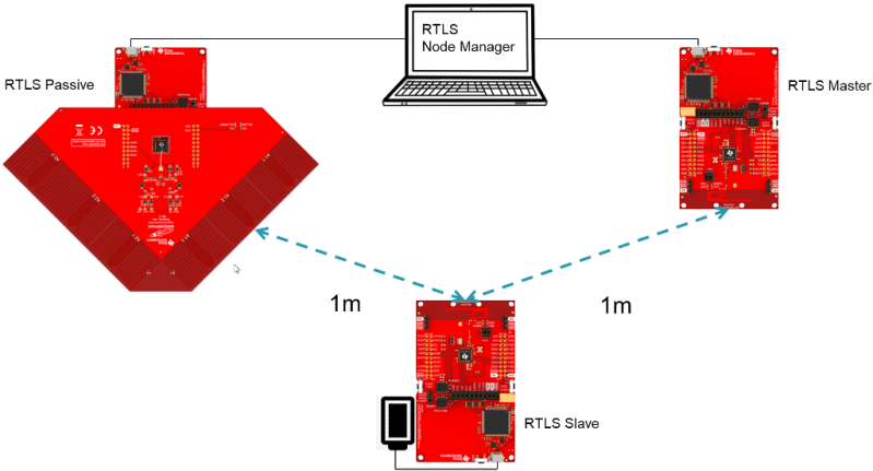
Build the projects and flash the LaunchPads as described in Modify/Load the software
Run the pre-compiled
rtls_agent_cli.exe, press 'a' to auto detect the LaunchPads connected to your PC. This will trigger thertls_agent_cli.exeto sendRTLS_CMD_IDENTIFYto each node.- Two ports (
RTLS_MASTERandRTLS_PASSIVE) should successfully identify (show OK in the left column) - Note that it is normal to receive NoRsp from ports if they are not programmed with
RTLS_MASTERorRTLS_PASSIVEsoftware. Additionally, the COM ports used by the JTAG debugger will not respond, so NoRsp is expected there as well. - Once the nodes are identified, press enter to start the agent. The right pane will now show "Waiting for data..."
- Two ports (
Navigate to TI GUI Composer Gallery and search for "RTLS Monitor" Use version
0.9.5.- Select the RTLS_Monitor and click on it, this will open it in the browser view of GUI composer. (We recommend using the latest version of Chrome.)
- Note that each version of RTLS Monitor corresponds to a specific version of the SDK.
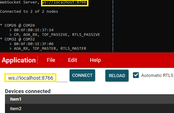
At the time of writing
0.9.5is latest and corresponds to theCC2640R2 SDK 3.30The WebSocket server address in the terminal and the GUI should match as such:
Click the connect button, this will connect to the rtls_agent_cli running on localhost.
What to do if default port is in use already?
If after you click the connect button the RTLS_Monitor, you see Closed as part of the logging msg as shown below.
Then you can change the port by following the steps below: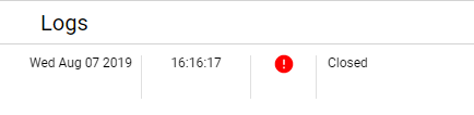
Close the rtls_agent_cli.exe
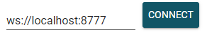
Type
winpty ./rtls_agent_cli.exe -p 8777in git bash to change the port number to 8777 or anyother number you would like.Change the port number used in RTLS_Monitor to the one you choose. For example:
On success, you should be able to see graph window displaying sample data.
- It will take ~30 seconds before the graph starts showing data.
- We will cover more about what is happening during that time and what it takes to setup a RTLS network in Task 3.
- If evaluating in ToF mode, you should not move the nodes until the GUI starts receiving data, because ToF is calibrating. Once the GUI starts graphing, it is okay to move the nodes around. The default calibration distance is 1m.
Automatic RTLS
If the "Automatic RTLS" checkbox is enabled then the GUI will connect to the first RTLS slave device it finds and will immediately start AoA or ToF. When this box is unchecked it is possible to scan and select the slave device manually via Bluetooth Address listed in the "Remote devices" combobox.
This is helpful if there are multiple RTLS slaves in the area.
Bonus
Define RTLS_LOCATIONING_AOA in all three example projects. (For rtls_master
and rtls_slave, it is found in build_config.opt. For rtls_passive, define
it in the preprocessor defines in the project properties.) Repeat the steps above.
What changed?
Quiz!
What localization technique does the out of the box software employ?
Review the log, what devices are providing ToF distance measurements?
What is the format of the individual logs being sent between the rtls_agent_cli server and GUI Composer?
Assessing RTLS performance using the out of the box demos
The RTLS demos provided by TI are intended for evaluation use only and serve as a starting point for localization development. Better performance and accuracy can be achieved by utilizing the foundational demo toolkit provided by TI and developing advanced, customized algorithms to process AoA and ToF data. See the AoA and ToF specific labs for detailed information on demo results that can be used as a performance baseline as well as tips on improving performance.
The demo you have run is not optimized for performance. It instead serves as a starting point for localization development. It is possible to achieve much better performance and accuracy than is seen here by developing advanced algorithms to process AoA and ToF data. TI is actively looking into algorithm development and encourages their customers to do so too. This is a strong way of differentiating a localization product. See the AoA and ToF specific labs for more discussion and explanation of the results
Task 2 – Use RTLS Node Manager Directly
This task will bypass the GUI Composer application and interact directly with
the RTLS Python APIs to collect data. This gives power to the developer to define
custom behavior of the RTLS network and control the devices directly.
Specifically, this will cover setting up the required Python dependencies and
running the rtls_example_with_rtls_util.py template script described in the SDK.
Assumptions and Notation
Before starting this task the following is assumed
- A command prompt supporting bash or Git bash is open and running.
- Unix style slashes will be used throughout. If it is necessary to run these
steps in the Windows Command Prompt (
cmd.exe), then/should be replaced with\. - Various command prompts will search your System Path variable to find Python. If you have a pre-existing Python version in your path this may be selected over the newly installed version. To prevent mixing the two up, we will use virtual environments.
- We assume that Mac users don't have another instance of Python 3 installed.
If this is not the case, then based on the
PATHvariable an older version of Python may be selected with invoking thepython3command. Be sure to invoke the correct version of Python. - Here we re-hash some of the instructions from the rtls_agent/readme.html. Some steps may be redundant if you already followed this and have the python environment setup.
- Install Python per steps in Getting started
- Open a command prompt (Git Bash is recommended)
Create a Python virtual environment
- Navigate to the SDK folder (e.g.
C:\ti\simplelink_cc2640r2_sdk_x_xx_xx_xx\tools\blestack\rtls_agent) - Execute
py -3.7 -m venv .venv(windows) orpython3 -m venv .venv(mac). - This will create a folder called
.venvin the current directory that includes a copy of the python interpreter and a sandbox for installing packages. - Activate virtual environment using
source .venv/Scripts/activate(bash) or.venv\Scripts\activate.bat(Windows cmd) - Observe that when a venv is activated
(.venv)will appear before each cmd prompt - Notice that once the virtual environment is activated, the
pythoncommand will use the local Python interpreter in the venv. See Virtual Environments for more info.
- Navigate to the SDK folder (e.g.
Install RTLS packages
This step will use package.bat (for Windows) or package.sh (for Linux / Mac) to install the RTLS packages.
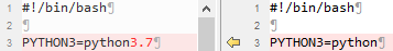
Workaround to deal with hard-coding in package install scripts
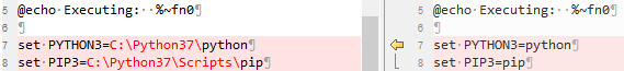
Unfortunately the package install script hard-codes the python 3 location. This does not work if you have created a virtual environment as per the previous step. To fix this:
- In Windows, make the following change (code on right is fixed version):
- In Linux/Mac, make the following change (code on right is fixed version):
- In Windows, run
winpty ./package.bat -c -b -u -ior in Linux / Mac runpackage.sh -c -b -u -i
- In Windows, make the following change (code on right is fixed version):
Install required external Python Dependencies into the newly created virtual environment
- Execute
python -m pip --proxy www.proxy.com install -r requirements.txt - Note that above
--proxy www.proxy.comis only required if behind a proxy. www.proxy.comis an example of a proxy. It should be replaced with the web address of your specific proxy if applicable.- This will install the required external Python packages that are needed by the RTLS
Python suite (these are listed in
requirements.txt).
- Execute
Open the
examples/rtls_example_with_rtls_util.py, go to line 66, and edit the linesdevices = [ {"com_port": "COM37", "baud_rate": 460800, "name": "CC26x2 Master"}, {"com_port": "COM29", "baud_rate": 460800, "name": "CC26x2 Passive"},to use the COM ports of the master and passive LaunchPads.
Note
The "name" field above does not affect the functionality. It is simply used for logging purposes and therefore it is not required to modify this if not desired.
Save the file and run it using
python -u examples/rtls_example_with_rtls_util.py.- The script will scan for RTLS devices, connect, and then print continuous connection information (RSSI, channel) for 5 seconds.
- See below for sample output snippet (note that the addresses and COM ports will be different).
- The out-of-box demo only reports continuous connection information (CCI). The following sections will describe this mode as well as all other possible modes (AoA, ToF, etc) in more detail.
Master : <RTLSNode(CC26x2 Master, started 9420)>
Passives : [<RTLSNode(CC26x2 Passive, started 23280)>]
All : [<RTLSNode(CC26x2 Passive, started 23280)>, <RTLSNode(CC26x2 Master, started 9420)>]
Devices Reset
Start scan for 15 sec
Scan Results: [{'addr': '54:6C:0E:83:36:B5', 'addrType': 0}]
Connection Success
CCI Callback Set
CCI Started
Going to sleep for 5 sec
[10:18:2019 16:48:41:535250] : {"name": "CC26x2 Master", "type": "conn_info", "identifier": "54:6C:0E:83:35:31", "payload": {"rssi": -42, "channel": 12}}
[10:18:2019 16:48:41:568250] : {"name": "CC26x2 Passive", "type": "conn_info", "identifier": "54:6C:0E:83:31:84", "payload": {"rssi": -39, "channel": 25}}
[10:18:2019 16:48:41:635251] : {"name": "CC26x2 Master", "type": "conn_info", "identifier": "54:6C:0E:83:35:31", "payload": {"rssi": -51, "channel": 25}}
[10:18:2019 16:48:41:669251] : {"name": "CC26x2 Passive", "type": "conn_info", "identifier": "54:6C:0E:83:31:84", "payload": {"rssi": -43, "channel": 1}}
[10:18:2019 16:48:41:736569] : {"name": "CC26x2 Master", "type": "conn_info", "identifier": "54:6C:0E:83:35:31", "payload": {"rssi": -42, "channel": 1}}
[10:18:2019 16:48:41:770616] : {"name": "CC26x2 Passive", "type": "conn_info", "identifier": "54:6C:0E:83:31:84", "payload": {"rssi": -38, "channel": 14}}
[10:18:2019 16:48:41:838030] : {"name": "CC26x2 Master", "type": "conn_info", "identifier": "54:6C:0E:83:35:31", "payload": {"rssi": -43, "channel": 14}}
[10:18:2019 16:48:41:876064] : {"name": "CC26x2 Passive", "type": "conn_info", "identifier": "54:6C:0E:83:31:84", "payload": {"rssi": -40, "channel": 27}}
[10:18:2019 16:48:41:940744] : {"name": "CC26x2 Master", "type": "conn_info", "identifier": "54:6C:0E:83:35:31", "payload": {"rssi": -53, "channel": 27}}
[10:18:2019 16:48:41:980798] : {"name": "CC26x2 Passive", "type": "conn_info", "identifier": "54:6C:0E:83:31:84", "payload": {"rssi": -43, "channel": 3}}

...

[10:18:2019 16:48:46:254596] : {"name": "CC26x2 Passive", "type": "conn_info", "identifier": "54:6C:0E:83:31:84", "payload": {"rssi": -43, "channel": 7}}
[10:18:2019 16:48:46:259877] : {"name": "CC26x2 Master", "type": "conn_info", "identifier": "54:6C:0E:83:35:31", "payload": {"rssi": -51, "channel": 31}}
[10:18:2019 16:48:46:357360] : {"name": "CC26x2 Passive", "type": "conn_info", "identifier": "54:6C:0E:83:31:84", "payload": {"rssi": -38, "channel": 20}}
[10:18:2019 16:48:46:361386] : {"name": "CC26x2 Master", "type": "conn_info", "identifier": "54:6C:0E:83:35:31", "payload": {"rssi": -42, "channel": 7}}
[10:18:2019 16:48:46:457799] : {"name": "CC26x2 Passive", "type": "conn_info", "identifier": "54:6C:0E:83:31:84", "payload": {"rssi": -42, "channel": 33}}
[10:18:2019 16:48:46:463803] : {"name": "CC26x2 Master", "type": "conn_info", "identifier": "54:6C:0E:83:35:31", "payload": {"rssi": -46, "channel": 20}}
Try to stop CCI result parsing threadSTOP Command Received
CCI Stopped
Master Disconnected
Done
Why is it recommended to create a virtual Python environment (select all that apply)?
Task 3 – Building Custom RTLS Python Scripts
With the environment setup, it is time for us to use Python directly to control the RTLS nodes. The goal of this task is to explain the RTLS PC software and to walk through setting up a RTLS network.
You might want to revision or make a copy of the default rtls_example_with_rtls_util.py so it is
preserved. Save it with another name like rtls_example_old.py as a backup.
RTLS Node Manager Python Overview
First, we will briefly discuss the important layers of the Python solution and their role.
/rtls_agent
    /examples/
      rtls_example_with_rtls_util.py - Example to exercise rtls_util functionality

    /rtls_util/
      rtls_util.py -  Main interface for examples. Class that abstracts
                      RTLSManager and RTLSNode functionality. Handles waiting
                      for RTLS responses in order to provide synchronous API's.
                      Stores asynchronous data into queues for use by a consumer.
                      Raises any unexpected functionality as an exception.

    /rtls/
        /rtls/
            rtlsmanager.py - Class to manage multiple nodes in an RTLS network.
                             Subscribes to incoming data from the nodes, routes
                             outgoing data to each of the nodes. Distributes
                             connection parameters from master node to any
                             connected passive nodes when an connection is
                             established. Handles messages from rtls_agent_cli server
                             if one is provided.

            rtlsnode.py -    Class that implements the basic functionality of a node
                             in an RTLS network. This class will query the embedded
                             device connected to it and determine its capabilities.
                             Essentially this assigns a role in an RTLS context to
                             a COM port.

            ss_rtls.py       Defines the commands in the RTLS UNPI subsystem.
                             This file will define builder classes for the various
                             UNPI commands that the RTLS subsystem supports.

      /unpi/
          serialnode.py - Thread that manages serial communication from COM ports.
                          to higher layers.
                          Queues up messages and sends them to parser.
          unpiparser.py - Parser for Unified Network Processor Interface messages.
                          Implements UNPI frame format packing/unpacking.
RtlsUtil Summary
It is recommended to build RTLS based Python applications on top of the
RtlsUtil class within rtls_util.py. This class forms the RTLS API set. A call
to an RtlsUtil method translates to a sequence of one or more RTLS UNPI commands
/ responses from ss_rtls.py. In this way, RtlsUtil is an abstraction of both the
RTLS UNPI communication as well as the RTLSManager which manages the various
RTLSNode's.
Any errors in an RtlsUtil method will be reported as an exception raised to the
RtlsUtil consumer (i.e. rtls_example_with_rtls_util.py). Alternatively, if the
method returns, the functionality has been performed successfully.
Asynchronous localization data is received and stored into one of the following queues depending on the data:
- RtlsUtil.aoa_results_queue
- RtlsUtil.tof_results_queue
- RtlsUtil.conn_info_queue
RTLS Python Program Template
The rtls_example_with_rtls_util.py from the previous task
shows how to perform basic initialization of RtlsUtil as well
as setting up the networking and collecting localization data.
Here we highlight some of the important parts of the example:
The beginning of main() has several boolean variables to enable / disable
example functionality. It is possible to combine any of these modes together.
Each variable will be explained in a section below or their own lab.
cci: Continuous Connection Informationaoa: Angle of Arrivaltof: Time of Flightupdate_conn_interval: Updating Connection Interval
Out-of-box Functionality
The out-of-box functionality, as demonstrated above, only has continous connection information enabled.
Common Initialization
There is initialization functionality that is common to all modes. First, construct an instance of the RTLSUtil class to serve as the RTLS Node Manager interface. The first parameter is the file to log debug information to and the second parameter is the logging level.
rtlsUtil = RtlsUtil(logging_file, RtlsUtilLoggingLevel.UTIL_ALL)
Then set the timeout property to specify how long (in seconds) to wait for a response
to a synchronous rtls command. A RtlsUtilTimeoutException will be raised
if no response is received in this time.
rtlsUtil.timeout = 30
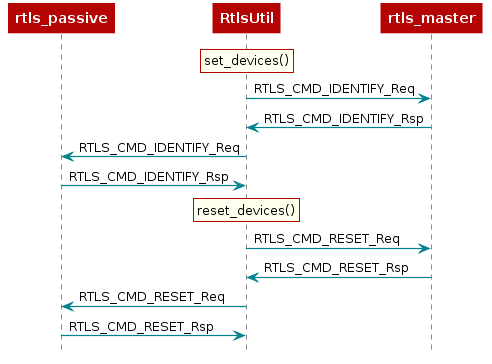
Next, create a dictionary of devices and pass this to RTLS.set_devices() which
will create RTLSNode's for each device and an RTLSManager class using these
nodes.
devices = [
  {"com_port": "COM32", "baud_rate": 460800, "name": "CC26x2 Master"},
  {"com_port": "COM26", "baud_rate": 460800, "name": "CC26x2 Passive"},
]
Note
The "name" field above does not affect the functionality. It is simply used for logging purposes and therefore it is not required to modify this if not desired.
RTLS.set_devices() will send RTLS_CMD_IDENTIFY to each node to identify it's capabilities
and set the relevant master / passive(s).
Next, reset both nodes:
rtlsUtil.reset_devices()
The procedures above will appear, from a UNPI perspective, as the following:
RTLS Network Setup Procedure
At this point you should have a basic understanding of RTLS classes. Next we will cover the minimum commands required to setup an RTLS network.
In which Python file would you find the UNPI command definitions for the ToF?
The embedded examples in the SDK will synchronize localization measurements on a
connection. In this case, a measurement can be ToF interleaved with the BLE
connection events, AoA measuring the CTE embedded in the connection packets, and / or
RSSI and channel information from CCI. In all cases a BLE connection is a
prerequisite for performing localization. The sequence diagram below shows the
UNPI commands required to establish a connection between rtls_master and rtls_slave.
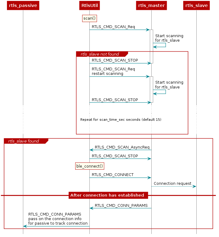
As covered in the BLE connections lab, before connecting, a scan must be
performed to see if the desired device is nearby. This is initiated by RtlsUtil.scan().
The scanning device will inspect the advertisement and optionally the scan response
data to determine if it wishes to connect to a given advertiser. Usually the
scanner is looking for a given token or string in the broadcast data of the advertiser.
The RTLS master will look for the string {'R','T','L','S','S','l','a','v','e'} starting
at the 3rd byte of the slave's advertisement data. If the advertising device
matches the filter, then it will be reported to the PC/Node Manager as
RTLS_CMD_SCAN responses which are returned from RtlsUtil.scan() as a list of
devices. If the advertising device does not match the filter, it will be discarded.
RtlsUtil.ble_connect() can be used to form a connection to one of the devices in the
scan results. This will inform rtls_master to form a connection by issuing an
RTLS_CMD_CONNECT along with the peer device's address and address type.
The address information can be extracted from the RTLS_CMD_SCAN responses
coming from the master node.
If the connection is successful, the RTLS_CMD_CONNECT response will be
received with status of RTLS_SUCCESS and RtlsUtil.ble_connect() will return.
The RTLS examples do not consider a connection to be established between master
and slave until the devices have paired and formed an L2CAP Connection Oriented
Channel (CoC). The L2CAP CoC is used to send RTLS sync related information
between master and slave. This can include AoA parameters or ToF parameters,
or a command to enable AoA or ToF.
Immediately after the BLE connection is established
(i.e. GAP_LINK_ESTABLISHED_EVENT received from the stack), the rtls_master
will share the connection parameters with the PC/Node Manager via
RTLS_CMD_CONN_PARAMS. This information is needed by the connection monitor
inside rtls_passive in order to follow the connection between RTLS master
and slave.
Distributing Connection Parameters
The RTLSManager Python class will immediately relay any connection
parameters received (RTLS_CMD_CONN_PARAMS) to all of the passive nodes
connected. This does not need to be done manually.
Setting up RTLS Network in Python
Now that we understand the basics behind the RTLS network and how to set it up,
let's review how the rtls_example_with_rtls_util.py sample app sets up the RTLS network.
Note that the rtls_example_with_rtls_util.py will do some additional processing after the
network is setup based on AoA or ToF. This is outside of the scope of this lab
and will be covered in the following AoA and ToF labs respectively.
The commands required to setup a network belong to the RTLS UNPI subsystem and
can be found in the ss_rtls.py file. The sending and receiving of these commands
is abstracted through the RtlsUtil class.
Scanning for Devices
We will use the rtls_example_with_rtls_util.py as a starting point. From the sections
above, we know that after the nodes are identified, we want to tell the master
to scan. This is initiated as such:
scan_results = rtlsUtil.scan(scan_time_sec)
Alternatively, it is possible to only scan for a specific device address by passing a second "address" parameter as such:
scan_results = rtlsUtil.scan(scan_time_sec, slave_bd_addr)
After the scan completes (runs for scan_time_sec), the results are returned in
scan_results as a list of the following dictionaries:
{
    "addr" : 6 byte address as string,
    "addrType" : address type as int,
}
Asynchronous vs Synchronous commands in UNPI
The following provides more information about the RTLS UNPI commands. As mentioned
above, all of this is abstracted through RtlsUtil so can be skipped if desired.
You might have noticed that RTLS_CMD_SCAN is used to tell the node to start
scanning, receive status, and receive scan results.
This is possible within UNPI because each message can be one of the following
types
- Synchronous request
- Synchronous response
- Asynchronous request
In the case of RTLS_CMD_SCAN the message that initiates the scan on the
rtls_master is a synchronous request. The message that returns the status
of the scan start call is a synchronous response, and the message that
returns scan results is an asynchronous request. See the NPI chapter
in the TI BLE-Stack User's Guide
for more information.
Connecting to a Device
Now, we have collected a list of scan results and are ready to connect. It is required to specify an address to connect to. The address can be hard-coded:
  slave_bd_addr = "80:6F:B0:1E:38:C3"
  rtlsUtil.ble_connect(slave_bd_addr, connect_interval_mSec)
If you don't know the address, you can read it from the UART
display of the slave device. Open a Serial terminal (like putty or Tera Term)
on the user/UART port of the rtls_slave LaunchPad. Use 115200 baud, 8N1.
It should show the following text:
Initialized
Dev Addr: 0x806FB01E3A8B
Advertising
Alternatively, the address can be extracted from the scan results as such:
rtlsUtil.ble_connect(scan_results[0], connect_interval_mSec)
Connection Interval
It is also necessary to pass a connection interval into RtlsUtil.ble_connect().
The ramifications of this parameter will be discussed in the various RTLS mode
documentation sections where relevant. The out-of-box example uses 100
milliseconds by default.
Remember, the rtls_master will automatically send the connection parameters
once a BLE connection is formed with the rtls_slave. The RTLSManager python
class will intercept this and distribute it to all rtls_passive nodes so we
don't have to do this in our program. Upon receiving the connection parameters,
the rtls_passive connection monitor will begin following the connection between
master and slave. Note that it may take some time to establish a connection as this
does include LE Secure Connections pairing as well as opening an L2CAP
Connection Oriented Channel.
Enabling Localization
Now that the connection has been formed and the connection parameter information has been distributed, it is time to enable one or more localization modes. Note that only CCI will be discussed here. AOA and TOF are detailed in their respective SimpleLink Academy's.
Continuous Connection Information
CCI is the default functionality of the out-of-box rtls_example_with_rtls_util.py. It is the
most simplistic method and only provides a received signal strength indicator (RSSI) and
frequency channel index for each BLE connection event.
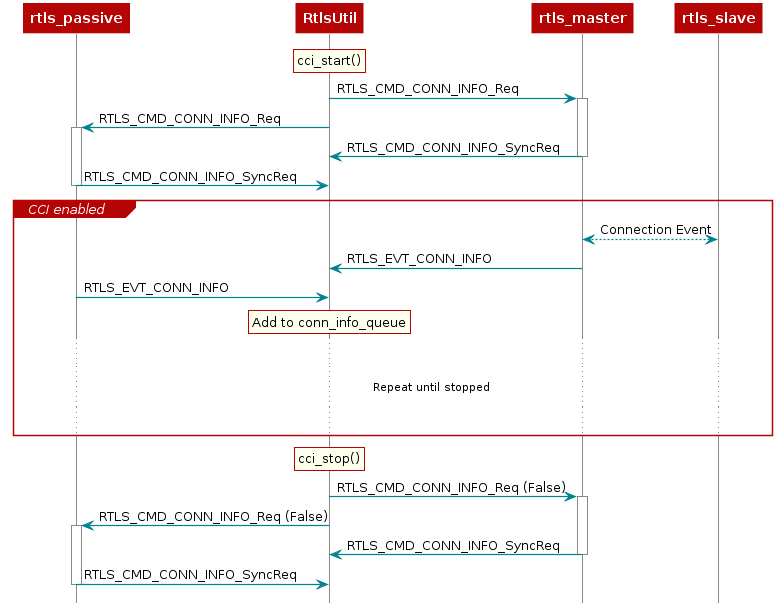
CCI can be enabled on both the master and the passive(s) by sending a RTLS_CMD_CONN_INFO UNPI
request. This is abstracted and initiated from RtlsUtil as such:
rtlsUtil.cci_start()
After being enabled, the respective node will send a RTLS_EVT_CONN_INFO UNPI Asynchronous Response
after each master-slave connection event. This response contains the RSSI and the channel of the
connection event. The master will send this after participating in the connection
event with the slave and the passive will send this after it observes the connection event.
RtlsUtil will receive each response and append it to the RtlsUtil.conn_info_queue. This queue
can then be processed as desired. The out-of-box example periodically reads and prints
from this queue in results_parsing() in a separate thread.
This procedure is shown here:
Miscellaneous Functionality
Stopping the Example
After enabling the localization mode(s), rtls_example_with_rtls_util.py will sleep for 5 seconds then
gracefully stop all ongoing over-the-air procedures and any spawned result-processing threads. If it is
desired to run for longer than 5 seconds, simply update the timeout_sec in the following code:
  timeout_sec = 5
  print("Going to sleep for {} sec".format(timeout_sec))
  timeout = time.time() + timeout_sec
  while timeout >= time.time():
      time.sleep(0.1)
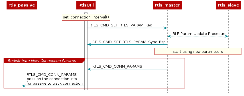
Updating Connection Interval
It is possible to dynamically update the connection interval of the master-slave BLE connection after
the connection has been established via RtlsUtil.set_connection_interval():
new_connect_interval_mSec = 80
rtlsUtil.set_connection_interval(new_connect_interval_mSec)
The new connection parameters are automatically distributed from the node manager to the passive devices so that they capable of maintaining synchronization with the connection after the update occurs. The procedure is shown here:
Any effects this has on AOA and TOF are discussed in the respective SimpleLink Academy.
You made it to the end
Excellent work!
This work is licensed under a Creative Commons Attribution-NonCommercial-NoDerivatives 4.0 International License.