Secondary Bootloader flow in AM26x devices#
7 min read
This module explains how boot happens on an AM26x device after the RBL execution is completed.
What is SBL ?#
This secondary bootloader is configurable bootloader option to load multiple applications from multiple CPUs at the same time. This can also be updated easily as compared to the ROM bootloader. This is the FIRST USER OWNED piece of software running on the device.
Note
The SBL delivered in SDK is an example implementation. User is free to modify/change or develop their custom bootloader.
In MCU PLUS SDK, the SBL is responsible for :
Initialization of clocks
Executing the PBIST(self-test) on memories
Loading the HSMRt Firmware
Loading the MultiCore Application images into the memories
Running the Application images
The flashing tools are also delivered as SBL to reduce dependencies during the flashing process. For more details on the flashing tools, CLICK HERE.
More details on SBL is present here.
Understanding Eclipse#
Eclipse is a mechanism in which the Public ROM completely shuts-off (and should not be reopened again in the current reset cycle) and the memory is remapped with TCM Memory. This is a handover mechanism from Public ROM execution to SBL execution.
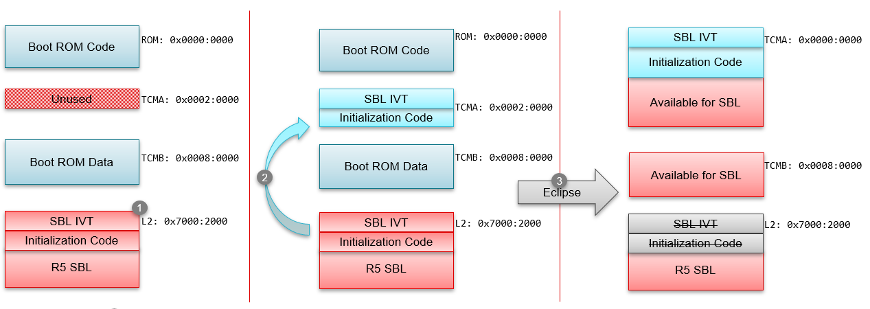
Step 1
R5 SBL is copied by Public ROM into the memory at 0x70002000 location.
Step 2
ROM will copy SBL IVT and Initialization code i.e 640Bytes to TCMA RAM at 0x20000 These addresses are fixed and are not configurable.
Step 3
Public ROM will be eclipsed by HSM ROM. In the eclipse, the TCMA address will be mapped to R5 BootROM address 0x0, R5FSS0-0 core will be reset and the execution starts from the new IVT at 0x0 i.e. for SBL.
SBL Image Creation Guide#
RBL loads the image from external source to RAM in a single blob. So tiarmobjcopy tool is used to create the binary image. The image loading happens at 0x70002000 and post eclipse the data of 640 bytes is copied by RBL and hardware eclipse mechanism to 0x0. So, the SBL image is required to have IVT placed at the top of the image. Also the IVT section and the software expected at TCM within 640 bytes is supposed to loaded at 0x70002000 but the run address for the same will be 0x0. This needs to be handled in the linker of the SBL images. An example for the same is mentioned below -
.sbl_init_code: palign(8), fill=0xabcdabcd
{
    *(.vectors) /* IVT is put at the beginning of the section */
    . = align(8);
} load=0x70002000, run=0x0
.vectors:{} palign(8) > 0x70002000
GROUP {
    .text:   {} palign(8)
    .text.hwi: palign(8)
    .text.cache: palign(8)
    .text.mpu: palign(8)
    .text.boot: palign(8)
    .data:   {} palign(8)
    .rodata: {} palign(8)
} > 0x70002280
Clocking Configuration in SBL#
Clocking in AM263x#

There are 2 external clocks - XTALCLK i.e. 25MHz and EXT_REF which can go upto 50MHz.
The CORE PLL are configured at 2000MHz to provide -
DPLL_CORE_HSDIV0_CLKOUT0 as 400MHz
DPLL_CORE_HSDIV0_CLKOUT1 as 500MHz
DPLL_CORE_HSDIV0_CLKOUT2 as 400MHz
The PERIPHERAL PLL are configured at 1920MHz to provide -
DPLL_PER_HSDIV0_CLKOUT0 as 160MHz
DPLL_PER_HSDIV0_CLKOUT1 as 192MHz
RCCLK_10M 10Mhz is an internal oscillator providing 10MHz. RCCLK_32K 32Khz is an internal oscillator providing 32KHz. TCK provides 10Mhz.
This is a standard PLL configurations. Each IP module clock configurations are configured in the SystemInit() –> PowerClock_init() APIs in MCU_PLUS_SDK. Most of the configurations are generated via SYSCFG as part of application software.
Clocking in AM263Px#
There are 2 external clocks - XTALCLK i.e. 25MHz and EXT_REF which can go upto 50MHz.
The CORE PLL are configured at 2000MHz to provide -
DPLL_CORE_HSDIV0_CLKOUT0 as 400MHz
DPLL_CORE_HSDIV0_CLKOUT1 as 500MHz
DPLL_CORE_HSDIV0_CLKOUT2 as 400MHz
The PERIPHERAL PLL are configured at 1920MHz to provide -
DPLL_PER_HSDIV0_CLKOUT0 as 160MHz
DPLL_PER_HSDIV0_CLKOUT1 as 192MHz
RCCLK_10M 10Mhz is an internal oscillator providing 10MHz. RCCLK_32K 32Khz is an internal oscillator providing 32KHz. TCK provides 10Mhz.
This is a standard PLL configurations. Each IP module clock configurations are configured in the SystemInit() –> PowerClock_init() APIs in MCU_PLUS_SDK. Most of the configurations are generated via SYSCFG as part of application software.
Loading of HSM Run Time Firmware (or TIFS-MCU Firmware)#
Note
This maybe an optional step for HSFS devices, but is an mandatory step for HSSE devices. For more details understand the Security on AM26x devices
The SBL issues a request to HSM ROM via IPC which is waiting for a request to load the HSM Run Time Firmware. This function can be found in source/drivers/hsmclient/soc/am263x/hsmclient_loadhsmrt.c More details about the same is mentioned HERE.
What is HSMRt Firmware ?#
The security services provided by HSM ROM are primarily for SBL load and verification. The higher amount of services in a ROM may lead to higher complexity which increases the risk as well as attack surface. Configurability is a major requirement for security services for boot time as well as run time. This is where HSM Run Time Firmware provides a configurability with higher complexity than BOOT ROM as well as support of updatability in case of issues.
Loading of Application Software#
Software Load into the memory#
Application software needs to be loaded into the memory. The available memories are TCM memories of respective sub-system and L2OCRAM.
The parsing logic is based on Multi Core Image format and RPRC format.
Link to Individual Core Image Format
Link to Multi Core Image Format
Ungating the Application Cores#
As mentioned above, the PLLs are configured by the SBLs but the other-R5 cores (R5SS0-1, R5SS1-0, R5SS1-1) are not ungated/enabled. Based on the application images available in the device, the bootloader ungates the Application Cores.
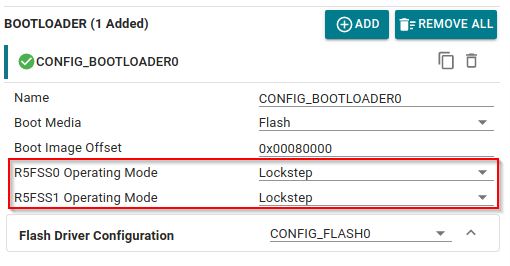
Configurability of Lockstep and Dual Core#
Sysconfig provides an option to configure the Lockstep and Dual Core settings via SYSCFG for SBL projects.
List of Collaterals on Secondary Boot Loader#
Collateral Title |
Collateral Type |
Collateral Link |
|---|---|---|
MCU-PLUS-SDK-AM263X: How to understand/optimize the boot time of RBL/SBL ? |
E2E FAQ |
|
MCU-PLUS-SDK-AM263X: Important SBL Links |
E2E FAQ |
|
Cortex R5 - Dual core/lockstep configuration |
E2E FAQ |
|
How to debug SBL_QSPI / SBL_OSPI or an application directly booted via QSPI/OSPI ? |
E2E FAQ |
|
SBL NULL |
MCU+ SDK Documentation |
|
SBL OSPI |
MCU+ SDK Documentation |
|
SBL UART |
MCU+ SDK Documentation |
|
SBL CAN |
MCU+ SDK Documentation |
|
SBL SD |
MCU+ SDK Documentation |