ROM Boot Flow in AM26x devices#
12 min read
This module explains how boot happens on an AM26x device.
Top Level Boot Flow#
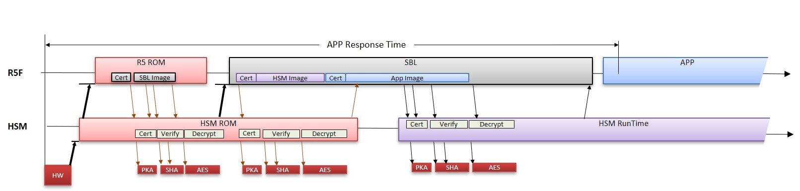
After the reset is de-asserted, Cortex M4 which is part of HSM sub-sysytem is booted first in the device. The Cortex M4 CPU executing HSM ROM will boot R5FSS0-0 CPU to execute Public ROM. After identifying the boot mode, the public ROM copies the image from the source into the device memory i.e. L2 OCRAM. This image is called secondary bootloader. This complete process of booting the SBL is called ROM Bootloader.
Note
In this documentation, ROM and RBL may be used synonymously.
What is RBL ?#
The ROM bootloader is placed on secure, read-only memory for security reasons and to have a known state always before application software starts. The complexity of the bootloader due to its fixed nature is relatively lesser to avoid issues. The prime requirement of RBL or ROM bootloader is to bring in the SBL image from external world and load the same in the internal memory. In case of HS-SE device, security goals are also considered. For more details on secure boot, checkout the academy chapter of SECURE BOOT HERE..
Why HSM ROM and Public ROM ?#
As per the top level boot flow, M4 Core is booted first into the system which is part of security subsystem. M4 Core is responsible for booting the R5FSS0-0 core to execute public ROM.
HSM ROM is primarily responsible for providing boot-time security in the system to Public ROM. It includes boot time firewalls, security services including key management, certificate management, asset management, anti-rollback protection and debug configuration.
Public ROM is primarily standard functionality executing on R5SS0-0 which utilizes public peripheral like OSPI/QSPI controller, UART (in case of UART boot mode) for boot. The logs are also recorded by R5 ROM in TCM memories.
HSM ROM and Public ROM communicate via IPC.
Note
HSM ROM security services are exclusively provided for Public ROM. Hence, the same is not documented. However the HSM ROM provides 1 service to SBL for loading of HSM Run Time Firmware. The same is documented here.
Memory Test#
Before booting the SBL, the RBL initiates a self-test sequence on the mentioned memories :
ATCM0 R5SS0 (32KB)
ATCM0 R5SS1 (32KB)
BTCM0 R5SS0 (32KB)
BTCM0 R5SS1 (32KB)
L2 RAM Bank 0 (512KB)
L2 RAM Bank 1 (512KB)
RBL boots SBL#
ROM bootloader boots the secondary bootloader. The RBL boots the device based on the boot mode mentioned below -
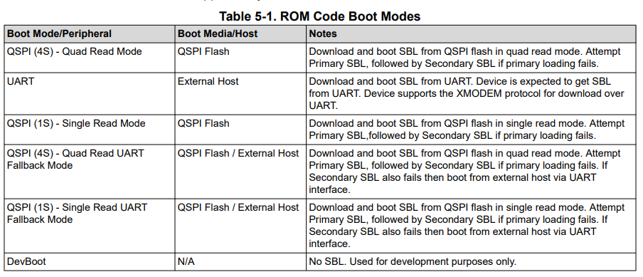
The mapping of the following boot modes to SOP (BOOTMODE pins) boot pins are mentioned in the Device Technical Reference Manual.
Note
xSPI boot mode (8D) and OSPI boot mode (8S) are only supported in AM263Px.
xSPI boot mode (8D)#
8D-8D-8D mode of controller configuration.
The Command and Address issued are 8 bits and 24 bits respectively. Both command and address are transferred on 8 lines.
Number of dummy cycles are 8.
The frequency of operation supported is 25 MHz.
The command used for read are read via SFDP table.
The data is read over 8 lines.
Note
Flashes with SFDP and supporting JEDEC standard Rev D are only supported for this boot mode.
OSPI boot mode (8S)#
1S-1S-8S mode of controller configuration.
The Command and Address issued are 8 bits and 24 bits respectively. Both command and address are transferred on single line.
Number of dummy cycles are 8.
The frequency of operation supported is 50 MHz.
The command used for read are 0x8B.
The data is read over 8 lines.
QSPI boot mode (4S)#
1S-1S-4S mode of controller configuration.
The Command and Address issued are 8 bits and 24 bits respectively. Both command and address are transferred on single line.
Number of dummy cycles are 8.
The frequency of operation supported is 50 MHz.
The command used for read are 0x6B.
The data is read over 4 lines.
SPI boot mode (1S)#
1S-1S-1S mode of controller configuration.
The Command and Address issued are 8 bits and 24 bits respectively. Both command and address are transferred on single line.
Number of dummy cycles are 8.
The frequency of operation supported is 50 MHz.
The command used for read are 0x0B.
The data is read over 1 lines.
UART boot mode#
UART_0 to transfer the data.
115200 baud rate.
8-n-1 mode.
Protocol used is XMODEM.
Dev boot mode#
Warning
This boot mode is only valid for HS-FS devices.
This mode allows users to load the software via debugger during the development phase.
Boot Locations for SBL#
In case of memory based boot like OSPI or QSPI boot mode where the image is read from the external flash the boot locations are fixed by ROM.
For AM263x, there are 2 boot locations supported. The primary boot location supported is 0x0 and the secondary boot location supported is 0xF0000. The image is always verified for 0x0 first before falling back to secondary boot location.
For AM263Px, there are 4 boot locations supported. The primary boot location supported is 0x0 and the secondary boot locations supported are 0x20000, 0x40000, 0x60000. The image is always verified for 0x0 first before falling back to subsequent boot location. Successfully booted flash image offset address is available at 0x84100 address.
When does RBL resets the device ?#
In case RBL is not able to find the valid SBL image in the device at any of the valid boot locations or if the RBL does not receive a valid image via UART, there is a Windowed Watchdog Timer with an expiry of 180secs i.e. 3 mins. If the WWDT is expired, the device undergoes a warm reset.
RBL Logs#
During the boot up time, log entries are stored in TCMB memory at 0x80000 memory location.
Log format#
Logger memory section will contain the following fields as part of each log entry -
Log Type (32-bit) : Logging Level.
Log_Type_INFO: Informational logs
Log_Type_WARNING: warning logs
Log_Type_ERROR: error logs
Log_Type_CRITICAL: critical error logs
Filename (8-bit) : File generated the log entry.
Line Number (32-bit) : Line number in the source file which generated the log entry.
Value1 (32-bit) : Error/Informational message generated by the log entry.
Value2 (32-bit) : Error/Informational message generated by the log entry.
Time ticks (64-bit) : Time in ticks when the log entry was created.
Supported Certificate format#
The X.509 certificate is defined in Annex A of ITU-T X.509 specification. Certificate is encoded using ASN.1 encoding with DER (Distinguished Encoding Rules). Essentially, the signed certificate is the concatenation of the certificate itself and the signature. Certificate includes mandatory and optional fields. The supported version shall be v2.
Here is a template file of Boot Certificate supported by ROM.
[ req ]
distinguished_name = req_distinguished_name
X509_extensions = v3_ca
prompt = no
dirstring_type = nobmp

[ req_distinguished_name ]
C = GB
ST = HI
L = Boston
O = Texas Instruments., Inc.
OU = DSP
CN = Bob
emailAddress = Bob@hou.ti.com

[ v3_ca ]
basicConstraints = CA:true
1.3.6.1.4.1.294.1.1 = ASN1:SEQUENCE:boot_seq
1.3.6.1.4.1.294.1.2 = ASN1:SEQUENCE:image_integrity
1.3.6.1.4.1.294.1.3 = ASN1:SEQUENCE:swrv
1.3.6.1.4.1.294.1.4 = ASN1:SEQUENCE:encryption
1.3.6.1.4.1.294.1.5 = ASN1:SEQUENCE:key_derivation
1.3.6.1.4.1.294.1.8 = ANSI:SEQUENCE:debug

[ boot_seq ]
certType =INTEGER:1
bootCore = INTEGER:16
core_opts = INTEGER:32
destAddr = FORMAT:HEX,OCT:bc934b00
imageSize = INTEGER:0x00004860

[ image_integrity ]
shaType = OID:2.16.840.1.101.3.4.2.3
shaValue = FORMAT:HEX,OCT:4cf4d59ef77b5d9ab28d2ceb3c9fe83cb52ae6d2

[ swrv ]
rollback = INTEGER:0x00010001

[ encryption ]
Iv =FORMAT:HEX,OCT:00112233445566778899aabbccddeeff
Rstring = FORMAT:HEX,OCT:00112233445566778899aabbccddeeff101112131415161718191a1b1c1d1e1f
Icount = INTEGER:1
Salt = FORMAT:HEX,OCT:00112233445566778899aabbccddeeff

[ debug ]
uid = FORMAT:HEX,OCT:00345678900
type = INTEGER:1
dbgE = INTEGER:0
secDbgEn = INTEGER:0
Boot Information OID (1.3.6.1.4.1.294.1.1)#
The Boot Information Object identifier provides information about the image which is being loaded. This information is mandatory and needs to be present in the all the X.509 certificates else the image boot will fail.
Certificate Type#
The certificate type defines the type of the image which is being loaded by the Boot-ROM. The ROM supports loading of R5 SBL Image and M4 HSM Runtime Image.
Boot Core#
The certificate type defines the type of the image which is being loaded by the Boot-ROM. The ROM supports loading of R5 SBL Image and M4 HSM Runtime Image.
Core Options#
This defines what configuration for R5SS0 will be booted by ROM. It can either be Lockstep i.e. 0 or Dual Core Mode i.e. Non Zero value.
Load Address#
Due to architectural limitations, the images of R5 SBL is supported to be loaded at 0x70002000 where as image of HSM Run Time is supported to be loaded at 0x0.
Note
Here the 0x0 address mentioned above is not R5F TCM memories. To load the HSM Run Time image the view should be M4 view. The 0x0 address translates to Secure IRAM available in HSM subsystem.
Image Integrity OID (1.3.6.1.4.1.294.1.2)#
Boot-ROM will perform the SHA-512 on the entire image and will verify the computed hash with the hash provided in the boot extension. In the case of a mismatch the boot will fail.
DEVICE_TYPE |
IMAGE TYPE |
STATUS |
|---|---|---|
HS-FS |
SBL Image |
Optional |
HS-FS |
HSM Run Time Image |
Mandatory |
HS-SE |
SBL Image |
Mandatory |
HS-SE |
HSM Run Time Image |
Mandatory |
Software Revision OID (1.3.6.1.4.1.294.1.3)#
The anti-rollback protection is valid only for HS-SE devices. The image certificate should be greater than or equal to the image certificate. For more information on eFuses and TIFS-MCU services of programming SW Revision is available here.
Image Encryption OID (1.3.6.1.4.1.294.1.4)#
The Boot-ROM only supports AES-CBC mode with 256bit root keys.
Note
For SBL Image, in an HS-FS device encryption is not supported.
Initialization Vector#
The initialization vector is used during the AES-CBC decryption procedure. The initialization vector needs to be 16bytes.
Random String#
The random string is a 32 byte long which is appended at the end of the image. ROM will decrypt the image and then compare the last decrypted 32 bytes with the RString as part of the certificate.
Iteration Count#
Iteration Count is used to determine if the HKDF needs to be performed and key derivation needs to be done. If the iteration count is 0 then the key from the e-fuse is used as is for the decryption. If the iteration count is non-zero then the Boot-ROM will perform the HKDF key derivation using the salt. The derived key is then used for the decryption operation.
Salt#
The salt is used only if the iteration count is non-zero and key derivation is being done. The salt is fed to the HKDF module to derive the key. The salt fields should be 32bytes.
Debug OID (1.3.6.1.4.1.294.1.8)#
UID#
This is the unique identifier associated with the device. This value can be retrieved by either using TIFS-MCU service or by using SOC ID Parser tool.
Warning
Setting the UID as ‘0’ is a special wildcard specification which allows UID check to be bypassed in the ROM. This makes the same certificate to be reused on any device if the certification verification is successful.
Key Protections#
If set as 0 will allow access to all the customer keys otherwise it will disable access to all the customer keys.
Debug Type#
DEBUG LEVELS |
Description |
|---|---|
0 |
Disable debug |
1 |
Preserve debug state |
2 |
Enable non-secure debug (Public Debug) |
List of Collaterals on Boot Flow#
Collateral Title |
Collateral Type |
Collateral Link |
|---|---|---|
Understand the bootloaders/SBL in SDK |
SDK DOCUMENTATION |
|
Understanding the Secure Boot via SDK |
SDK DOCUMENTATION |