Over the Air Download#
Texas Instruments
2 hours read
This module covers the basics of the TI Wi-SUN OAD (Over the Air Download) and leads you through an example. It is assumed that the reader is familiar with the SimpleLink™ TI Wi-SUN FAN Fundamentals and has a basic knowledge of general C programming concepts. This lab is intended as a starting point for users who want to get familiar with OAD concepts and performing a firmware update.
Introduction#
OAD refers to the ability for an application to download a new executable image, over the air. A number of software components are involved in this process and TI uses OAD to refer to all of them as a software system.
This lab will cover an overview of a typical TI Wi-SUN-Stack image and examine the
high level anatomy of an OAD image. The first task will be to setup the
environment to enable OAD. The next task will be performing the OAD firmware
update.
First you need to decide what type of OAD you want to use. You have the choice between Off-Chip OAD and On-Chip OAD. Off-Chip OAD allocates a buffer on Off-Chip flash memory to store the incoming image. On-Chip OAD allocates the same buffer on spare On-Chip memory. Make sure that your hardware supports the chosen type of OAD.
During the lab you’ll often find the following switch options. This is because the lab covers both On-Chip and Off-Chip OAD. Please make sure you always select the option you need. The default selection is Off-Chip OAD and the selected case is always highlighted in red.
This content will be related to Off-Chip OAD applications.
This content will be related to On-Chip OAD applications.
Warning
Do not mix On-Chip images with an Off-Chip setup and vice versa as this will lead to a failing boot up.
Prerequisites#
For this lab you need the specified hardware and software.
Hardware#
You need two TI Wi-SUN FAN enabled development boards. Supported devices are:
These devices are interchangeable in the lab.
Software for desktop development#
Python v.3.6.8 or later (including pip)
CCS installed with support for CC13xx/CC26xx devices
Note
The software is already installed if you completed the SimpleLink™ TI Wi-SUN FAN Fundamentals. If you have problems with the installation, please go back there.
Recommended reading#
Note
This lab expects that you already know how to setup a TI Wi-SUN FAN according to the SimpleLink™ TI Wi-SUN FAN Fundamentals.
Furthermore, it is recommended to review the OAD Chapter of the SimpleLink™ TI Wi-SUN Stack User’s Guide before starting this lab.
Getting started – Desktop#
In the next step, you import the software projects used in the lab. Then, you will adjust the settings and afterward you’re ready to compile the projects.
Import Software Projects#
Border Router: The project
ns_bris required to setup a border router for the network. It is found in theti_wisunfanexamples folder:<SDK_INSTALL_DIR>\examples\rtos\<BOARD_NAME>\ti_wisunfan\ns_br\tirtos7CoAP Node Off-Chip OAD: The example will use the
ns_coap_oad_offchipproject that supports OAD. It is found in theti_wisunfanexamples folder:<SDK_INSTALL_DIR>\examples\rtos\<BOARD_NAME>\ti_wisunfan\ns_coap_oad_offchip\tirtos7CoAP Node MCUBoot: The project will use the
mcubootproject that supports OAD. It is found in themcuboot_appexamples folder:<SDK_INSTALL_DIR>\examples\nortos\<BOARD_NAME>\mcuboot_app\mcuboot
Border Router: The project
ns_bris required to setup a border router for the network. It is found in theti_wisunfanexamples folder:<SDK_INSTALL_DIR>\examples\rtos\<BOARD_NAME>\ti_wisunfan\ns_br\tirtos7CoAP Node On-Chip OAD: The example will use the
ns_coap_oad_onchipproject that supports OAD. It is found in theti_wisunfanexamples folder:<SDK_INSTALL_DIR>\examples\rtos\<BOARD_NAME>\ti_wisunfan\ns_coap_oad_onchip\tirtos7\CoAP Node MCUBoot: The project will use the
mcubootproject that supports OAD. It is found in themcuboot_appexamples folder:<SDK_INSTALL_DIR>\examples\nortos\<BOARD_NAME>\mcuboot_app\mcuboot
Note
The CoAP Node OAD project provides the same functionality as the CoAP Node. Only the OAD option is added.
Configure Software Projects#
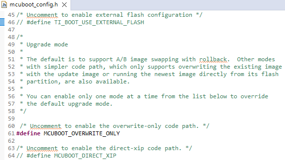
Open the MCUBoot Project in your IDE and double check the files according to the following steps:
In the file
<mcuboot>\mcuboot_config\mcuboot_config.hUncomment
#define TI_BOOT_USE_EXTERNAL_FLASHso it is definedUncomment
#define MCUBOOT_OVERWRITE_ONLYso it is definedComment out
#define MCUBOOT_DIRECT_XIPto undefine it

Define
TI_BOOT_USE_EXTERNAL_FLASH,MCUBOOT_OVERWRITE_ONLYand undefineMCUBOOT_DIRECT_XIP#In the file
<mcuboot>\flash_map_backend\flash_map_backend.hfile:Find the definitions for
BOOT_PRIMARY_1_BASE_ADDRESS,BOOT_PRIMARY_1_SIZE,BOOT_SECONDARY_1_BASE_ADDRESSandBOOT_SECONDARY_1_SIZE. There should be several, but only one set defined for the platform you are currently using (CC13x2x7 or CC13x4).If using a CC13x2x7 platform, no changes are required.
If using a CC13x4 platform, modify the values above to the following:
#define BOOT_PRIMARY_1_BASE_ADDRESS     0x00006000
#define BOOT_PRIMARY_1_SIZE             0x00056000
#define BOOT_SECONDARY_1_BASE_ADDRESS   0x0005C000
#define BOOT_SECONDARY_1_SIZE           0x00056000

Address adjustments for the CC13x4 device family#
Open the MCUBoot Project in your IDE and change the files according to the following steps:
In the file
<mcuboot>\mcuboot_config\mcuboot_config.hComment out
#define TI_BOOT_USE_EXTERNAL_FLASHto undefineUncomment
#define MCUBOOT_OVERWRITE_ONLYso it is definedComment out
#define MCUBOOT_DIRECT_XIPto undefine it
Undefine
TI_BOOT_USE_EXTERNAL_FLASH, defineMCUBOOT_OVERWRITE_ONLYand undefineMCUBOOT_DIRECT_XIP#In the file
<mcuboot>\flash_map_backend\flash_map_backend.hfile:Find the definitions for
BOOT_PRIMARY_1_BASE_ADDRESS,BOOT_PRIMARY_1_SIZE,BOOT_SECONDARY_1_BASE_ADDRESSandBOOT_SECONDARY_1_SIZE. There should be several, but only one set defined for the platform you are currently using (CC13x2x7 or CC13x4).If using a CC13x2x7 platform, no changes are required.
If using a CC13x4 platform, modify the values above to the following:
#define BOOT_PRIMARY_1_BASE_ADDRESS     0x00006000
#define BOOT_PRIMARY_1_SIZE             0x00056000
#define BOOT_SECONDARY_1_BASE_ADDRESS   0x0005C000
#define BOOT_SECONDARY_1_SIZE           0x00056000
Adjustments for the CC13x4 device family#
For more information about MCUBoot you can have a look at the following chapter MCUBoot and OAD Image Header or at the MCUBoot documentation.
Hint
If you have difficulties to find the #define you can use the file search in
CCS which you can access by the shortcut ctrl + f.
Build Software Projects#
Now you are ready to compile the projects. Select each of the projects in CCS and click on the hammer icon, like shown below, to build the projects. The build process will take a while. So please make sure that all changes have been made correctly before you start the build process. You can spend the waiting time with reading the following theory section about OAD. After the builds have finished you can continue with Task 1 – Setting up the OAD Environment.

Build the project by clicking on the hammer icon#
Anatomy of an OAD#
This section seeks to explain the various components involved in an OAD image from a high level. We start by introducing the terms OAD Distributor and OAD Target.
The OAD Target is the device that receives the incoming image over the air. It is responsible for implementing the protocol stack specific transport layer that is used for sending and receiving OAD image data. In this lab a TI LaunchPad is used as OAD Target.
The OAD Distributor is responsible for fragmenting the new firmware image into protocol stack specific packets and sending them over the air. It may take any form. Below it is illustrated how you will use it in this lab. A TI LaunchPad serves as Border Router and it’s connected to an associated PC tool which is the network Host.

OAD Distributor (Host computer + LaunchPad) and OAD Target (LaunchPad)#
Default Non OAD Image#
We will begin with the template for a standard TI Wi-SUN stack image that does not have OAD enabled.
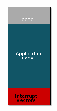
Image without OAD#
There are three main components of this image:
The instructions/constants that implement the compiled form of the program (application code)
The reset vectors in the ARM Cortex M format (which are always found at the beginning of the flash): ARM Cortex M4F Vector Table
The CCFG, which contains chip configuration parameters, see the Technical Reference Manual
These three components are required for any image that is to run on the CC13xx. The goal of OAD is to get an executable image of this form on the device via an over the air update, no JTAG or wires required.
However, in order to achieve the goal of making the image pictured above upgradeable over the air, a few software components must be set in place.
MCUBoot and OAD Image Header#
A running image cannot update itself. This means that the incoming OAD image must be stored in a temporary location while it is being received. On-Chip OAD allocates spare On-Chip flash memory as a buffer to store the incoming image and Off-Chip OAD allocates this same buffer on Off-Chip flash memory.
After the download is complete, a reboot is required. During the reboot some code must determine if the new image is valid or if the current image should be overwritten. Finally, it has to execute the new image.
Therefore, the MCUBoot bootloader is used.
MCUBoot is intended to permanently remain on the device, meaning it persists through many OADs and cannot be updated.
MCUBoot will run every time the device boots and determine if a new image should be loaded and run (based on the image header).
MCUBoot and the CCFG structure are tied together, because both are required for a successful device boot.
The CCFG is needed to boot correctly. By default the boot ROM will
jump to address 0x00000000 and look for a vector table, but this region is
now occupied by the image header. A custom CCFG must be used to instruct the
device to jump directly to MCUBoot.
From there MCUBoot will determine and load the optimal image based on the OAD image header containing the version number of the image.
The MCUBoot code will require more reserved space in the system. See below for the memory map after MCUBoot has been added to the last image.

Image with Header and MCUBoot#
The MCUBoot repo provides a tool to generate an OAD ready image, it is called Post-Build Script imgtool. By default, this tool runs as a post-build step of all OAD enabled projects. That generates the OAD image including the needed header.
Note
MCUBoot is responsible for linking and defining the CCFG structure, instead of the application as in the non OAD case. This ensures that the device will always execute MCUBoot after boot.
Any modifications of the CCFG must be made in the MCUBoot project.
OAD Memory Layout#
The final memory structure depends on the type of OAD in use. On-Chip OAD allocates spare On-Chip flash memory as a buffer to store the incoming image firmware upgrade. Off-Chip OAD allocates this same buffer on Off-Chip flash memory.
This section will describe the method for placing images in external flash when using Off-Chip OAD.
Requirements and Constraints for Off-chip OAD
Internal flash refers to the flash memory inside the CC13xx or CC26xx and
external flash refers to an external flash memory connected to the CC13xx or
CC26xx via SPI.
In order to perform an Off-Chip OAD the target system must have:
An Off-Chip flash storage as large as the application size + one external flash page to store the external flash image header.
A serial connection (SPI) is used to communicate with the Off-Chip flash component.
Free GPIO pins to interface to the external memory (i.e. 4 wires for SPI)
Internal Flash Memory Layout
The internal flash of the device contains the active user application and the
MCUboot application. Off-Chip OAD maximizes the available flash space to the
user application because of its ability to store the incoming image in external
flash during the download process. The right column of the image below refers to
the memory address defines from the Configure Software Projects Section.

Off-Chip OAD Image Internal#
The user application pictured above is responsible for the following:
Implementing the protocol stack specific implementation of the OAD transport.
Finding a suitable location in external flash for the image and storing its image header in the table.
External Flash Memory Layout
Currently the MCUBoot based Off-Chip OAD supports having only one downloaded
image on the external flash. The image consists of the MCUBoot Image Header, the
application and the MCUBoot Trailer. The Image Header is used to determine the
image version, as explained above. The Trailer contains metadata needed for the
image swap process. Since the overwrite method is used for TI Wi-SUN
OAD, the downloaded image must be copied to the primary slot of the internal
flash memory. The updated image will then be started at the next boot. The right
column of the image below refers to the memory address defines from the
Configure Software Projects Section.

Off-Chip OAD Image External#
This section will describe the method for placing images in internal flash when using On-Chip OAD.
Warning
For TI Wi-SUN, this is only supported on CC13x4 devices.
Requirements and Constraints for On-Chip OAD
In order to perform an On-Chip OAD the target system must have:
The user application must be sufficiently small to fit into the flash layout system described below.
Internal Flash Memory Layout
The internal flash of the device contains the active user application and the
MCUboot application. It also has a buffer allocated for the secondary image. The
MCUBoot Image Header is used to determine the image version, as explained above
and the MCUBoot Trailer contains metadata needed for the image swap process.
Once OAD is initiated by the distributor, the new image is written into the
secondary slot. When the system reboots, the MCUBoot application decides based
on the version number of the secondary image whether to boot into the new image.
If the secondary image has a higher version number than the primary image, the
secondary image is copied into the primary slot and the device boots into this
image. The right column of the image below refers to the memory address defines
from the Configure Software Projects Section.

On-Chip OAD Image#
The location of the Secondary App Image is defined in the linker cmd file.
There you can see how the memory is divided.
OAD Wi-SUN FAN Protocol#
Currently we have covered all the necessary building blocks for updating an image locally on the target device. The only missing piece is a vehicle for sending the OAD blocks over the air and storing them on the target device.
This functionality is implemented by the TI Wi-SUN FAN OAD protocol, which is explained
in detail in the SimpleLink™ TI Wi-SUN Stack User’s Guide
chapter MCUBoot Over-the-Air Download (OAD) section Wi-SUN OAD. The
implementation can be found in the file oad.c and its associated flash
wrappers.
At a high level, the tasks of the Distributor and the OAD target are the following.
Distributor
The Distributor of OAD images is the Border Router in combination with the Host.
The Distributor initiates the OAD process.
It sends OAD image blocks according to the OAD Targets requests.
OAD Target
The OAD Target is a CoAP Node.
The OAD module of its application handles the communication with the OAD image distributor which includes requesting OAD image blocks, re-requesting when required and handle error conditions.
It also manages and stores the downloaded firmware images.
Once the OAD is complete, it will reset and start running with the new image.
Task 1 – Setting up the OAD Environment#
This task will lead you through the setup steps that are required to perform an OAD using the example.
Note
If you need more information about setting up the network, please refer to the the SimpleLink™ TI Wi-SUN FAN Fundamentals.
Border Router Setup#
Connect one of the LaunchPads to your pc and flash it with the ns_br project.
It will serve as Border Router. The procedure is described in detail in the
SimpleLink™ TI Wi-SUN FAN Fundamentals.
Router Node Setup#
Use a second LaunchPad for the following steps and make sure you do not overwrite the Border Router LaunchPad.
The Router Node has to be flashed with the MCUBoot image and the application image.
Connect the second LaunchPad to your pc
Open UNIFLASH and select the LaunchPad by clicking on the
Startbutton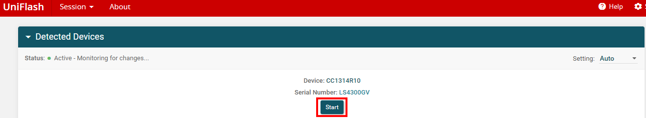
Select your device#
Add the MCUBoot image to the image list. To do this, click on the
Browsebutton and select the image in the file explorer. After selecting the correct image click onOpen.The image path is for CC13x2x7:
<CCS_WORKSPACE_DIR>\mcuboot_<BOARD_NAME>\Debug\mcuboot_<BOARD_NAME>.outand for CC13x4:
<CCS_WORKSPACE_DIR>\mcuboot_<BOARD_NAME>\TZ_Disabled\mcuboot_<BOARD_NAME>.out
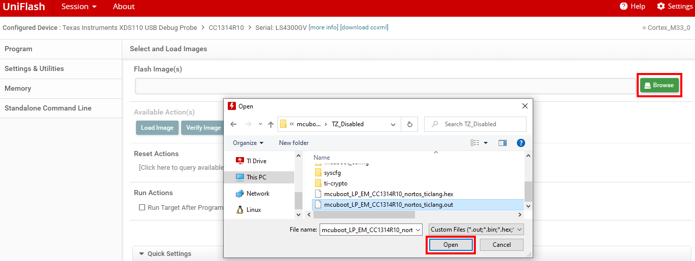
Load the MCUBoot image#
Add the Router Node image to the image list by clicking on
+ Add Another Image. Select the CoAP Node binary in the file explorer and click onOpen.The image path is:
<CCS_WORKSPACE_DIR>\ns_coap_oad_<onchip/offchip>\Release\ns_coap_oad_<onchip/offchip>.bin

Load the CoAP Node image#
Select the binary option for the CoAP Node image and modify the flash address according to the device that you’re using.
If you’re using a
CC13x2x7platform, flash at address0x0If you’re using a
CC13x4platform, flash at address0x6000
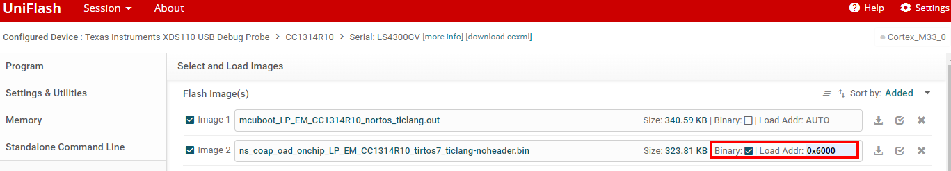
Modification of the flash address when using the
CC13x4platform#Flash the device by clicking on the
Load Imagesbutton.
Flashing Router Node with UNIFLASH#
Setup the network#
Now establish the connection between the Border Router and your host pc using the PySpinel CLI. Start the network and let the Router Node join it. If you need to review the steps look back at SimpleLink™ TI Wi-SUN FAN Fundamentals.
Note
We aim for fast join times but it can still take a while until the CoAP Node joins the network. If the Router Node has not joined the network after 15 min please restart the LaunchPad running the Router Node application by pressing the Reset button.
Start the PySpinel CLI using the following command with the COM port of the Border Router. The “Module readline unavailable” message can be ignored.
python spinel-cli.py -u COM9

CMD output of the of the start of the PySpinel CLI#
Now, start the Si-SUN FAN interface using the command ifconfig up.
ifconfig up

CMD output of the ifconfig up command#
To start the network insert the command wisunstack start.
wisunstack start

CMD output of the wisunstack start command#
To verify that the network is setup and working correctly you can use multiple PySpinel commands. First you can check the router state with the command:
routerstate
The output on the terminal should tell you that the Border Router is in state 5
which means it opened the network and is operational.

CMD output of the routerstate command#
To verify that the CoAP Node joined the network you can check the connected devices with the PySpinel command:
connecteddevices
The output on the terminal shows you a list of devices that are in the routing table of the Border Router, with their IP addresses.

CMD output of the connecteddevices command#
Now, you can use the IP address of the device which you got from the previous command to verify that the CoAP Node is operational. You can ping the device with the following command:
ping <ipv6 address>
The output shows you how many bytes have been received from the device and in which time. If you see an output like the following the device is working correctly.

CMD output of the ping command#
If you would like to gain deeper insight of the networks structure you can use the PySpinel command:
dodagroute <ipv6 address>
with the specified IPv6 address of the CoAP Node that you want to investigate. It will display you the full routing path and also the path cost.
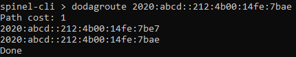
CMD output of the dodagroute command#
Task 2 – Performing an OAD#
Now that the OAD environment is ready, you will send a new image over TI Wi-SUN FAN using the PySpinel CLI.
Modifying the Image Version#
You have to create a new application image that has a higher version number than the one flashed on the device. Over the air updates with images with lower version numbers are automatically rejected.
You can request the current image version of the Router Node with the PySpinel CLI using the following PySpinel command:
getoadfwver <ipv6 address>
You use the IPv6 address of the CoAP Node which you obtained in Task 1. The terminal output shows you then clearly the current image version number as shown below.

CMD output of the getoadfwver command#
Now go back to CCS and open the Router Node application project:
<CCS_WORKSPACE_DIR>\ns_coap_oad_<onchip/offchip> and perform the following
modifications.
Right click on the project name and open the project
PropertiesNow click on
Buildand go to the tabStepsThere you see the image version number in the last postbuild step as string
--version 1.0.0like shown in the following image:
Router Node Project Properties#
Bonus Task
You can modify the application code such that the Router Node signals that the OAD firmware update is finished by:
Blinking an LED
Printing a message on the UART
Modify the image version number to a higher version number like
2.0.0and save the properties.Warning
TI Wi-SUN FAN OAD can only be performed to update the CoAP OAD Nodes device image with an image of a higher firmware version.
After modifying the image version number a rebuild of the project is required.
Right clickon the project name and select the optionRebuild Project.
Rebuild the project#
Warning
Every time you rebuild the project, the
.bin,.outand.hexfiles are overwritten. If you want to keep the previous version, you should append the version number to the file name or move the file to another directory.
OAD using PySpinel#
Now you will perform an OAD update of the CoAP Node. Therefore, you will use the
PySpinel command startoad. The syntax is the following:
startoad <ipv6 address> <platform type> <block size> <oad image path>
where the parameters have to be inserted as:
ipv6 address: Destination IPv6 address of the Target OAD-enabled device to upgrade the firmware of. Multicast addresses are not supported.
platform type: Platform of the target device to be upgraded. Supported platforms are
CC1312R7,CC1352P7,CC1314R10, andCC1354P10.block size: Block size (bytes) to use for block transfer. Recommended to use between 128-1024 byte blocks. Very small block size incurs unnecessary frame overhead, while very large block size results in fragmentation overhead.
oad image path: Relative file path of the oad image binary file to upgrade the target OAD device with.
The following steps will guide you to use the command and perform the OAD.
To easily get the file path of the image binary
right clickin CCS on the project and selectShow in→System explorer. The explorer will open the project folder. Navigate to the image binary and copy the path.The image path is:
<CCS_WORKSPACE_DIR>\ns_coap_oad_<onchip/offchip>\Release\ns_coap_oad_<onchip/offchip>.bin

Show the project in the system explorer#
Now switch back to the PySpinel terminal and type the command
startoadfill out the IP address with the CoAP Nodes IP which you obtained in Task 1, insert the platform type according to the device you are using and chose a block size for example512. Provide as last parameter the filepath of the new application image that you got in step 1. It should look like:
Startoad with example parameters#
After pressing enter, you will see in the terminal the confirmation that the OAD was started.

Startoad comfirmation#
You can check the current status of the OAD using the command
getoadstatuswhich is used in the following way:getoadstatusAnd it will show you the amount of blocks that were already sent, the used blocksize and the current duration.

OAD status#
When the OAD is completed you get notified with the following message. It also displays the total duration of the OAD.

Startoad with example parameters#
Now the CoAP Node is rebooting on its own and you have to wait until it rejoined the network. You will see that the CoAP Node rejoined the network once its red LED stops blinking and its green LED stays on. Another way to verify that the CoAP Node rejoined the network is by re-executing the
pingcommand from Task 1.Afterwards, you can check with the
getoadfwvercommand if the new application version is running.
Startoad with example parameters#
You see that now the new image version
2.0.0is running.
Hint
Congratulations, you’ve done an OAD!