|
CC26xx Driver Library
|
|
CC26xx Driver Library
|
Data Structures | |
| struct | HposcDebugData_t |
| Data structure for experimental HPOSC polynomials calculation. More... | |
Functions | |
| static void | OSCXHfPowerModeSet (uint32_t ui32Mode) |
| Set Power Mode for High Frequency XTAL Oscillator. More... | |
| static void | OSCClockLossEventEnable (void) |
| Enables OSC clock loss event detection. More... | |
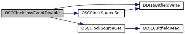
| static void | OSCClockLossEventDisable (void) |
| Disables OSC clock loss event detection. More... | |
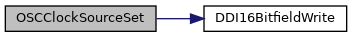
| void | OSCClockSourceSet (uint32_t ui32SrcClk, uint32_t ui32Osc) |
| Configure the oscillator input to the a source clock. More... | |
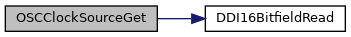
| uint32_t | OSCClockSourceGet (uint32_t ui32SrcClk) |
| Get the source clock settings. More... | |
| static bool | OSCHfSourceReady (void) |
| Check if the HF clock source is ready to be switched. More... | |
| static void | OSCHfSourceSwitch (void) |
| Switch the high frequency clock. More... | |
| static bool | OSC_IsHPOSCEnabled (void) |
| Identifies if HPOSC is enabled. More... | |
| static bool | OSC_IsHPOSCEnabledWithHfDerivedLfClock (void) |
| Identifies if HPOSC is enabled and that SCLK_LF is derived from XOSC_HF. More... | |
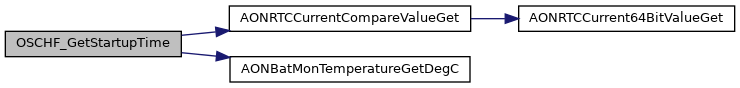
| uint32_t | OSCHF_GetStartupTime (uint32_t timeUntilWakeupInMs) |
| Returns maximum startup time (in microseconds) of XOSC_HF. More... | |
| void | OSCHF_TurnOnXosc (void) |
| Turns on XOSC_HF (but without switching to XOSC_HF). More... | |
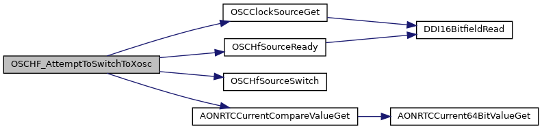
| bool | OSCHF_AttemptToSwitchToXosc (void) |
| Switch to XOSC_HF if XOSC_HF is ready. More... | |
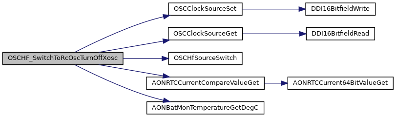
| void | OSCHF_SwitchToRcOscTurnOffXosc (void) |
| Switch to RCOSC_HF and turn off XOSC_HF. More... | |
| uint32_t | OSCHF_DebugGetCrystalAmplitude (void) |
| Get crystal amplitude (assuming crystal is running). More... | |
| uint32_t | OSCHF_DebugGetExpectedAverageCrystalAmplitude (void) |
| Get the expected average crystal amplitude. More... | |
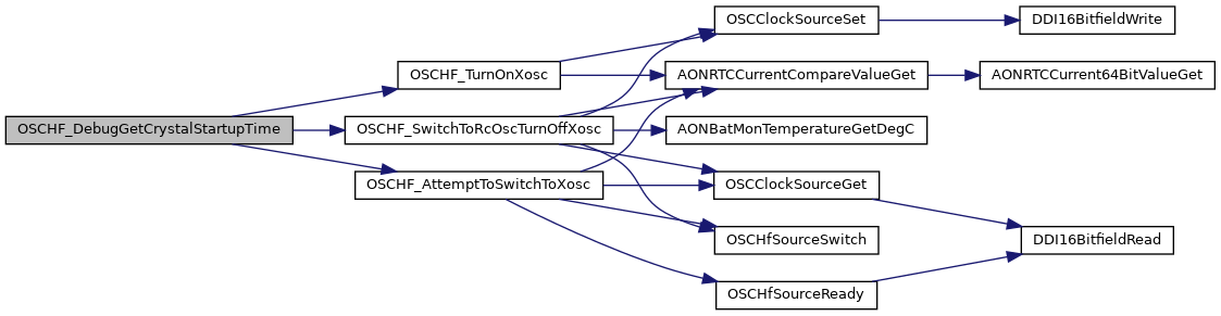
| uint32_t | OSCHF_DebugGetCrystalStartupTime (void) |
| Measure the crystal startup time. More... | |
| void | OSC_HPOSCInitializeFrequencyOffsetParameters (void) |
| HPOSC initialization function. Must always be called before using HPOSC. More... | |
| void | OSC_HPOSC_Debug_InitFreqOffsetParams (HposcDebugData_t *pDebugData) |
| Debug function to calculate the HPOSC polynomials for experimental data sets. More... | |
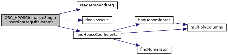
| void | OSC_HPOSCInitializeSingleInsertionFreqOffsParams (uint32_t measFieldAddress) |
| Special HPOSC initialization function for single temperature compensation. More... | |
| int32_t | OSC_HPOSCRelativeFrequencyOffsetGet (int32_t tempDegC) |
| Calculate the temperature dependent relative frequency offset of HPOSC. More... | |
| void | OSC_CapArrayAdjustWorkaround_Boot (void) |
| Special XOSC_HF workaround adjustment for CC13x2 / CC26x2 XOSC_CAPARRAY_DELTA setting in CCFG (Customer configuration) More... | |
| void | OSC_AdjustXoscHfCapArray (int32_t capArrDelta) |
| Adjust the XOSC HF cap array relative to the factory setting. More... | |
| int16_t | OSC_HPOSCRelativeFrequencyOffsetToRFCoreFormatConvert (int32_t HPOSC_RelFreqOffset) |
| Converts the relative frequency offset of HPOSC to the RF Core parameter format. More... | |
| void | OSC_HPOSCRtcCompensate (int32_t relFreqOffset) |
| Compensate the RTC increment based on the relative frequency offset of HPOSC. More... | |
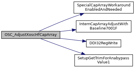
| void OSC_AdjustXoscHfCapArray | ( | int32_t | capArrDelta | ) |
Adjust the XOSC HF cap array relative to the factory setting.
The cap array factory setting (FCFG) can be converted to a number in the range 0 - 63. Both this function and the customer configuration (CCFG) setting can apply a delta to the FCFG setting. The CCFG setting is automatically applied at boot time (See ../startup_files/ccfg.c). Calling this function will discard the CCFG setting and adjust relative to the FCFG setting.
| capArrDelta | specifies number of step to adjust the cap array relative to the factory setting. |
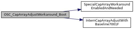
| void OSC_CapArrayAdjustWorkaround_Boot | ( | void | ) |
Special XOSC_HF workaround adjustment for CC13x2 / CC26x2 XOSC_CAPARRAY_DELTA setting in CCFG (Customer configuration)
Implements a workaround for devices with an unfortunate XOSH_HF CAPARRAY factory configuration (FCFG1 setting). The workaround is done only if both enabled and needed (enabled by setting CCFG_SIZE_AND_DIS_FLAGS_DIS_LINEAR_CAPARRAY_DELTA_WORKAROUND = 0) The factory configuration works fine on its own but does not comply with the requirements of the CCFG:XOSC_CAPARRAY_DELTA mechanism. Without this workaround, there will be a larger jump in capacitance (and frequency) between XOSC_CAPARRAY_DELTA setting 7 and 8.
Referenced by TrimAfterColdResetWakeupFromShutDown().
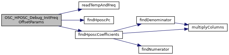
| void OSC_HPOSC_Debug_InitFreqOffsetParams | ( | HposcDebugData_t * | pDebugData | ) |
Debug function to calculate the HPOSC polynomials for experimental data sets.
| pDebugData | pointer to the input data collected in HposcDebugData_t |
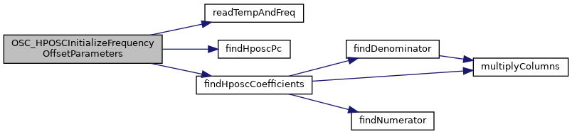
| void OSC_HPOSCInitializeFrequencyOffsetParameters | ( | void | ) |
HPOSC initialization function. Must always be called before using HPOSC.
Calculates the fitting curve parameters (polynomials) to be used by the HPOSC temperature compensation.
Referenced by OSC_IsHPOSCEnabledWithHfDerivedLfClock().
| void OSC_HPOSCInitializeSingleInsertionFreqOffsParams | ( | uint32_t | measFieldAddress | ) |
Special HPOSC initialization function for single temperature compensation.
Used when a single temperature offset measurement is available. This is espesially designed to get a better crystal performance (SW TCXO) on the SiP module but can also be usful to get better crystal performance over the entire temperature range on a standard design as well.
| int32_t OSC_HPOSCRelativeFrequencyOffsetGet | ( | int32_t | tempDegC | ) |
Calculate the temperature dependent relative frequency offset of HPOSC.
The HPOSC (High Precision Oscillator) frequency will vary slightly with chip temperature. The frequency offset from the nominal value can be predicted based on second order linear interpolation using coefficients measured in chip production and stored as factory configuration parameters.
This function calculates the relative frequency offset, defined as:
F_HPOSC = F_nom * (1 + d/(2^22))
where
By knowing the relative frequency offset it is then possible to compensate any timing related values accordingly.
| tempDegC | is the chip temperature in degrees Celsius. Use the function AONBatMonTemperatureGetDegC() to get current chip temperature. |
| int16_t OSC_HPOSCRelativeFrequencyOffsetToRFCoreFormatConvert | ( | int32_t | HPOSC_RelFreqOffset | ) |
Converts the relative frequency offset of HPOSC to the RF Core parameter format.
The HPOSC (High Precision Oscillator) clock is used by the RF Core. To compensate for a frequency offset in the frequency of the clock source, a frequency offset parameter can be provided as part of the radio configuration override setting list to enable compensation of the RF synthesizer frequency, symbol timing, and radio timer to still achieve correct frequencies.
The RF Core takes a relative frequency offset parameter defined differently compared to the relative frequency offset parameter returned from function OSC_HPOSCRelativeFrequencyOffsetGet() and thus needs to be converted:
F_nom = F_HPOSC * (1 + RfCoreRelFreqOffset/(2^22))
where
| HPOSC_RelFreqOffset | is the relative frequency offset parameter d returned from OSC_HPOSCRelativeFrequencyOffsetGet() |
| void OSC_HPOSCRtcCompensate | ( | int32_t | relFreqOffset | ) |
Compensate the RTC increment based on the relative frequency offset of HPOSC.
The HPOSC (High Precision Oscillator) frequency will vary slightly with chip temperature. This variation forces the RTC increment to be compensated if SCLK_LF is configured to be derived from the HF clock of HPOSC. This function must only be called if SCLK_LF is configured to be derived from the HF clock of HPOSC. The status of this configuration can be determined by calling the OSC_IsHPOSCEnabledWithHfDerivedLfClock() function.
This function first calculates the HPOSC frequency, defined as:
F_HPOSC = F_nom * (1 + d/(2^22))
where
F_SCLK_LF = F_HPOSC / 1536
Then the RTC increment SUBSECINC is calculated, defined as;
SUBSECINC = (2^38) / F_SCLK_LF
Finally the RTC module is updated with the calculated SUBSECINC value.| relFreqOffset | is the relative frequency offset parameter d returned from OSC_HPOSCRelativeFrequencyOffsetGet() |

|
inlinestatic |
Identifies if HPOSC is enabled.
This function checks if the device supports HPOSC and that HPOSC is selected as HF oscillator for use when the radio is active.
true : HPOSC is enabled.false : HPOSC is not enabled.
|
inlinestatic |
Identifies if HPOSC is enabled and that SCLK_LF is derived from XOSC_HF.
This function checks if the device supports HPOSC and that HPOSC is selected as HF oscillator for use when the radio is active and also that SCLK_LF is derived from XOSC_HF.
true : HPOSC is enabled and SCLK_LF is derived from XOSC_HF.false : Either HPOSC not enabled or SCLK_LF is not derived from XOSC_HF. 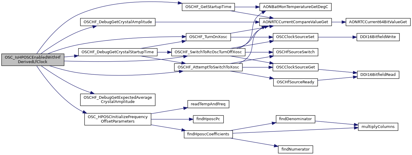
|
inlinestatic |
Disables OSC clock loss event detection.
Disabling the OSC clock loss event does also clear the clock loss event flag.
|
inlinestatic |
Enables OSC clock loss event detection.
Enables the clock loss event flag to be raised if a clock loss is detected.

| uint32_t OSCClockSourceGet | ( | uint32_t | ui32SrcClk | ) |
Get the source clock settings.
Use this function to get the oscillator source for one of the system source clocks.
| ui32SrcClk | is the source clock to check. |
Referenced by OSCClockLossEventDisable(), OSCHF_AttemptToSwitchToXosc(), OSCHF_SwitchToRcOscTurnOffXosc(), and SetupAfterColdResetWakeupFromShutDownCfg3().
| void OSCClockSourceSet | ( | uint32_t | ui32SrcClk, |
| uint32_t | ui32Osc | ||
| ) |
Configure the oscillator input to the a source clock.
Use this function to set the oscillator source for one or more of the system source clocks.
When selecting the high frequency clock source (OSC_SRC_CLK_HF), this function will not do the actual switch. Enabling the high frequency XTAL can take several hundred micro seconds, so the actual switch is done in a separate function, OSCHfSourceSwitch(), leaving System CPU free to perform other tasks as the XTAL starts up.
| ui32SrcClk | is the source clocks to configure. |
| ui32Osc | is the oscillator that drives the source clock.
|
Referenced by OSCClockLossEventDisable(), OSCHF_SwitchToRcOscTurnOffXosc(), OSCHF_TurnOnXosc(), and SetupAfterColdResetWakeupFromShutDownCfg3().
| bool OSCHF_AttemptToSwitchToXosc | ( | void | ) |
Switch to XOSC_HF if XOSC_HF is ready.
This is a non-blocking function checking if the XOSC_HF is ready and performs the switching if ready. The function is somewhat blocking in the case where switching is performed.
true : Switching to XOSC_HF has occurred.false : Switching has not occurred. Referenced by OSC_IsHPOSCEnabledWithHfDerivedLfClock(), and OSCHF_DebugGetCrystalStartupTime().
| uint32_t OSCHF_DebugGetCrystalAmplitude | ( | void | ) |
Get crystal amplitude (assuming crystal is running).
This function uses an on-chip ADC and peak detector for reading the crystal amplitude. The measurement time is set to 4 milliseconds and this function does not return before the measurement is done.
Expected value is OSCHF_DebugGetExpectedAverageCrystalAmplitude +/- 50 millivolt.
Referenced by OSC_IsHPOSCEnabledWithHfDerivedLfClock().

| uint32_t OSCHF_DebugGetCrystalStartupTime | ( | void | ) |
Measure the crystal startup time.
This function assumes that the chip is running on RCOSC_HF when called. It then switches to XOSC_HF while measuring number of LF-clock edges before XOSC_HF has started and are ready to be used. After that, the function switches back to RCOSC_HF and returns number of LF-edges found.
The length in time between the LF clock edges is approximately 15 microseconds. Or more exactly: LF_clock_edges / ( 32768 * 2 ) seconds.
Please note that the startup time, in addition to the crystal itself also can vary depending on the time since the crystal was stopped and the frequency of the RCOSC_HF oscillator. Calling this function intensively will show a shorter startup time than in typical use cases. When running with TI-RTOS there is a background task (optional but default on) adjusting RCOSC_HF to be as equal as possible to the crystal frequency, giving the shortest possible startup time.
Referenced by OSC_IsHPOSCEnabledWithHfDerivedLfClock().
| uint32_t OSCHF_DebugGetExpectedAverageCrystalAmplitude | ( | void | ) |
Get the expected average crystal amplitude.
This function read the configured high and low thresholds and returns the mean value converted to millivolt.
Referenced by OSC_IsHPOSCEnabledWithHfDerivedLfClock().
| uint32_t OSCHF_GetStartupTime | ( | uint32_t | timeUntilWakeupInMs | ) |
Returns maximum startup time (in microseconds) of XOSC_HF.
The startup time depends on several factors. This function calculates the maximum startup time based on statistical information.
| timeUntilWakeupInMs | indicates how long time (milliseconds) to the startup will occur. |
Referenced by OSC_IsHPOSCEnabledWithHfDerivedLfClock().
| void OSCHF_SwitchToRcOscTurnOffXosc | ( | void | ) |
Switch to RCOSC_HF and turn off XOSC_HF.
This operation takes approximately 50 microseconds (can be shorter if RCOSC_HF already was running).
Referenced by OSC_IsHPOSCEnabledWithHfDerivedLfClock(), and OSCHF_DebugGetCrystalStartupTime().
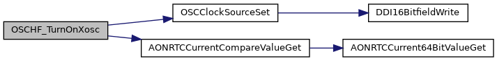
| void OSCHF_TurnOnXosc | ( | void | ) |
Turns on XOSC_HF (but without switching to XOSC_HF).
This function simply indicates the need for XOSC_HF to the hardware which initiates the XOSC_HF startup.
Referenced by OSC_IsHPOSCEnabledWithHfDerivedLfClock(), and OSCHF_DebugGetCrystalStartupTime().
|
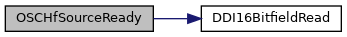
inlinestatic |
Check if the HF clock source is ready to be switched.
If a request to switch the HF clock source has been made, this function can be used to check if the clock source is ready to be switched.
Once the HF clock source is ready the switch can be performed by calling the OSCHfSourceSwitch()
true : HF clock source is ready.false : HF clock source is not ready. Referenced by OSCHF_AttemptToSwitchToXosc().
|
inlinestatic |
Switch the high frequency clock.
When switching the HF clock source the clock period might be prolonged leaving the clock 'stuck-at' high or low for a few cycles. To ensure that this does not coincide with a read access to the Flash, potentially freezing the device, the HF clock source switch must be executed from ROM.
Referenced by OSCHF_AttemptToSwitchToXosc(), and OSCHF_SwitchToRcOscTurnOffXosc().
|
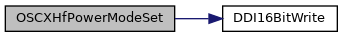
inlinestatic |
Set Power Mode for High Frequency XTAL Oscillator.
| ui32Mode | is the power mode for the HF XTAL. |
| #define HIGH_POWER_XOSC 0 |
Referenced by OSCXHfPowerModeSet().
| #define LOW_POWER_XOSC 1 |
Referenced by OSCXHfPowerModeSet().
| #define OSC_RCOSC_HF 0x00000000 |
Referenced by OSCClockSourceSet(), and OSCHF_SwitchToRcOscTurnOffXosc().
| #define OSC_RCOSC_LF 0x00000002 |
Referenced by OSCClockSourceSet(), and SetupAfterColdResetWakeupFromShutDownCfg3().
| #define OSC_SRC_CLK_HF 0x00000001 |
| #define OSC_SRC_CLK_LF 0x00000004 |
Referenced by OSCClockSourceGet(), OSCClockSourceSet(), and SetupAfterColdResetWakeupFromShutDownCfg3().
| #define OSC_XOSC_HF 0x00000001 |
| #define OSC_XOSC_LF 0x00000003 |
Referenced by OSCClockSourceSet(), and SetupAfterColdResetWakeupFromShutDownCfg3().
| #define SCLK_HF_RCOSC_HF 0 |
| #define SCLK_HF_XOSC_HF 1 |
| #define SCLK_LF_FROM_RCOSC_HF 0 |
| #define SCLK_LF_FROM_RCOSC_LF 2 |
| #define SCLK_LF_FROM_XOSC_HF 1 |
| #define SCLK_LF_FROM_XOSC_LF 3 |