7.2. MSP430F5529 LED Dashboard (Serial) (v2 Component Library)
Visualize your LaunchPad LED on a GUI Composer Dashboard
7.2.1. Introduction
In this tutorial, we will show you how to send your MSP430F5529 or MSP430G2553 LaunchPad LED states over UART port and build a dashboard using GUI Composer.
7.2.2. Preparation
Here’s what you need to run this tutorial:
A MSP430F5529 or MSP430G2553 LaunchPad
The latest version of the Chrome web browser
A myTI account for accessing CCS CLoud and GUI Composer
Please note that MSP430G2553 LaunchPad is only supported on Windows and there are additional steps to build and flash the program.
7.2.3. Get your LaunchPad Programmed
Program your LaunchPad to send its LED state over UART port.
Plug your LaunchPad into the computer with the included USB cable.
ccs_code
Import the project to the CCS CLoud by clicking
 above. A new window will launch and you may need
to provide your myTI login credentials.
above. A new window will launch and you may need
to provide your myTI login credentials.
In CCS Cloud, flash the project to your LaunchPad by pressing the
 run button. You may need to install TI Cloud
Agent,
which adds a browser extension and local driver files that let Chrome
communicate with the LaunchPad.
run button. You may need to install TI Cloud
Agent,
which adds a browser extension and local driver files that let Chrome
communicate with the LaunchPad.Now check to see if your LaunchPad is sending anything to the serial port. In CCS Cloud,at the top right menu, click Target → Connect COM Port. Select the COM port and set the baud rate to 9600 and click Connect. You should see that the LED states are being sent in the Serial Monitor.
CCS Cloud will automatically try to determine correct COM port.
However, it may not be able to correctly do so in all cases, e.g. when there are multiple LaunchPads connected. Please ensure that the correct COM port for your device is selected.
Once you confirm that the target is sending out data to the serial port, click Target → Disconnect COM Port. This will free the port for GUI Composer to connect to your Launchpad.
Download the generated executable within CCS Cloud for use later in GUI Composer. You will need this file during project creation. The
.outfile is located insideDebugfolder. Simply right click on the file ending in.outand choose Download File.
7.2.4. Build your own dashboard on the cloud
Go to GUI Composer. You may need to login using your myTI credentials.
At the GUI Composer landing page, click CREATE A NEW PROJECT to open the New Project Wizard.
At the New Project Wizard, set your project template as
Dashboard. Click onAutofilland click Next.
Fig. 7.7 newprojfirstpage
On Target Programming page, type in your device name. Select your device from drop down box. The device selection list may be filtered to limit choice by typing first few letters of the device name. The connection list should automatically adjust to the right debugger to use.
Upload your .out file to program the device with the executable.
This step will ensure that correct firmware is programmed. Then click
Next.
On Target communication setting page, click on
 and select
USB-UART. From the Available Models dropdown, select
Streaming from the drop down and press Add. Then ensure that
protocol selection is configured to json. A new model is created, and
the model id will be
and select
USB-UART. From the Available Models dropdown, select
Streaming from the drop down and press Add. Then ensure that
protocol selection is configured to json. A new model is created, and
the model id will be ti_model_programby default.
Fig. 7.8 Serial_TargetComm_Uart_Json
Click connect to test the connection.
Click the Connect button and switch to the Console tab in the Target Communication page
You can click Console tab to verify there are no errors.
When the connection is established, the connect button will be changed to

When device data is received, the device status icon
 will change to
  .
.
Click OK to save the configuration and close New Project Wizard dialog.
Fig. 7.9 SerialConnectTest
Start to add your first widget by clicking on the
 button
on the left column to open the Component Palette.
button
on the left column to open the Component Palette.
Under Instrument Tiles, select LED
Drag and drop the text onto the grid to create a LED that will display status of physical LED on the LaunchPad.
Under Instrument Tiles, select Toggle Switch
Drag and drop the text onto the grid to create a Toggle Switch that will control whether LED is blinking or not.
This is what the dashboard looks like after the tile is added.
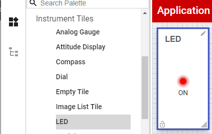
Fig. 7.10 serial_NewTileProperty
After the LED tile is created, you will find a graphical LED tile and a toggle switch in the center and the tile property editor
 on the right column.
In the BlinkJsonUart project, the LaunchPad is programmed to blink the LED and send the LED status over the serial port encoded in JSON format. The status object has a member called LED.
In the tile property editor, you can bind variable to a property of the tile widget as follows:
Select the Toggle Switch widget in the designer and click
 on
the the value property to initiate the binding.
on
the the value property to initiate the binding.By default,
ti_model_programis selected; this refers to the data connection you created.
Enter LED in text box and click CLOSE.
The animation below illustrates the steps to bind the member of JSON object.
Fig. 7.11 serial-setTileBinding
Click the preview button
 to preview your dashboard. A new
browser window or tab will be opened to display the dashboard.
to preview your dashboard. A new
browser window or tab will be opened to display the dashboard.
Why is the dashboard not displayed?
The web browser security setting may disallow pop-up from a website. You need to add our GUI Composer Cloud website to the list of exceptions to allow the dashboard to pop up.
You have previewed your dashboard application! You should bookmark the URL of your preview window so you can open the dashboard on another PC or mobile devices by visiting this URL; you may need to provide your myTi login credentials.
This is what the dashboard preview looks like:
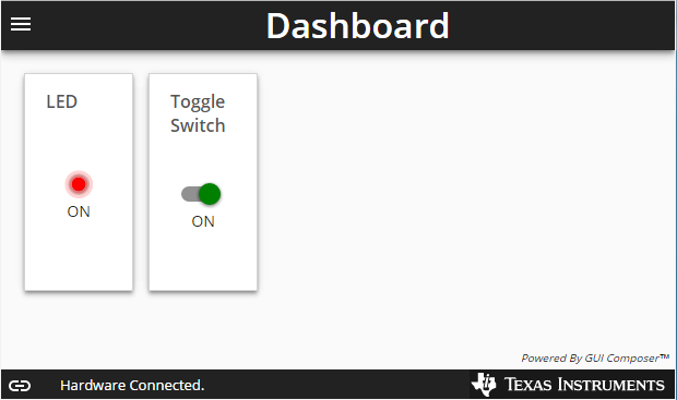
Fig. 7.12 monitor-preview
7.2.4.1. Publish your app
You may now also publish your application to Gallery, a repository of GUI Composer applications. Click on File → Publish to Gallery to publish your application. You will still need to provide your log in credentials, however further changes in GUI Composer Designer will not be reflected in Gallery until you re-publish again.
Publishing will activate new tab and show your application in that tab. To go back to GUI Composer Designer, please select GUI Composer browser tab.
You may also download your application to desktop and combine it with GUI Composer Runtime to run your application as a desktop app. See the Deploy section in the User Guide for more information.
Congratulations! You have completed your tutorial.